
Abstract
With the growing use of mobile robots in home applications, e-commerce warehouses, and so on it is necessary to pay attention to their object carrying capability for transferring objects from one location to another. The shape of the object to be carried may vary based on the type of surface (planar/nonplanar). For an instant, the surface of a cylinder is nonplanar. Thus, when the mobile robot tries to track a desired trajectory with a cylinder kept on its top surface, the cylinder may fall on the ground due to its uncontrolled rolling motion. Thus, in order to address the problem, this article presents a novel approach for a Mecanum wheeled mobile robot with a cylinder, for simultaneous balancing and tracking task. In this approach, first, the mathematical modeling of Mecanum wheeled mobile robot with the cylinder on its top surface is done using Newton–Euler approach. Then, to prevent the cylinder from falling, while Mecanum wheeled mobile robot is following a desired path, switching between two robust controllers is utilized to obtain a feasible reference trajectory. The robust control laws are derived using second-order sliding mode controller. In order to ensure the stability of the controller, Lyapunov stability proof of the established theorem has been provided. Later, the Mecanum wheeled mobile robot is made to follow a generated reference trajectory using the robust controller of the mobile robot. The proposed approach is implemented in MATLAB/Simulink. The simulation results proved the efficacy of the proposed approach such that Mecanum wheeled mobile robot followed the desired path with cylinder on its top surface. Moreover, results of statistical analysis have been presented, and comparison with proportional integral derivative (PID) controller is done to prove the superiority of the proposed approach.
Introduction
With the advancement of services provided by the robots, mankind has benefitted a lot. One of the well-known systems is the wheeled mobile robots which have been extremely used for various applications. Omnidirectional mobile robot is one of the examples of wheeled mobile robots. Although there are many types of omnidirectional mobile robots, 1 Mecanum wheeled mobile robot (MWMR) is one of them. The MWMR used in the current work is characterized by four Mecanum wheels, configured with a chassis and a plane top surface, with each wheel coupled to a DC motor. Kinematic and dynamic modeling and trajectory tracking with MWMR have been performed by various researchers in the past. 2 –5 Capability to perform translation and rotational motion separately and synchronously are the main aspects of MWMR. This unique specification makes it really efficient for use in different areas, such as hospitals, warehouses, power plants, military applications, and so on.
Wheeled mobile robots are often used for object carrying applications. However, due to the inertial force and torque induction, the object may be subjected to slipping motion depending upon the magnitude of friction forces. Yazaki et al. 6 addressed this problem and proposed a control law in order to carry the object while traveling. However, the shape of the object consisted of a single or multiple plane surfaces which provides enough friction force to avoid the object from falling on the ground. Hence, an object with the plane surface has less possibility to fall on the ground, while the mobile robot is tracking a reference trajectory. However, with recent development in robotic applications, it is a need to introduce an algorithm to carry objects with nonplanar surfaces. For example, nowadays in many developed countries, mobile robots are used to carry the objects from one place to another in houses or office working areas. Moreover, mobile robots are also used to carry unmanned aerial vehicle (UAV) to the flying zone where the shape of UAV’s is not restricted to only plane surfaces. Today, UAVs are of various shapes such as circular, cylindrical, egg shaped, and so on, which does not have any plane surface. One example of egg-shaped UAV can be Poweregg drone introduced by PowerVision. Thus, it is important that the object carrying capability of a mobile robot should be extended to objects with a curved surface. Since many years, various objects are carried in industries by mobile robots using fixtures leading to reduction of production efficiency. Thus, this research addresses the above issue limited to mobile robot carrying a cylindrical object.
As the cylinder moves on the top surface of MWMR, friction force will act between surfaces of both the bodies. The movement of the cylinder is because of rolling or sliding motion. Depending upon the type of motion and type of surface (dry/wet), it is important to select a suitable friction model. There are different types of friction models depending upon the type of surface contact, applications, and running conditions. The most frequently used model is the Coulomb friction model which is generally used for dry contacts. 7,8 Apart from this, Stribeck friction model is used when the contacts are lubricated. 7 Kudra and Awrejcewicz 9 developed an approximate model of dry friction force and rolling resistance force. Borisov et al. 10 experimentally presented the results of the dynamic behavior of the cylinder sliding on a rough horizontal surface under the action of dry friction. Although there are various friction models available in the literature, in the current article, classical Coulomb friction model has been used to derive the equation of motion. The reason for such model selection is the assumption that the cylinder performs pure rolling motion on a smooth dry horizontal surface.
The objective of the current article is to balance the cylinder on MWMR, while the latter is tracking a reference path with former having no actuation. In other words, it can also be said that MWMR has to avoid fall of the cylinder, while MWMR is following a desired path. Having said that the cylinder does not have any actuation, it means that its movement is dependent upon the motion of MWMR. If MWMR and cylinder are considered as a system, then the positions and orientations have to be controlled by only four motors, attached to each of the four Mecanum wheels. Thus, it is a class of underactuated system where there are total six parameters (two positions and one orientation for each of the mobile robot and cylindrical object) which have to be controlled. In the past, various control strategies have been developed for the control of underactuated systems. 11 –13 One of the most common underactuated systems is the wheeled inverted pendulum. Yue et al. 14 performed simultaneous balancing and trajectory tracking task for the same using a composite control. Recently, Roose et al. 15 proposed a fuzzy logic control strategy for an inverted pendulum cart system. Yet, in all the works, the object to be balanced was actuated through motors whereas in the current work, the cylinder to be balanced has got no actuation. Moreover, the objective becomes challenging because it is difficult to define a control law which can minimize the tracking error of each of the six variables. This can be explained in detail by an example. Let us assume a MWMR with a cylindrical object on its top surface as shown in Figure 1(a). Now, the aim of MWMR is to follow a straight trajectory by avoiding the fall of the cylinder from its top surface. In other words, it can be said that both MWMR and cylinder have to follow the same path. Now, if higher control gain parameters for a control law are selected for the MWMR system, the controller will give priority to mobile robots desired trajectory, and as per dynamics, the cylinder will move in the opposite motion due to pure rolling (Figure 1(b)). Similarly, higher control gain parameters of cylinder system will move the cylinder in the forward direction, which is only possible if MWMR moves in the backward direction (Figure 1(c)). Yet, one can think to find optimal values for the control gain parameters. But, the task becomes more difficult as selecting a common objective function is a challenging job. Hence, to address the simultaneous trajectory tracking and balancing problem, a control architecture has been developed where switching between two robust controllers is done to get feasible trajectories for both MWMR and cylinder. In the current article, the feasible trajectory is the possible trajectory following which the mobile robot cylinder system can perform simultaneous tracking and balancing. This trajectory is based on certain conditions which are explained in detail in “Control algorithm” section.

MWMR with cylinder: (a) initial position, (b) high control gain parameters with respect to mobile robot, and (c) high control gain parameters with respect to cylinder. MWMR: Mecanum wheeled mobile robot.
In order to complete the objective, it is beneficial that the controller has good tracking performance along with quick response and robustness. Thus, sliding mode control concept has been utilized to derive the control law. 16 –18 It is a robust control law in which the system trajectories are moved on a sliding surface. It is widely used for controlling robotic systems. 19 –21 However, the tracking is performed at the cost of poor control performance as the controller is prone to chattering effects. Thus, second-order sliding mode controller (SSMC) has been used instead of first-order sliding mode controller to avoid chattering effects in which first order of the sliding surface is bought to zero. 22,23 Recently, Alakshendra et al. 24 proved the superiority of SSMC with a different control law over conventional sliding mode controller while tracking a desired nonlinear path. Also, SSMC has better tracking performance compared to first-order sliding mode controller and has a quick response which is required for the current objective. Hence, motivated by the advantages of the SSMC, this article utilizes the concept to derive two robust control laws.
The major contributions of the current work are as follows: Derivation of an equation of motion for an MWMR with a cylinder. Derivation of a novel control law.
Finally, a control architecture utilizing switching between two robust controllers has been designed in order to carry on simultaneous tracking and balancing.
The article is structured in the following manner: In section “Equation of motion,” equation of motion of the complete system is provided. In section “Controller design,” the control system has been designed. Control architecture is briefly described in section “Control algorithm.” The simulation results are presented in section “Simulation.” Finally, section “Conclusion” draws the conclusions of the present study.
Equation of motion
This section presents a generalized equation of motion when a cylindrical object is kept over MWMR.
Notations: Figure 2 shows different frames used for the analysis. We introduce a fixed coordinate frame {1} or
Im: moment of inertia of the mobile robot about Zm-axis (perpendicular to the plane of paper) passing through its center of gravity;
Ic: moment of inertia of the cylinder about Zc-axis (perpendicular to the plane of paper) passing through its center of gravity;
Icx: moment of inertia of the cylinder about Xc-axis passing through its center of gravity;
μ: friction coefficient between the cylinder and the top plane surface of the mobile robot;
βmx and βmy: viscous friction coefficient along Xm and Ym, respectively;
βcx and βcy: viscous friction coefficient along Xc and Yc, respectively;
βmz and βcz: viscous friction coefficient about Zm and Zc direction, respectively;
R: wheel radius;
α and β: motor characteristics coefficients; and
g: acceleration due to gravity.

Schematic of MWMR with cylinder. MWMR: Mecanum wheeled mobile robot.

Free body diagram.
In frame {1}, the equation of linear momentum balance as per Newton’s second law is written as

Using


Differentiating equation (2) with time yields

Since,

Multiplying, equation (5) by

Since


In equations (7) and (8), Fxc and Fyc are expressed as


where

where


where
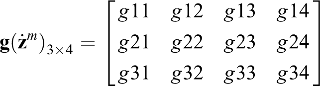
Further, MWMR equation of motion is given as 4

In order to derive the equation of motion in an input affine form, equations relating the vectors in {1} and {2}, and {1} and {3} are required which are given as


Finally, equations (15) –(19) are utilized to simplify equations (7), (8), and (10) and equations (12)–(14) in an input affine form as

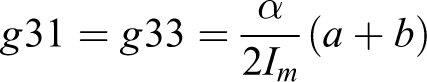
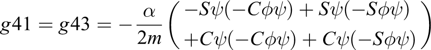
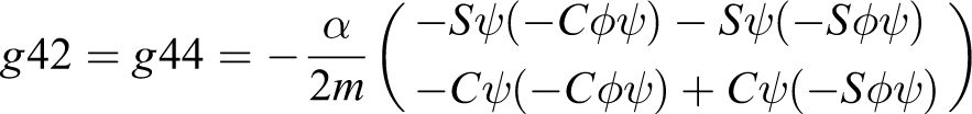
where
To analyze the motion of cylinder, while MWMR is moving, equation of motion (20) has been solved for a given input voltage. Figure 4 shows the movement of cylinder while MWMR moves along negative Xo direction by keeping φ = 0. It can be seen that up to 0.8 m the cylinder moves along with MWMR and does not fall on the ground because of the frictional force between cylinder and MWMR surface. However, when the MWMR moves along the positive Yo direction, the rolling motion of the cylinder tends to fall on the ground (Figure 5). Finally, Figure 6 shows the motion of cylinder while MWMR moves along a circular path.

MWMR straight path trajectory along the Xo direction ( MWMR,  MWMR trajectory,
  cylinder,
  cylinder trajectory). MWMR: Mecanum wheeled mobile robot.
MWMR straight path trajectory along the Yo direction ( MWMR, MWMR trajectory, cylinder, cylinder trajectory). MWMR: Mecanum wheeled mobile robot.
MWMR circular path trajectory ( MWMR, MWMR trajectory, cylinder, cylinder trajectory). MWMR: Mecanum wheeled mobile robot.
Remark 1
It is evident from Figures 5 and 6 that when MWMR has to track a circular or straight path along the Yo direction, the cylinder will fall on the ground due its rolling motions. In comparison to this, when MWMR tracks a straight path with φ = 0 along Xo (Figure 4), both cylinder and MWMR can move together up to a certain distance until a threshold value of friction force is reached.
Remark 2
As the objective of the controller is to balance the cylinder while MWMR is following a desired trajectory, the control law cannot be derived using equation (20) to achieve the same, since the desired position of the cylinder is dependent upon the motion of MWMR. For example, if MWMR tracks a straight path (along the Yo direction), the cylinder will have a tendency to move backward which will lead to fall of the cylinder. Moreover, if the cylinder tries to track the same straight path, the mobile robot will deviate from its desired path. Thus, under both the conditions, the controller will lead to an unstable system with undamped oscillations. Thus, the equation of motion given by equation (20) is divided into two sets of equations (one for the mobile robot and the other for the cylinder) to derive separate control laws for each. The equations are as follows


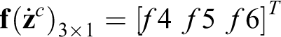
where
Let


and

where


Finally


Controller design
In this section, procedure for derivation of two control laws has been proposed. The aim of designing the controller is to prevent the cylinder from falling on the ground, as MWMR follows a desired trajectory. In order to complete the task, two separate robust control laws have been derived using second-order sliding mode approach. Initially, the steps involved in the derivation of robust control law for MWMR trajectory tracking has been explained, and latter, the control law for cylinder trajectory tracking has been provided.
SSMC for MWMR
Let,

The sliding surface is selected as

where

Then, second derivative of

According to SSMC, the tracking error converges to zero, if
In order to address the uncertainties associated with the model and environment, switching control law is taken as

where ρ is a small positive constant,


and

However, the controller fails as

with

Now, using expression of


Theorem 1
The tracking error of the dynamic system defined by equation (23) converges to zero asymptotically if the control law is defined by equation (29).
Proof
Consider a Lyapunov function as

which can be further expanded as

Substituting for

Since, for any z,
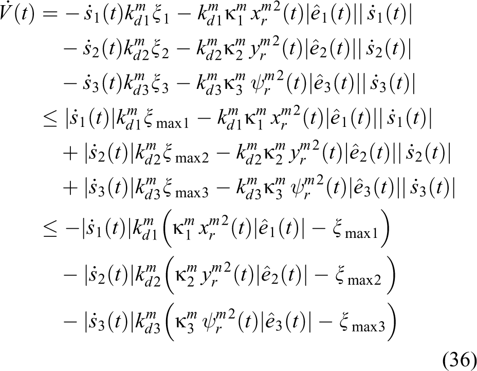
Thus, if
SSMC for cylinder
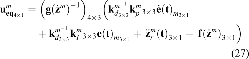
In order to track cylinder trajectory, proposed control law is derived using the same procedure as of control law for MWMR. Thus, the robust control law

where all the variables correspond to the same meaning as that of MWMR, with a difference that these are defined for a cylinder.
Control algorithm
This section describes the procedure of the controller implementation in order to complete the objective. It is evident from Remark 1 that cylinder will fall in a short period of time on the ground if MWMR tracks a straight trajectory along the Yo direction or if it tracks any nonlinear trajectory. Thus, this algorithm provides a solution through which MWMR can successfully track a straight path trajectory while avoiding the fall of cylinder on the ground. Figure 7 shows the control algorithm block diagram for performing simultaneous tracking and balancing task. Loop 1 corresponds to a basic control system block diagram. However, the controller switches between SSMC of MWMR and SSMC of cylinder. In order to perform the switching operation, an upper limit has been set for xm − xc and ym − yc. For

Block diagram of control architecture.
Next, trajectories are generated by combining the feasible trajectories for different time intervals. Finally, these trajectories are the new desired trajectories for the mobile robot and cylinder. Thus, using SSMC for MWMR, the mobile robot can track the generated trajectory while carrying the cylinder on its top surface.
However, the limitation of this algorithm is its inability to track a curved/nonlinear path. Yet, if a curved path is considered as segments of perpendicular lines as shown in Figure 8, MWMR can perform the tracking task without falling cylinder on the ground. Moreover, the tracking should be performed by maintaining zero heading angle of MWMR. In order to justify this statement, simulation has been performed in next section for one segment which is a combination of path along Yo and Xo directions.

Approximation of a curve path.
Remark 3
The switching condition should be selected within a certain range, depending upon the dimensions of the cylinder and mobile robots top surface. Higher upper limit of xm − xc and ym − yc can lead to high-frequency oscillations, which will increase the overshoot and settling time.
Simulation results
In this section, simulation results are presented for a straight path which is a combination of path along Yo and Xo directions. Latter, comparison of the results is done with proportional integral derivative (PID) controller. The mechanical parameters of the mobile robot are taken as m = 6 kg, R = 0.05 m, Im
= 0.0945 kg·m2, 2a = 0.22 m, 2b = 0.36 m, α = 0.087 N/V, β = 11.4 kg/s, and μ = 0.1. Similarly, mechanical properties of the cylindrical body is taken as mc
= 0.05 kg,
In the first stage of simulation, results are presented for the output of loop 1, that is, feasible trajectory. The desired trajectories (input of loop 1) for MWMR and cylinder are taken as
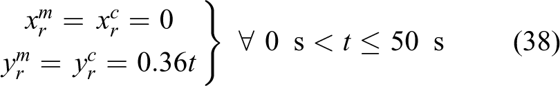
Further, to obtain feasible trajectories for MWMR and cylinder, positive constants, switching gains, and control gains are taken as
Simulations are carried out using MATLAB/Simulink. Figure 9 shows the Simulink block model for the generation of trajectories. In order to test the system, a simulation environment has been also built using Simscape. The output of the system dynamics block in Figure 9 is the feasible trajectory (Figure 10) for MWMR and cylinder. It can be seen in Figure 10, till 37.41 s

Simulink model for trajectory generation.

Feasible trajectory (time history).
Next, this feasible trajectory is combined at different time intervals to generate a trajectory so that both MWMR and cylinder can cover more distance. Further, as said in the last section, the aim of MWMR is to track a segment of perpendicular line, the generated trajectory is further combined with a trajectory after 728 s so that MWMR and cylinder can move along the Xo direction which is shown in Figures 11 and 12. Finally, it can be said that to track a segment of perpendicular line, desired trajectory for MWMR and cylinder is shown in Figures 11 and 12. It should be noted that to move along the positive Xo direction, feasible trajectory has not been built as it is evident from Remark 1 that MWMR and cylinder can move safely up to 0.8 m.

Generated/desired trajectory along the Yo direction (time history).

Desired trajectory along the Xo direction (time history).
Having obtained the desired trajectory, now it is just a problem of trajectory tracking control. It means that the higher the efficacy of tracking the trajectory by MWMR, lesser will be the chance of cylinder to fall on the ground. Thus, to track such a complicated trajectory the controller should have high tracking performance with quick response toward sudden changes in the trajectory. Thus, this is the reason why SSMC is selected over other conventional controllers.
The obtained trajectories using SSMC are shown in Figure 13 where red rectangle represents cylinder and blue represents MWMR. It shows the path tracked by the complete system in 788 s. As per Figure 13, it is proved that the cylinder stays on the mobile robot at the end of the simulation run. The time history plot of position of MWMR is shown in Figures 14 and 15. It can be seen that the mobile robot is able to track the desired trajectory with slightly less efficacy at the switching zone. Switching zone is the region in the plot when MWMR performs backward and forward motion. However, the MWMR never deviates from its desired trajectory to a larger extent. Similarly, time history plot of cylindrical object can be seen in Figures 16 and 17 which proves the balancing capability of the control architecture. In comparison to SSMC, PID (simulated only for 728 s) is unable to fulfill the goals of a controller (Figure 18) as MWMR moves forward, dropping the cylinder on the ground which is evident from Figure 19 at 270 s. Finally, Figure 20 shows the increase in cylinder tracking error with PID controller compared to stable tracking error with use of proposed controller. The comparison of final positions of the MWMR and cylinder can be seen in Table 1. It is evident that with SSMC, the mobile robot carries the cylinder all along its straight path, whereas PID is unable to complete the task. The reason for failure of the PID controller can be related to its inefficacy to track the fast reference trajectory in the switching zone. Moreover, the difference between the positions of the mobile robot and cylinder (0.03 m for SSMC and 0.5554 m for PID) also proves the inefficacy of a PID controller to perform simultaneous tracking and balancing.

Trajectory of MWMR and cylinder with SSMC. MWMR: Mecanum wheeled mobile robot; SSMC: second-order sliding mode controller.
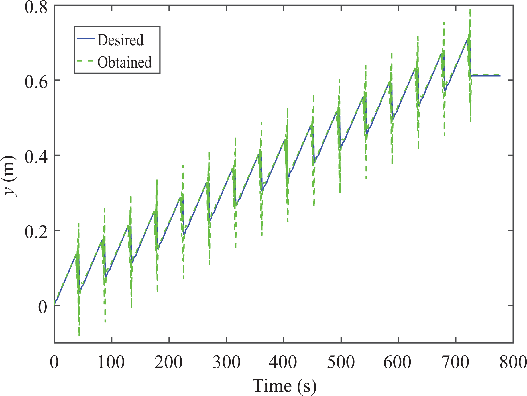
Comparison of obtained MWMR trajectory with SSMC with desired trajectory (time history). MWMR: Mecanum wheeled mobile robot; SSMC: second-order sliding mode controller.

Zoom in view of Figure 14.

Comparison of obtained cylinder trajectory with SSMC with desired trajectory (time history). SSMC: second-order sliding mode controller.

Zoom in view of Figure 16.

Trajectories of mobile robot and cylinder with PID: (a) t = 0 s, (b) t > 0 s, (c) t > 0 s, and (d) t = 728 s ( mobile robot trajectory and cylinder trajectory).

Comparison of obtained cylinder trajectory with desired trajectory with PID (time history).

Comparison of cylinder trajectory error.
Comparison of final positions.

SSMC: second-order sliding mode controller.
In order to point out the accuracy obtained during tracking of MWMR and cylinder trajectories, Table 2 has been constructed. It shows the statistical data related to the absolute tracking error obtained during the simulations. It can be noticed that the mean and standard deviation of the mobile robot tracking error are close to zero and both the controllers are able to track the desired straight path. However, there is a big difference in the mean and standard deviation values of both the controllers for the cylinder tracking error. It can be seen that these statistical values are high for a PID controller compared to SSMC. This is because of the reason that the mobile robot leaves the cylinder at 270 s to follow its own straight path trajectory. Thus, the error statistical analysis proves that if the proposed control architecture is utilized for completing the mentioned goals, the mobile robot can perform simultaneous tracking and balancing along a straight path. Finally, the output of the Simscape model in Matlab Mechanics Explorer is shown in Figure 21 and simulation video (Online Supplementary) is provided in the multimedia file.
Statistical error data comparison

SSMC: second-order sliding mode controller.
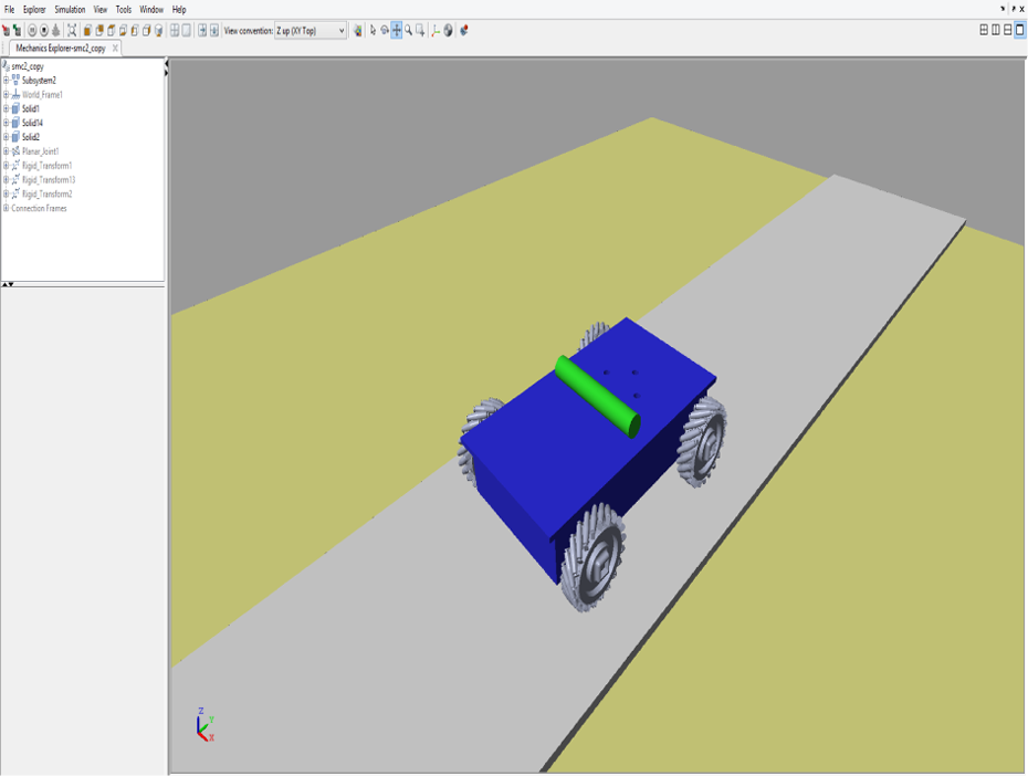
Screenshot of Matlab Mechanics Explorer.
Conclusion
In this article, a new underactuated system has been proposed where a mobile robot is capable of balancing a cylinder from one location to another while tracking a desired trajectory. The Newton–Euler method is used to derive the equation of motion in the presence of viscous friction and Coulomb friction between the mobile robot top surface and cylinder. The dynamic equation results suggested it is impossible to carry the cylinder even for a straight path as cylinder’s rolling motion forces it to fall on the ground. Thus, a novel control architecture is used to solve the issue which uses switching between two robust controllers to obtain feasible trajectories for the mobile robot and cylinder. Moreover, SSMC is used to track cylinder and MWMR trajectories. Further, SSMC control law stability is proved as per Lyapunov stability theory. Later, the obtained feasible trajectory has been used to construct the generated trajectories following which MWMR can track a straight path while balancing the cylinder on its top surface. The simulation results proved that the mobile robot can successfully track a straight path while balancing the cylinder. Moreover, comparison of the proposed technique with the PID controller showed that it is unable to balance the cylinder because of its slow response during switching zone. Finally, statistical error data analysis concluded the results in favor of the proposed method by giving lower values for mean and standard deviation.
Footnotes
Declaration of conflicting interests
The author(s) declared no potential conflicts of interest with respect to the research, authorship, and/or publication of this article.
Funding
The author(s) received no financial support for the research, authorship, and/or publication of this article.
Supplemental material
Supplementary material for this article is available online.
References
Supplementary Material
Please find the following supplemental material available below.
For Open Access articles published under a Creative Commons License, all supplemental material carries the same license as the article it is associated with.
For non-Open Access articles published, all supplemental material carries a non-exclusive license, and permission requests for re-use of supplemental material or any part of supplemental material shall be sent directly to the copyright owner as specified in the copyright notice associated with the article.