
Abstract
Collaborative dynamics modeling of flexible multibody and rigid multibody for an electromagnetic direct-drive vehicle robot driver is proposed in the article. First, spatial dynamic equations of the direct-drive vehicle robot driver are obtained based on multibody system dynamics. Then, the shift manipulator dynamics model and the mechanical leg dynamics model are established on the basis of the multibody dynamics equations. After establishing a rigid multibody dynamics model and conducting finite element mesh and finite element discrete processing, a flexible multibody dynamics modeling of the electromagnetic direct-drive vehicle robot driver is established. The comparison of the simulation results between rigid and flexible multibody is performed. Simulation and experimental results show the effectiveness of the presented model of the electromagnetic direct-drive vehicle robot driver.
Introduction
Vehicle robot driver is an intelligent industrial robot which can be equipped in a vehicle cab without any modification. It can be used to conduct autonomous driving replace of a human driver. Because the vehicle is not required to be modified, and the vehicle robot driver can be directly installed in the different vehicle cabs, its related technologies can be applied to emission durability test, vehicle performance test, vehicle noise test, high and low temperature environment test, vehicle road test, vehicle bench test, and other fields. 1 –4
The drive way of the vehicle robot driver includes the hydraulic drive, the pneumatic drive, and the servo electric drive. 2 The hydraulic drive is steady, but it needs an oil cylinder. 5 It is not easy for the pneumatic drive to accurate positioning and real-time performance. 3 As a driving device of the vehicle robot driver, the servo electric drive needs a mechanism of rotary motion into linear motion. 4,6 Electromagnetic linear motor can solve the shortcomings of three other drive styles. It can improve the transmission efficiency and transmission accuracy and make the transmission mechanism simple. 7 –9 Many scholars design the direct-drive robot actuator and control algorithms. 10 –13 We adopt the electromagnetic linear motor as the drive device of the direct-drive vehicle robot driver in this article.
Flexible multibody system is composed of rigid body and flexible body. 14 –17 Previous multibody system dynamics mainly involve in multi-rigid body. Chen and Zhang conducted a kinematics simulation of an electromagnetic unmanned robot applied to automotive test based on a rigid visual prototype; however, the kinematics model is not established and the elastic deformation of shift handling rod on the shift manipulator is also not considered. 2 Zhe and Zhigang conducted a kinematics simulation analysis of automobile gear shifting manipulator; however, the shift error caused by the elastic deformation of connecting rods on shift manipulator is not considered. 18 Due to rigidity assumption, the results of accuracy will cut down, sometimes even unacceptable. For high speed and high precision mechanical systems, the rigid motion coupling and its deformation need be considered. It is necessary for the direct-drive vehicle robot driver to consider the flexibility of systems in order to improve the simulation accuracy.
It is important for the direct-drive vehicle robot driver to make dynamics simulation analysis. When the systems are regarded as rigid body, there is no deformation for motion analysis. However, under the conditions of acceleration and deceleration, after the mechanism is added to force, there will be deformation and displacement change. Automatic Dynamic Analysis of Mechanical Systems (ADAMS [version 2013]) is automatic dynamic analysis of mechanical systems software. ADAMS provides not only rigid body analysis module but also flexible body analysis module. Using the flexible body analysis module, motion simulation analysis of flexible body is achieved. HYPERMESH [version 13] is general finite element analysis software. It is with a highly effective and precise solver. Multibody dynamics modeling and simulation are conducted by combining the advantages of ADAMS and HYPERMESH. The collaborative simulation using ADAMS and HYPERMESH can reflect the dynamic motion characteristics and flexibility of the direct-drive vehicle robot driver, so that it can accurately predict the system performance.
In this article, an approach of multibody dynamics modeling and collaboration simulation for an electromagnetic direct-drive vehicle robot driver is proposed. Spatial dynamic equations of the electromagnetic direct-drive vehicle robot driver are given. Three dimensional physical model of the electromagnetic direct-drive vehicle robot driver is established by use of Computer Aided Three-dimensional Interactive Application (CATIA [version V5]). A rigid multibody dynamics model and a flexible multibody dynamics modeling of the direct-drive vehicle robot driver are built. The comparison of the rigid multibody simulation results and flexible multibody simulation results is performed. Results show the validity of the presented model.
Mechanical structure
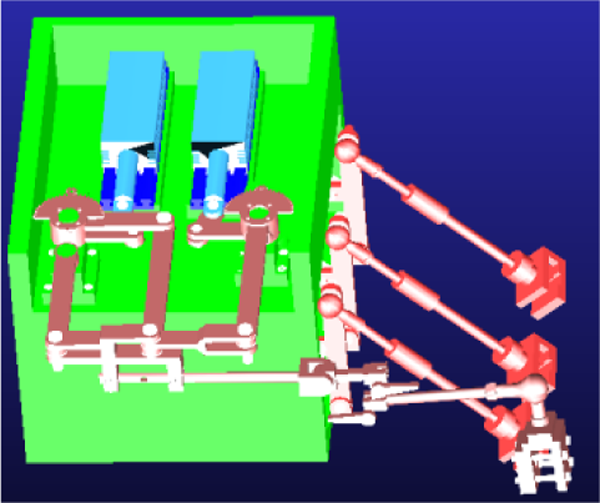
The direct-drive vehicle robot driver includes throttle mechanical leg, brake mechanical leg, clutch mechanical leg, shift manipulator, and electromagnetic linear motor as the direct-drive device. The direct-drive vehicle robot driver physical model is shown in Figure 1.
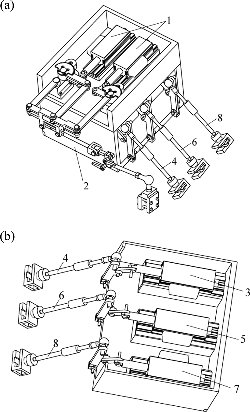
The direct-drive vehicle robot driver physical model. (a) Overall structure. (b) Mechanical leg internal structure. (1) Direct-drive linear motor of shift manipulator, (2) shift manipulator, (3) direct-drive linear motor of throttle mechanical leg, (4) throttle mechanical leg, (5) direct-drive linear motor of brake mechanical leg, (6) brake mechanical leg, (7) direct-drive linear motor of clutch mechanical leg, (8) clutch mechanical leg, and (9) mechanical base.
The shift manipulator mechanism diagram is shown in Figure 2. 2 L 11, L 12, L 21, L 22, L 31, L 32, and LPC are the length of linkage. O 1, O 2, and O 3 are the rotating base. P is the end of the shift manipulator. The mechanical leg mechanism diagram is shown in Figure 3.

Shift manipulator mechanism diagram.

Mechanical leg mechanism diagram.
Qualifications of the direct-drive vehicle robot driver are shown in Table 1. The movement error of gear selecting and gear shifting is not more than 2 mm.
Qualifications of direct-drive vehicle robot driver.

Multibody dynamics model
Multibody dynamics equations
The generalized coordinate is composed of mass center Cartesian coordinates of rigid i and Euler angles of rigid orientation.
19
Each rigid body is represented with six generalized coordinates

where x is the position vector from whole coordinate origin to the local coordinate system. A is a cosine matrix of local coordinate system origin relative to global coordinate system origin. si is the position in the local coordinate before the node i deforms. Φ i is the modal shape components of node i. h is modal amplitude vector. Assume that

Euler angle represents the direction and the motion target is

where x, y, and z are the position of local coordinate system relative to global coordinate system. ϕ, θ, and φ are the Euler angles of local coordinate system origin relative to whole coordinate system origin. hm is the modal component of m order modal amplitudes. The speed of node i is

where B is a transformation matrix of first-order derivation of Euler angles over time. The kinetic energy and the potential energy are

Flexible body motion equations can be derived by the following Lagrange equation
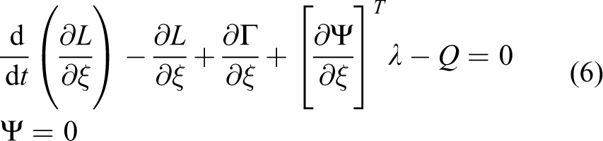
where Ψ is constraint equation, λ is Lagrange multipliers of the constraint equation, and Q is the generalized force projected to ξ. L = T − W, where T is kinetic energy and W is potential energy. Γ is energy loss function. The flexible body motion differential equation is
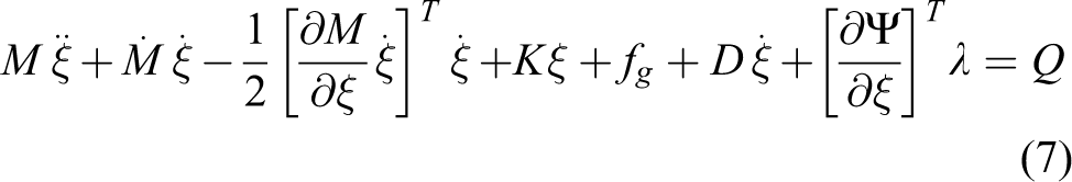
where K and D are modal stiffness and damping matrices of flexible body, respectively. Changes of damping and stiffness only depend on the deformation; therefore, plane motion and rotary motion have no effect on variable performance and energy loss, respectively. fg is generalized gravity, λ is Lagrange multipliers of constraint equations, Ψ and Q are external load, and Kξ and
The shift manipulator dynamics model
The shift manipulator mechanism is split into three open chain mechanisms. The open chain of shift manipulator is shown in Figure 4.

The open chain of shift manipulator. (a) Open chain 1, (b) open chain 2, and (c) Open chain 3.
The base coordinates
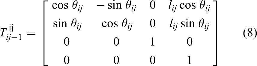
where i is the open chain number, j is the link coordinate system number of the open chain, and θij is the angle of x-axis between

where L is system generalized energy, K is system kinetic energy, and P is system potential energy. For the open chain 1 whose base coordinate is O1, the kinetic energy

where I11 and I12 are the moment of inertia of l11 and l12, θ 11 and θ 12 are the joint angles, m12 is the mass of the rod l12, and v12 is the centroid velocity of the rod l12.


For the open chain 2 whose base coordinate is O 2, the kinetic energy is

where I21 and I22 are the moment of inertia of L21 and L22, θ 21 and θ 22 are the joint angles, m12 is the mass of the rod L22, and v22 is the centroid velocity of the rod L22.


For the open chain 3 whose base coordinate is O 3, the kinetic energy is

where I31 and I32 are the moment of inertia of L31 and L32, θ 31 and θ 32 are the joint angles, m32 is the mass of the rod L32, and v32 is the centroid velocity of the rod L32.


The kinetic energy of the rod lpc
where mpc is the mass of the rod lpc. The total system potential energy P = 0, after it is brought into the Lagrange equation (10), the generalized energy is

The drive torque of the joint O2 and O3 is

The mechanical leg dynamics model
The mechanical leg dynamics model is established by the Lagrange equation (10). The system kinetic energy K and potential energy P are

where I 1, I 2, and I 3 are the moment of inertia of l 1, l 2, and l 3, respectively. Δx is the motion displacement of the electromagnetic linear motor and g is acceleration of gravity. m1, m2, and m3 are the mass of the rod l 1, l 2, and l 3, respectively. After they are brought into the Lagrange equation (10),

The driving force of the mechanical leg
Flexible multibody dynamics model
Flexible multibody system generally consists of a rigid body and a flexible body. The collaboration simulation with ADAMS and HYPERMESH is conducted in this article considering the dynamic behavior of the mechanism motion. The analysis results of ADAMS provide boundary conditions of HYPERMESH. The flowchart of flexible multibody system collaboration simulation is shown in Figure 5. Rigid multibody dynamics model of the direct-drive vehicle robot driver is shown in Figure 6.
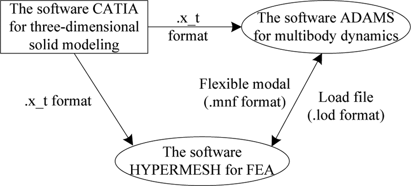
Flowchart of flexible multibody system collaboration simulation.
Rigid multibody dynamics model of the direct-drive vehicle robot driver.
Flexible body model is used for slender and small stiffness part, and rigid body model is used for large stiffness part. Therefore, the shift manipulator is as flexible, and the mechanical legs of throttle and brake and clutch are as rigid. The discrete finite element of rigid multibody dynamics model is established in order to generate modal neutral file used for flexible multibody dynamics analysis. The generation process of the modal neutral file for the flexible multibody dynamics model is as follows. Tetrahedral unit SOLID45 is selected. Steel is selected as the material of the direct-drive vehicle robot driver. The material elastic modulus is 210 GPa, Poisson’s ratio is 0.269, and the density is 7850 kg/m3. Since SOLID45 has a high accuracy, six meshing division is adapted so that it can ensure sufficient accuracy. The mechanical base and the electromagnetic linear motor are connected by Boolean operations. Then, they are fixed on the ground by fixed joint. The slide, the connecting rod, and the pin are fixed together by fixed deputy. The linear motor and the slider are fixed by fixed deputy. The motion way of the slider is determined by mobile deputy. After the modal neutral file is generated, ADAMS/Flex is embedded to ADAMS. The flexible model is imported into ADAMS to replace the original rigid body. The flexible multibody dynamics model is shown in Figure 7.

Flexible multibody dynamics model.
Results and analysis
Simulation comparisons of rigid multibody and flexible multibody
The displacement comparisons of rigid multibody and flexible multibody for the shift manipulator in the direction of gear shifting and gear selecting are shown in Figure 8. The stroke of flexible multibody for the shift manipulator is slightly smaller than that of rigid multibody. In the direction of gear shifting, the stroke of rigid multibody is 205.27 mm and the error of stroke is 5.27 mm, and it is more than the required error that is 2 mm. The stroke of flexible multibody is 198.77 mm and the stroke error is 1.23 mm, which can meet the performance requirements of the motion precision.
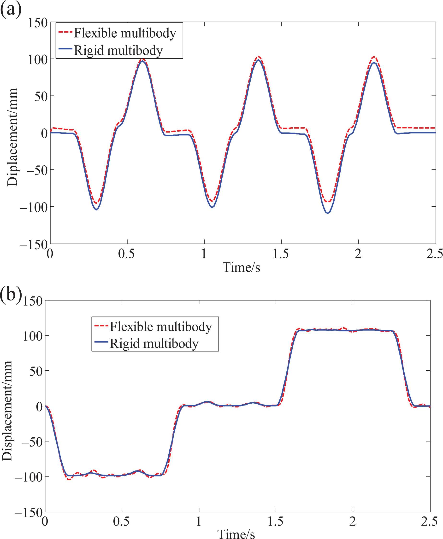
The displacement comparisons of the shift manipulator. (a) The gear shifting and (b) the gear selecting.
The speed comparisons of rigid multibody and flexible multibody for the shift manipulator in the direction of gear shifting and gear selecting are shown in Figures 9 and 10. In the direction of gear shifting, the maximum speed of rigid multibody is 0.467 m/s and that of flexible multibody is 0.445 m/s. In the direction of gear selecting, the maximum speed of rigid multibody is 0.53 m/s and that of flexible multibody is 0.512 m/s. The maximum speed of flexible multibody is smaller than that of rigid multibody. After taking full consideration of the flexibility, the results of the flexible multibody system accurately reflect the actual motion characteristics.

The speed comparisons of the shift manipulator in the direction of gear shifting. (a) The speed curve of gear shifting and (b) partial magnification of gear shifting speed.

The speed comparisons of the shift manipulator in the direction of gear selecting. (a) The speed curve of gear selecting and (b) partial magnification of gear selecting speed.
The movement trajectory curve of the shift manipulator with flexible multibody is shown in Figure 11. X-coordinate axis is the direction of the gear shifting and Y-coordinate axis is the direction of the gear selecting. The square area with dotted line is the 200 × 200 mm movement area of the shift manipulator, and the solid line is the movement trajectory of the shift manipulator. Within the range of the stroke, the movement trajectory of gear shifting and gear selecting is basically straight. Outside the scope of the stroke, the movement trajectory of gear shifting is basically arc.
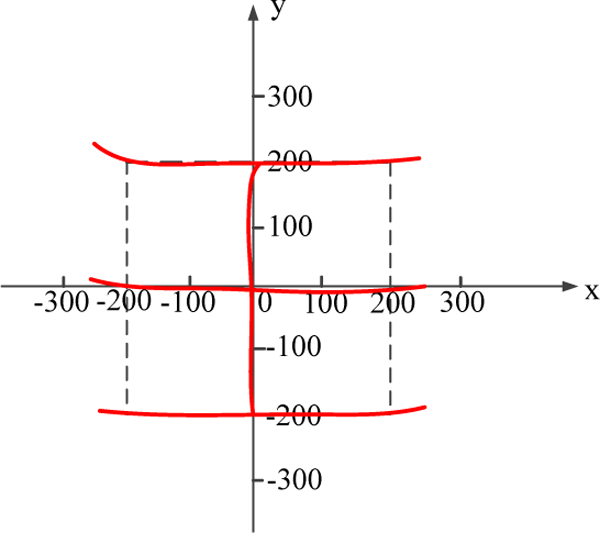
The movement trajectory curve of shift manipulator with flexible multibody.
The movement error curve of the shift manipulator with flexible multibody is shown in Figure 12. The movement error of gear shifting is the displacement in the direction of gear selecting during the process of gear shifting. The movement error of gear selecting is the displacement in the direction of gear shifting during the process of gear selecting. The maximum movement error of gear shifting is 1.763 mm, and that of gear selecting is 1.776 mm, which can meet the requirements of the movement error that is within ±2 mm. The shift manipulator with flexible multibody can achieve the mechanical decoupling between gear shifting and gear selecting, so that it can drive the shift lever to complete the shifting action.

The movement error curve of shift manipulator with flexible multibody. (a) The movement error of gear shifting and (b) the movement error of gear selecting.
Simulation for the mechanical leg
The dynamic characteristic curve of the throttle mechanical leg is shown in Figure 13. The maximum displacement is 771 mm, the minimum displacement is 571 mm, and the output stroke is 200 mm. Assume that the direction of pressing the throttle pedal is positive. The maximum motion speed of the throttle mechanical leg is 0.44 m/s. The maximum output force is 100 N. They can meet the performance requirements.
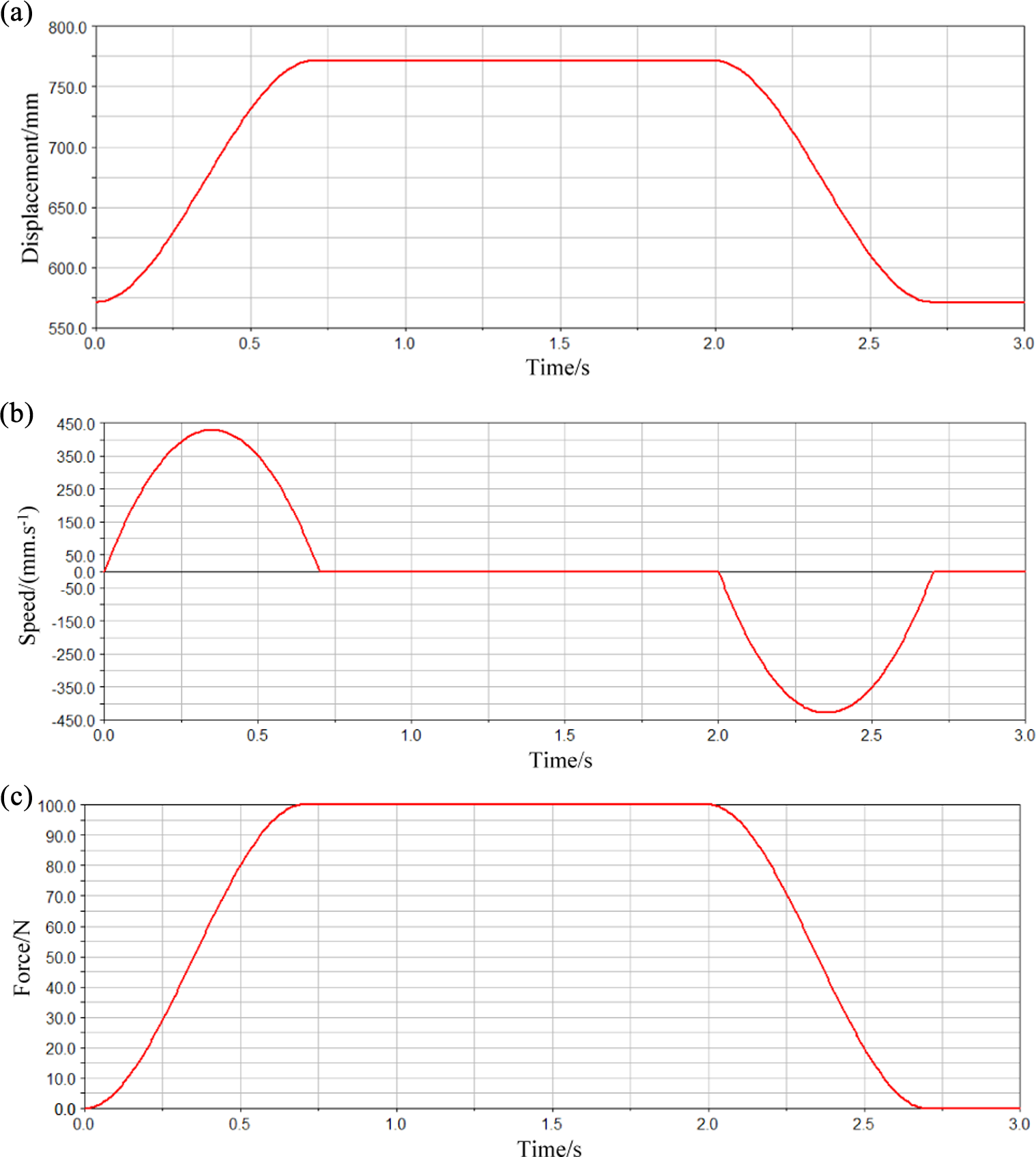
The dynamic characteristic curve of the throttle mechanical leg. (a) The movement displacement, (b) the motion speed, and (c) the output force.
The dynamic characteristic curve of the brake mechanical leg is seen in Figure 14. The maximum displacement is 811 mm, the minimum displacement is 571 mm, and the output stroke is 240 mm. Assume that the direction of pressing the brake pedal is positive. The maximum speed of the brake mechanical leg is 0.3 m/s. The maximum force of the brake mechanical leg is 400 N. They can meet the requirements of performance.

The dynamic characteristic curve of the brake mechanical leg. (a) The movement displacement, (b) the motion speed, and (c) the output force.
The dynamic characteristic curve of the clutch mechanical leg is shown in Figure 15. Assume that the direction of pressing the clutch pedal is positive. The maximum speed of the clutch mechanical leg is 0.35 m/s. The maximum force of the clutch mechanical leg is 400 N. In the period of 0–1 s, the clutch is quickly pressured; in the period of 1–2 s, the clutch quickly returns to the initial engagement position; in the period of 2–3 s, the clutch slowly goes through the engagement area; and in the period of 3–4 s, the clutch quickly goes through the neutral shift area, which can meet the requirements of design.

The dynamic characteristic curve of the clutch mechanical leg. (a) The movement displacement, (b) the motion speed, and (c) the output force.
Experimental validation
To further verify the effectiveness of the presented model of the direct-drive vehicle robot driver with flexible shift manipulator and rigid mechanical legs, in line with the required national standards of emissions durability, 20 the vehicle durability emission test is performed by the direct-drive vehicle robot driver. The test process is shown in the study by Chen and Zhang. 1 The direct-drive vehicle robot driver installed in a cab of test vehicle is seen in Figure 16.

The robot prototype and vehicle test. (a) The robot prototype and (b) the vehicle test.
The comparisons of displacement and speed between simulation and experiment from second gear to third gear are shown in Figure 17. In Figure 17, the simulation is the results of flexible multibody model. The figure shows that the entire shift process of the test vehicle transmission is manipulated by the shift manipulator from second gear to third gear. The shift manipulator first moves the shift handle out of second gear to neutral gear, then gear selecting operation is conducted, where gear shifting displacement approximately remains constant. The fluctuation of experiment results is due to the installation error between the shift manipulator and shift handle and the internal friction from test vehicle transmission during the shift process. After the gear selecting operation, the shift handle is in neutral gear. Then, the gear shifting operation is conducted. The shift manipulator manipulates the shift handle to complete the action of hanging in third gear from neutral gear. The maximum shift speed between simulation and experiment is close, and the shift speed change between simulation and experiment is also basically close. The effectiveness of the multibody dynamics model is verified by the comparative analysis.
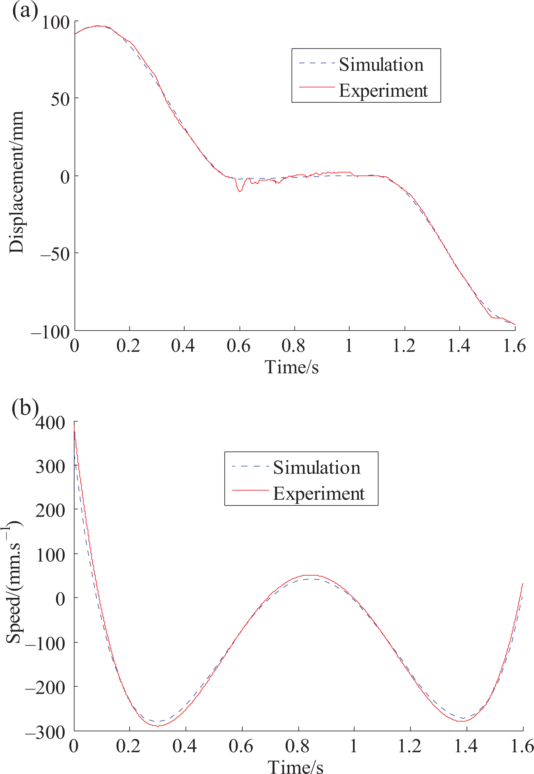
The comparisons of displacement and speed. (a) Displacement comparison and (b) speed comparisons.
The speed tracking curve of the direct-drive vehicle robot driver is shown in Figure 18. The test results of the shift manipulator are shown in Figure 19. The opening degree of the mechanical leg consisting of the throttle, brake, and clutch is shown in Figure 20. Figures 18 to 20 show that the direct-drive vehicle robot driver with flexible shift manipulator and rigid mechanical legs can realize vehicle start, vehicle speedup, vehicle shift, vehicle constant speed, and vehicle slowdown using the coordinated control of the multiple manipulators. During the automated driving process, the transition between the different working conditions is smooth, the repeat ability of speed tracking results is good, and the speed control tolerance is not more than ±2 km/h, which can meet the performance requirements of national test standards.
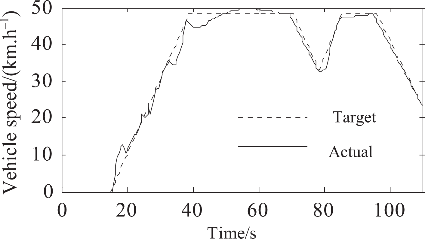
The speed tracking curve of the direct-drive vehicle robot driver.

The test results of the shift manipulator.
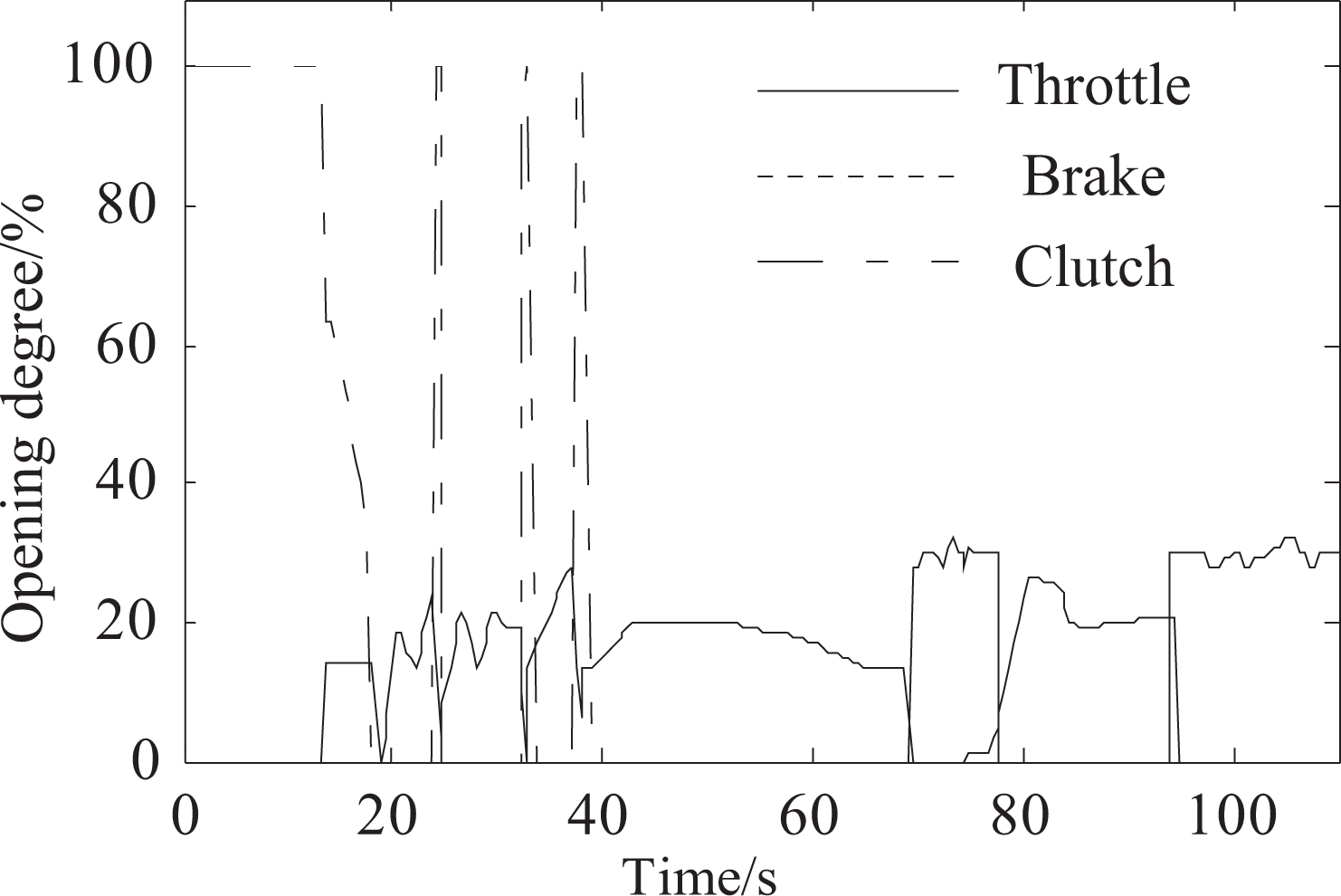
The opening degree of the mechanical leg.
The opening degree of the throttle, brake, and clutch is 0% when the mechanical leg of throttle, brake, and clutch is not at all under pressure. When the mechanical leg is pressed the end, it is 100%.
Conclusions
Collaborative dynamics modeling of flexible multibody and rigid multibody for the direct-drive vehicle robot driver is presented in this article. Spatial dynamic equations of the direct-drive vehicle robot driver are obtained based on multibody system dynamics. The shift manipulator dynamics model and the mechanical leg dynamics model are established based on the multibody dynamics equations. After establishing a rigid multibody dynamics model and conducting finite element mesh and finite element discrete processing, a flexible multibody dynamics model of the direct-drive vehicle robot driver is established. The comparisons of the simulation results between rigid multibody and flexible multibody for the shift manipulator are conducted. The movement trajectory of the shift manipulator with flexible multibody is analyzed. Besides, the effectiveness of the mechanical leg with rigid multibody is verified by the simulation results. The experimental is conducted using the direct-drive vehicle robot driver designed by the proposed model.
Simulation results demonstrate that the flexible multibody dynamics model can reflect the dynamic motion characteristics really and exactly as well as the prediction of the performance of the direct-drive vehicle robot driver. After taking into consideration of the flexibility, the simulation results of the flexible multibody system accurately reflect the actual motion characteristics. The proposed approach will provide a method to analyze the design and optimization of the direct-drive vehicle robot driver. Experiment results show the direct-drive vehicle robot driver with flexible shift manipulator and rigid mechanical legs can realize the start, speedup, shift, constant speed, and slowdown of vehicles. And the speed control tolerance can meet the performance requirements of the national test standards.
Footnotes
Declaration of conflicting interests
The author(s) declared no potential conflicts of interest with respect to the research, authorship, and/or publication of this article.
Funding
The author(s) disclosed receipt of the following financial support for the research, authorship, and/or publication of this article: This project is supported by National Natural Science Foundation of China (grant no 51675281 and 51205208), Six Talents Peak Project of Jiangsu Province (grant no 2015-JXQC-003), and The Fundamental Research Funds for the Central Universities (grant no 30916011302 and NJ20160037).