
Abstract
In this article, a new adaptive coordinated motion control approach is introduced for a dual-arm free-floating space robot. This adaptive algorithm is used for the post-capture of a large noncooperative target with joint-limit avoidance and uncertain dynamic parameters. To overcome the problem of dynamics coupling between the space base, its manipulators, and the target, we develop a dual-arm space robotic system. One arm is used to complete the capture task and the other is used to counteract the disturbance to the space base. In this case, a new coordinated motion control law is derived based on reaction null space control. An improved joint-limit avoidance algorithm is implemented for large noncooperative target capture; otherwise, a significant base disturbance may result if the joint-limit constraints are not explicitly considered. Based on momentum conservation, the linear regression form of the estimation problem is obtained, and we further identify the unknown inertial parameters of the target. Finally, the simulation results demonstrate the effectiveness of the proposed algorithm.
Keywords
Introduction
With the development of astronautic technology, space robots will undertake additional tasks in space exploration. Their main missions to date have been to capture and repair noncooperative space objects or debris and to support astronauts in replacing or assembling components on space stations. Therefore, many countries have paid significant attention to the development of space robotic technologies. The SUMO/FREND project and the Phoenix Program 1 exemplify typical orbital applications of space robots. The main characteristics of the two projects are that the space robots have more than one manipulator and that the inertial parameters of the target spacecraft are much larger than those of the robot.
To describe the interactive relationship between a space robot and the target, on-orbit capture missions can generally be divided into three phases 2 : pre-capture, capture, and post-capture. In the pre-capture phase, a space manipulator is controlled and approaches the target by gradually following the motion of the target. At the instant of capture, the end effector of the space manipulator makes contact with the target until the gripper is closed. The primary challenge in this phase is to minimize the interaction between the end effector and the target. In the post-capture phase, the end-effector of the space manipulator firmly captures the target, and the space robot must dampen the motion of the target. The initial angular momentum of the captured target is dampened using thrusters or reaction wheels. In this article, we address the problems that arise in the post-capture phase. The main topic that is presented in this article is minimization of the reaction moment of the space base after capturing a large noncooperative target satellite that initially has angular momentum. The momentum may cause the system to become unstable. This task is necessary since the antennas of the servicing base must be pointed toward the Earth and, therefore, the base attitude must be maintained.
For a successful capture of a noncooperative target, the motion of the entire system, including the space base, the space manipulators, and the target, should be considered. Therefore, many studies have been conducted on angular momentum management during the post-capture phase. Dubowsky and Torres 3 developed a planning method known as an enhanced disturbance map for simultaneous control of space manipulator motion and spacecraft attitude. Yoshida et al. 4 introduced reaction null space (RNS) control to stabilize the base attitude, which has proven useful in the ETS-VII project. Recently, Xu et al. 5 proposed a coordinated motion control algorithm for a dual-arm space robot to plan zero-disturbance end-effector paths. However, it should be noted that the success of the approaches mentioned above relies on the accuracy of our knowledge of the target’s dynamic parameters, such as mass and moment of inertia.
Two main strategies have been developed to address inertial parameter uncertainties. The first is a two-stage approach, which involves first estimating the uncertain parameters and then designing a controller with the estimated parameters. The second is to develop the adaptive control methods and algorithms for the uncertain parameters. Previous work on the related problems includes that of literature. 6 –12 In the studies by Atkeson et al., 6 Jia et al., 7 and Yoshida and Abiko, 8 methods were proposed to identify the inertial parameters of a target handled by a space manipulator. These authors derived a parameter identification procedure from the momentum conversation equations, which is known as distributed momentum control (DMC) and is unique to space manipulator systems. Adaptive control techniques are proposed in literature 9 –12 to address the problem of end-effector motion control while holding an unknown payload. However, none of these approaches have resolved the issues arising when capturing a large and tumbling target. In this article, by incorporating online estimation and adaptive control into a dual-arm system, we design a new adaptive coordinated motion control scheme based on the adaptive RNS (ARNS) algorithm.
With the developed dual-arm space robot system, an extension of the ARNS algorithm is presented in the consideration of joint-limit constraints. The joint limits must be avoided for a practical implementation of the proposed ARNS scheme on space manipulators. Otherwise, the space manipulator may reach its physical joint limits, and a significant base disturbance may occur, which would lead to disastrous results. In this article, the ARNS scheme is reformulated and integrated with the target’s parameter identification procedure. The recursive least squares (RLS) algorithm is implemented to identify the unknown inertial parameters, namely, the mass, moment of inertia of the target, and center of the mass. To accelerate the convergence rate of the tracking errors, a PD-type iterative learning control law is developed using the online parameter identification.
The principal differences of the proposed procedure from previous related studies can be stated as follows: The ARNS motion control scheme is expanded from a single-arm space robot to a dual-arm space robot, in which both arms execute ARNS motion. This adaptive scheme is employed to stabilize a large inertial target that carries unknown momentum without the use of reaction wheels or jet thrust. To guarantee the ARNS motion, an improved joint-limit algorithm is implemented, which can expand the motion range of the joint. Based on momentum conversation, we obtain the linear regression form of the estimation problem. Using the online parameter estimation, a PD-type iterative learning control law is developed to speed up the convergence of the tracking errors.
This article is organized as follows. “Dual-arm space robot system” section describes the kinematic and dynamic modeling and coordinated motion equation of a dual-arm, free-floating space robot. Then, the ARNS algorithm for a dual-arm space robot is reformulated with joint-limit avoidance. Next, the estimation algorithm for the identification of the inertial parameters is presented. Next, a study of a PD-type iterative learning controller is conducted to incorporate the inertial parameters of the target. The proposed method is validated with some simulation examples in “Simulation study” section. “Conclusion” section provides the conclusions and recommends directions for future work.
Dual-arm space robot system
Basic assumptions
During the operation, the space robot is in free-floating mode. We assume that The system is composed of rigid bodies only, and the origin of the inertial frame ΣI is located at the center of mass of the entire system. After the manipulator grasps the target, the target is fixed to the end-effector; thus, there is no relative linear motion between the end-effector and the target. The initial linear and angular momenta of the space robot system is zero. No external forces or torques are exerted on the entire system (space robot and target). The reaction wheels or other momentum exchange devices are not considered in this article. The total momentum of the system is conserved in this situation.
Kinematic and dynamic modeling of a dual-arm space robot
The dual-arm space robot consists of a space base (spacecraft) and two arms. One arm is the mission arm (arm-a), which is used to complete space tasks, such as capturing and assembling; the other arm is known as the balance arm (arm-b), which is used to compensate for the reaction motion of the mission arm, as shown in Figure 1.

Dual-arm space robot system.
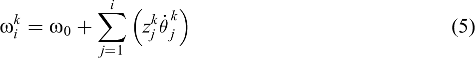
An alternative approach to establish the model of a dual-arm space robot is described in the study by Yoshida et al. 13 From Figure 1, the position of body i and end-effector in arm-k (k = a, b) are, respectively, as follows


Differentiating the two sides of equations (1) and (2), the linear and angular velocity equations are obtained as follows


Under assumption (d), the total momentum of the space robot system is conserved, implying that the linear and angular momentum of the space system (P, L) remains constant. The elements of the matrix are explicitly described in the study by Yoshida et al. 13


where
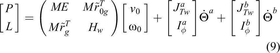
Then, equation (9) can be rearranged as
where

and
The linear velocity of the base can be cancelled out by the first three rows of equation (10); then, the angular momentum conservation equation can be written as

With assumption (c), there is no initial angular momentum (L = 0) and no attitude disturbance (ω0 = 0)

Since arm-a is used as the mission arm,

where
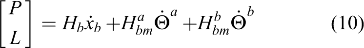
As per the kinematic equations presented above, the total kinetic energy can be written as


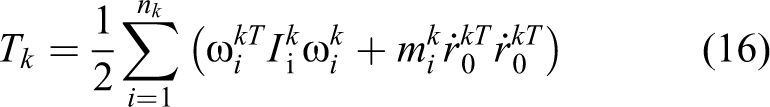
When there are no external forces exerted on the system, the dynamic equation can be obtained as


ARNS with joint-limit avoidance
For the time-varying systems, when there are parameter uncertainties in the system, one way to reduce the uncertainty is to use adaptive control algorithm. In this section, based on the concept of an RNS, an adaptive coordinated motion control of the dual-arm space robotic system is constructed, to minimize the disturbance transferred to the base with consideration of joint-limit constraints.
Formulation of ARNS
To address the problems of post-capture of a tumbling target, an adaptive reactionless motion control for a single-arm space robot is introduced in the studies by Nguyen-Huynh and Sharf 14 and Nenchev et al. 15 The main drawback of previous studies is that they consider only small inertial targets. For large targets, the performance is decreased significantly. 16 To address this limitation, we expand in this section the adaptive reactionless motion algorithm from a single-arm model to a dual-arm model. In this dual-arm space robot system, arm-a is designed to accomplish the capture task and arm-b is used to compensate for the attitude disturbance due to the motion of arm-a; thus, the mapping relationship between the two arms can be formulated. The trajectory of the balance arm is generated by that of the mission arm. From equations (12) and (13), specifically under ideal conditions, the null-space solutions for the joint rates of arm-a and arm-b can be obtained as


where
For the general case in which the initial system angular momentum is nonzero and the tumbling target has angular momentum Lt, equation (11) can be restated as follows

where Lm is the angular momentum of the space robot before capture. The matrix

where L = Lm + Lt is the angular momentum of the entire system after capture and


Substituting for


where

where

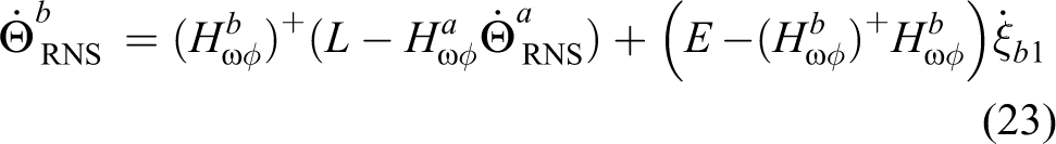
The motion generated by equation (28) does not cause any rotational motion of the base. Since the matrix Hω is always invertible and assuming Hωφ has a full row rank, equation (28) can be rewritten as

or, more succinctly

where
Thus, equation (31) is the foundation of the RNS control scheme for a dual-arm space robot system. Since the captured target changes the dynamic properties of the arm in an undetermined way, the reference joint rate

where
As per the studies by Nguyen-Huynh and Sharf
14
and Paleologu et al.,
17
using the base angular velocity and joint rates at time t, the RLS approach is employed to compute the updates for

where


With the estimates

where
Improved joint-limit avoidance strategy
In order to avoid joint limits, the gradient projection method is employed within the adaptive control scheme. According to the study by Nguyen-Huynh and Sharf,
14
the arbitrary vector
Then,

where k is a user-defined positive constant,

This algorithm attempts to restrict the joint angle around the middle position of the given joint’s range. Thus, it cannot fully utilize the entire motion range of the joints.
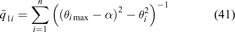
To overcome this shortcoming of the joint-limit algorithm in the study by Nguyen-Huynh and Sharf, 14 we propose an improved joint-limit algorithm that allows a wide range of motion without violation of the joint limit.
In Figure 2, α is the safety angle near the boundary, and


Concept of the improved joint-limit algorithm.
The differential of qi with respect to θi is set as

where

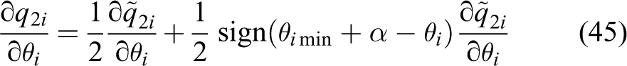
The equations imply that the differential


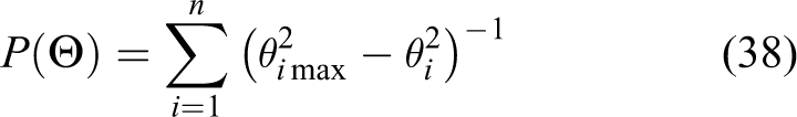
In such a scenario, the joint-limit potential function is
Thus, joint-limit avoidance is guaranteed, and the RNS motion can be obtained by projecting the gradient of the performance criterion onto the null-space of matrix Hωφ.
Parameter identification of a large noncooperative target
The momentum-based parameter identification for a space manipulator is formulated in this section. In the following derivation, it is assumed that shortly after the manipulator grasps the target, the target is fixed to the end-effector, and hence the inertial parameters of the last link of arm-a are altered (see Figure 3). Under this assumption, the unknown parameters to be identified are the mass, the position of the center of mass, and the inertia moment. 18

Part of a target captured by the space robot.
After capturing the target, the linear and angular momentum equations, equations (7) and (8), are rewritten by involving the unknown parameters of the noncooperative target


where ωt is the angular velocity of the target (with ωe = ωt) and rt is the position vector of the mass center of the target to the origin of inertia coordinate, which can be decomposed as


where Ra is the rotation matrix from frame Σn to ΣI. Substituting for rt and

Since the momentum of the entire system is conserved, the increment of the total momentum, as the system evolves from the configuration at time tk to another configuration at the instant tk+1, is zero. This process results in the following


If Δt tends to an infinitely small value,

In equations (55) to (57), ΔP and ΔL denote the increment of the linear and angular momentum between time tk and tk+1. Combining equations (55) to (57) into matrix form and factoring out the vector of unknown parameters, the standard linear equation for the estimation problem is obtained as follows

where

After the target is fixed to the end-effector, the angular velocity ωt is equal to ωe.
PD-type iterative learning control
After having calculated the ARNS motion for the joints, the free-flyer requires a controller to determine the torques to apply on the joints to execute the desired movement to perform the task. With the uncertainties in the large target, some questions arise, that is, is it possible to design a controller with the identified information of the target? And in addition, how to learn the system knowledge through a simple control approach? Taking this into consideration, a PD-type iterative learning control structure is proposed.
Recall the dynamic model for the dual-arm space robot system in equation (17). A modified version of the PD control law can be obtained


In these equations,
However, the scheme implemented for the base-manipulator-target system will be relatively complex, as it depends on the accurate knowledge of the dynamic model. To remedy such a shortcoming, an iterative learning control is introduced, which causes


where τ(t−1) is the output of the previous time step and employed as the input of the current time step and
To analyze the stability of the proposed control law, a scalar Lyapunov function is introduced as

The difference of V(t) is given by

Since it is a discrete dynamic system, we can obtain a linear approximation of e(t+1) by

where

Assuming that the control algorithm is implemented at a sufficiently high sampling rate, we obtain

Recall that Kp and Kv are the proportional control gain matrix and the derivative control gain matrix, respectively, that are diagonal positive definite. Once initializing Kp and Kd with
The proposed ARNS scheme with joint-limit avoidance requires measurements of the base angular velocity ω0(t) and the current joint rates
Step 1. Initialize the system based on pre-capture parameters,
Step 2. Measure Θ(t),
Step 3. Compute
Step 4. Compute
Step 5. Using
Step 6. Compute
Step 7. Update τ(t) to generate the appropriate joint torques.
Step 8. t = t+Δt, return to step 2, until finished.

ARNS control scheme with joint-limit avoidance and estimation of inertia parameters. ARNS: adaptive reaction null space.
In this way, the parameter matrix
Simulation study
The simulation study aims to verify the capability of the proposed adaptive coordinated motion control scheme to minimize the disturbance to the base with joint-limit avoidance. The verification is presented using a dual-arm planar space robot; each arm has three degree of freedom. The target is realistically captured by the manipulator, and the target is assumed to be firmly held by the gripper mechanism as illustrated in Figure 5.

Dual-arm space robot with captured target.
The space manipulator initially has no momentum, and the target is tumbling with an initial angular velocity of ωt = 1.15°/s. The initial adaptation gain matrix is defined as Q(0) = diag[500, 500, 500]; it will be reset when Q(t) ≥ 600 or Q(t) ≤ 1. The forgetting factor for the RLS algorithm is λ = 0.99. The step size is T = 0.005 s.
The dynamic model of the space robot and the target are created in MATLAB/SimMechanics with S-functions. The relevant parameters of the base, links, and initial states employed in this study are summarized in Tables 1 and 2. Especially, the noncooperative target is much larger than the space robot. The mass and inertia are assumed to be four times as large as the mass and inertia of the servicer (refer to Table 3).
Parameters for dual-arm space robot.

Initial state for dual-arm space robot.

Parameters for noncooperative target.

Case A: ARNS motion without joint limits
Before the estimation of the parameter, the accuracy of the simulation platform is first ascertained by examining the momentum conservation of the system during the ARNS motion. In Figure 6, the system angular momenta are illustrated, depicting the process of the angular momentum distribution as the total angular momentum remains constant. The process of the distribution is slow because the target is much larger than the space robot. Figure 7 shows the ARNS motion control maintaining the base attitude while one arm holds the large noncooperative target. Minimum base disturbance is produced by ARNS motion. In Figure 8 and Figure 9, the corresponding results are shown, which one can observe the joint motions. These results verify the accuracy of the simulation platform and its suitability for testing the proposed control concept.

Angular momentum of the system.

Disturbance to the base without joint limit.

Joint angles without joint limit.

Joint rates without joint limit.
The results for the ARNS algorithm without joint limits that are presented here demonstrate the important role of the proposed ARNS scheme in the post-capture phase. Without joint-limit constraints, arm-b joint 1 may reach 142.5°, and the maximum disturbance to the base is approximately 0.002°.
Once the capture is established, the momentum-based parameter identification method is executed. The motions generated by the ARNS scheme provide the measurements required for solving the parameter identification problem stated in equation (58). The estimation results are shown in Figure 10 (a logarithmic (base 10) scale is used for the X-axis, t = 20 s) and Table 4. Within 0.1 s after capture, the parameter estimates for mt, bt, and It converge to their real values. The availability of inertial parameters for the entire base-manipulator-target system facilitates the post-capture stabilization task, since precise knowledge of space manipulator dynamics is necessary for many model-based control algorithms, such as trajectory control, optimal control, or DMC.

Estimations of inertial parameters.
Results of identification parameters.

Case B: ARNS motion with improved joint-limit avoidance
The improved joint-limit avoidance algorithm is also employed with the ARNS motion control. The joint-limit constraints of the arms are presented in Table 5.
Joint-limit constraints for the dual-arm.

The results for joint-limit avoidance are shown in Figures 11 to 15. Figure 11 presents the original joint-limit avoidance algorithm for arm-b joint 1. The joint moves around the medium position of the range. Though this algorithm manages to protect the joint from violation of the joint limit, it does not fully use the entire motion range. The improved joint-limit avoidance algorithm overcomes this shortcoming. In Figure 12, the joint moves freely in the safe area. When it passes the safe line and approaches the joint limit, it is driven to return. The maximum joint angle it reached is 58.3°. In fact, comparing the results in Figures 11 and 12, it is apparent that the improved joint-limit scheme expands the motion range. In Figures 13 and 14, the other joint angles are shown. A comparison of the joint rates profiles in the square frame in Figure 15 reveals that when the first joint turns around to escape the joint-limit area, the second and third joints attempt to compensate for the change of the first joint. This response demonstrates that the joint-limit avoidance task of the proposed control law is completely satisfied. As shown in Figures 12 and 16, during the time period of 10–14 s, the potential function is forced to decrease whenever the joint approaches its limit; the function acts as a penalty function that returns a high weight under this scenario.

Original joint-limit avoidance algorithm.
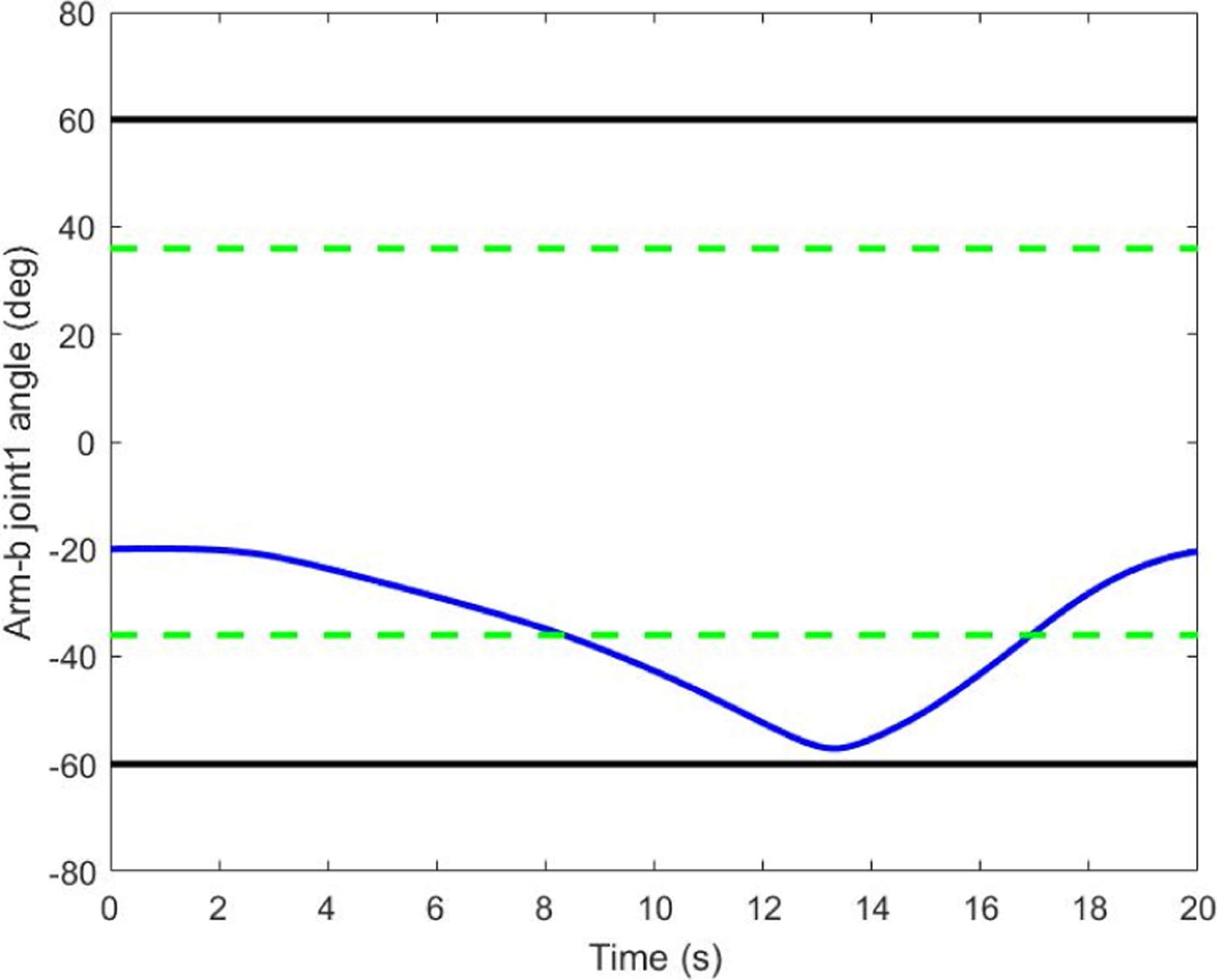
Improved joint-limit avoidance algorithm.

Arm-b joint 2 and joint 3 angles.
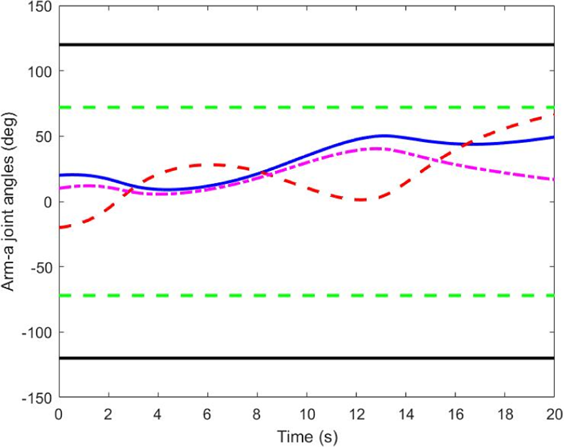
Arm-a joint angles.
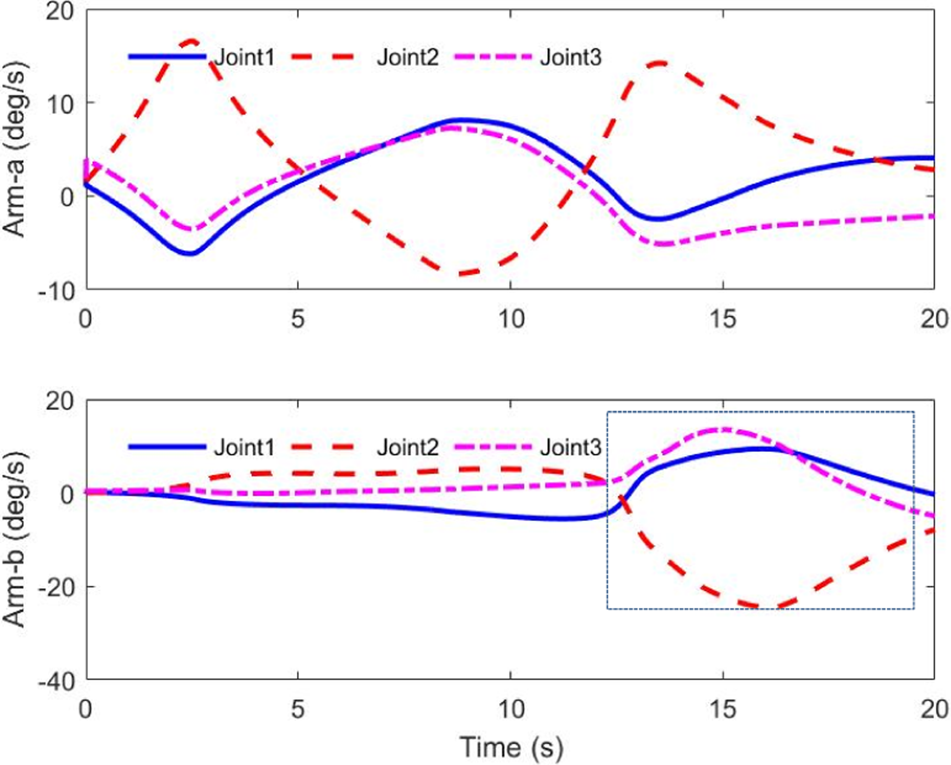
Joint rates of space robot.

Potential function.
In this test case, the attitude disturbance to the base is shown in Figure 17. Compared with that shown in Figure 7, the performance of the base response worsens (O(10-2) versus O(10-3)), especially when the joints approach their limits. When the joints remain in a safe area, no significant difference is observed in the base response.

Disturbance to the base with joint limit.
Case C: Controller analysis
For evaluating the performance of the proposed PD-type iterative learning controller, the torques of the system are studied here. Note that the PD-type iterative learning control gains are the same with that of the PD controller. They are presented in Table 6. The positive number is defined as ε = 0.001. Once we have e ≤ ε, the learning process stops and the controller switches from PD-type iterative learning control to PD control.
The gains of the controller.

Figures 18 and 19 depict the torque differences between the PD control and the PD-type iterative learning control. The error profiles of the PD controller and PD-type iterative controller are shown in Figures 20 and 21. To clearly show the convergence rate, a logarithmic (base 10) scale is used for the X-axis (t = 20 s). The performance improvement is unambiguous, where the convergence time is t = 0.5 s and t = 0.08 s, respectively. The effectiveness of the PD and PD-type iterative learning control law can be explained as follows: Before the iterative learning control is employed, nothing is known about the target in the control scheme; thus, the system can be treated as a black box. After the first iteration, the PD-type iterative learning control law obtains some dynamic information about the target, and the system becomes a gray box. As the iterations go on, more knowledge of the inertia parameters is obtained and added to the control law. Therefore, the PD-type iterative learning control law offers a faster convergence rate than that of the typical PD control, which is advantageous for applications involving the capture of a large noncooperative target.

PD control law.

PD-type iterative learning control law.

Joint rates error of PD control.

Joint rates error of PD-type iterative learning control.
Conclusion
In the course of on-orbit servicing, the tumbling target was assumed to be much larger than the space robot, which meant that the uncertainties of the inertia properties of the target would degrade the control performance and the compound stabilization. To address this problem, this article presented a new adaptive coordinated motion control for a dual-arm space robot. The advantage of this control scheme was that it was designed for the capture of a large unknown tumbling target. With the proposed adaptive coordinated motion control strategy, three relevant problems of post-capture control of a dual-arm space robot were addressed simultaneously: maintaining minimum disturbance to the base by manipulator-target motion, avoiding joint limits, and identifying the target’s properties in real time. A PD-type iterative learning control algorithm was also presented to accelerate the convergence rate of the tracking errors. The simulations revealed that the proposed methods were applicable to a dual-arm space robot supplying on-orbit services.
Based on the proposed methods, several recommendations for further research can be made as follows: The dynamic singularity issue should be addressed for the dual-arm space robot. Due to a lack of the accuracy knowledge of dynamic properties, the singularity problem may be more complex after capturing an unknown target. The closed-chain constraints should be investigated in future. To manipulate a large target, the dual-arm space robot and the target may form a closed-chain system. New planning and control algorithms should be proposed to deal with such constraints. Constructing the experimental test-bed and actual experimental validation of the proposed methods are strongly recommended for future work.
Footnotes
Declaration of conflicting interests
The author(s) declared no potential conflicts of interest with respect to the research, authorship, and/or publication of this article.
Funding
The author(s) disclosed receipt of the following financial support for the research, authorship, and/or publication of this article: This work has been supported by the National Natural Science Foundation of China (61673239), (61703228) and Science and Technology Project of Shenzhen (JCYJ20160428182227081), (JCYJ20160301100921349) and (JSGG20160301100206969).