
Abstract
Mobile articulated robots system composed of tractor and multiple articulated trailers is a nonlinear and underactuated system subject to nonholonomic constraints. The significant achievements of path planning for mobile robots with single segment are very difficult to be applied to it directly. For resolving this problem, the kinematics model is established for the system with three segments connected by nonstandard connection type, as well as its trajectory. Equivalent size is introduced that includes two parameters: the distance parameter being the size for enlarging obstacles and the curvature parameter being the minimum turning radius of system. The distance parameter is used to enlarge obstacles in the environment to shrink the system to be a particle. The planning path adopted by the improved A* algorithm can ensure itself as a collision-free and feasible path as long as the maximum path curvature is no larger than the curvature parameter in free space. The comparisons of simulation result show that the improved A* algorithm makes the quality of path optimized and more suitable than A* algorithm under the complex environment.
Keywords
Introduction
The control of a compact tractor-trailer using an electrical vehicle can improve the working efficiency and increase the load transportation capacity. 1 Mobile articulated robots has become one of the most welcomed and popular electronic devices in automated factories, airport, railway station, and shipping wharf to accomplish the tasks of materials transmission, baggage handling, and goods transshipments. In addition, it is used for many applications with different goals in rescue environments such as reconnaissance, hazard identifications, and victim detection. Therefore, it is considered to have extensive prospect nowadays.
Mobile articulated robot composed of several segments (e.g. tractor and multiple articulated trailers) is a nonlinear and underactuated system subject to nonholonomic constraints. 1,2 Compared with mobile robot with single segment, the study of kinematics and motion control of mobile articulated robots system can be very complicated. In order to implement path planning effectively, it is necessary to establish the corresponding kinematics model, such as tractor-trailer wheeled robot, 3 center-articulated mobile robot, 4 the general one-trailer system, 5 mobile articulated robots with two trailers, 6 articulated tricycle for agriculture, 7 mobile robots with N-trailers, 8,9 and so on. Over the last few decades, a great number of studies have been devoted to path planning for the mobile articulated robots, and different approaches have been proposed. Nayl et al. 10 analyzed the effect of kinematic parameters on a novel proposed online motion planning algorithm for an articulated segment based on model predictive control. Lamiraux et al. 11 dealt with the motion planning and control for the mobile robot Hilare pulling a trailer. Carlos et al. 12 presented a nonlinear feedback control law and a method of path reconstruction for the rear carts for a train-like segment used in dangerous environments.
A* algorithm is a method of path planning in known global environments and also applies to path quadratic programming. 13 For example, a simple but very effectual method is proposed to make the A* algorithm suitable for dynamic local path planning in real time. 14 Trovato and Dorst 15 proposed differential A* algorithm to solve the problem of path planning under the condition of local environmental information changes. However, there are some issues in the A* algorithm and the differential A* algorithm, such as many broken lines and turn times. Moreover, the processing of the differential A* algorithm is complicated and computationally costly. Although product development using improved A* algorithm has been drawing much attention from academics as well as corporate world, research into mobile articulated robots system is still rarely underdeveloped. This article deals with the path planning from an initial position to a goal position for mobile articulated robots. The improved A* algorithm model is established and is compared with A* algorithm to improve the quality of planning path. However, there are some constraints in mobile articulated robots system, such as incomplete constraints in the motions of each segment, the axial angle constraints among the segments, and the steering angle constraint leaded by the steering mechanism of tractor. It is these factors that make the significant results of path planning of single segment mobile robot are very difficult to apply directly to the system. Accordingly, this article elaborates the process of employing equivalent size (ES) to enlarge obstacles in static workspace so as to plan path effectively for this kind of robot.
The remainder of this article is organized as follows. The second section presents the description and analysis of the motion of mobile articulated robots system. The third section focuses on the path planning for the system based on the improved A* algorithm. Simulations of path planning based on the A* algorithm and the improved A* algorithm are performed in “Simulation results” section. Finally, conclusions of this work and the future tasks are given in “Conclusion” section.
Description and analysis of the system motion
Mobile articulated robots system can be categorized into standard link and nonstandard link according to the position of join point. The standard form is defined as the join point lies on the midpoint on rear axle of the former body, and the nonstandard one on the intersection of two connecting rods. Actually, the standard form can be regarded as the special status of the nonstandard form. Mobile articulated robots system with three segments connected by nonstandard form is regarded as research subject in this article, as shown in Figure 1. Kinematics equation is well-known for describing the relations between the system configuration against time or derivative of other variables. The verse kinematics problem is that how to calculate the configuration of each segment with the given control inputs of tractor drive and steering mechanisms. Trajectories of each segment are varied during the movements unless the system moves in a straight line. The width of trajectories swept by the entire system is variable. Therefore, it has brought higher demands to the motion planning. The trajectory is analyzed to provide important reference information for the path planning based on the kinematics equation of the system.

Coordinate system of mobile articulated robots with three segments.
Kinematics model
Suppose that each segment is considered as rigid body with the same width and is symmetric about its longitudinal axis. As the first segment of the system, the tractor has three wheels and the front one plays the role of both driving and directing action. As a nonholonomic system, this system has non-integrable velocities restrictions. The nonholonomic restriction for the first segment is given by
Establishment of the coordinate system
The coordinate system of mobile articulated robots with three segments is shown in Figure 1, in which the reference frame (i.e. the absolute coordinate system) XOY is established firstly with O set as the coordinate origin, and then the coordinate systems of each segment are established; Oi is set as the coordinate origin located within the center of wheels, and it is considered as the reference particle of the segment; Νi is the join point between the ith and the (i−1)th segment; di is the distance from Νi to Oi and ei is the distance from Νi + 1 to Oi; α is the steering angle of the first segment with the counterclockwise direction being deemed as positive; u is the translational velocity of the front wheel of the first segment; vi is the translational velocity of the ith segment; VNi is the velocity of the ith segment; ωi is the steering angular velocity of the ith segment; βi is the angle between xi-axis and X-axis, and ψi is the longitudinal axis angle between the ith and the (i + 1) th segments; and
Establishment of the kinematics model
For the first segment, u, α and v1, ω1 are the control inputs and outputs of the system, respectively. According to the influence of nonholonomic constraints on the system motion and the geometrical relations among the kinematics parameters, the kinematics model between inputs and outputs is obtained as
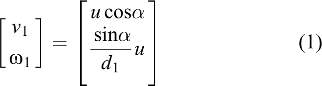
Meanwhile, the configuration parameters and velocity of the first segment are derived

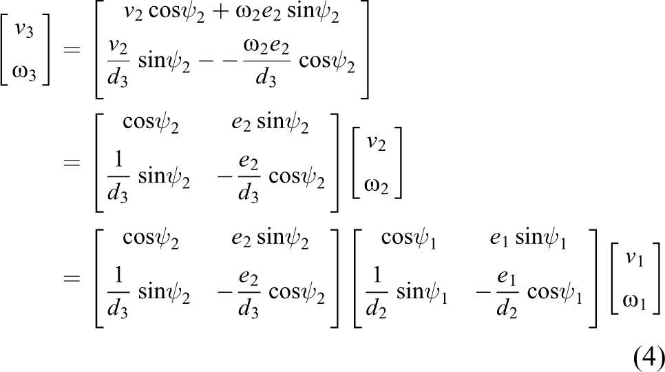
In Figure 1, the relations of speed between the first and second segments can be expressed as

The relations of speed between the second and third segments can be deduced simultaneously as
The independent configuration parameters β2 of the second segment and β3 of the third segment can be expressed separately as


The angles of the adjacent segments and turn angles of each segment satisfy the following relations

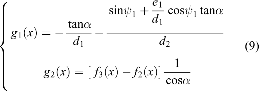
Accordingly, the kinematics equation of the system in matrix form is obtained as

in which, g1 (x) and g2 (x) can be expressed as
Description and analysis of system trajectory
It is necessary to study the system trajectory to obtain a reasonable path planning for mobile articulated robots system. The trajectories of all segments are basically the same when the system reaches its destination in straight, while a set of trajectory family is produced because of the included angle between the segments when the system run along an arc to form a band path. 16,17 The width of band path determines the breadth of the system that ensures the safe operation. Therefore, the change rule of motion trajectories is described and analyzed accurately to plan an optimal and feasible path, rather than plan path by using the traditional method, namely considering the system as a particle directly.
The location coordinates of each segment wheels at any time can be obtained by equations (2), (5), and (6). Accordingly, the trajectories of each segment can be determined within its path range with a given tracking path of the first segment to determine the band path of the whole system. Suppose that the first segment tracks the path described as

The movement trajectories of the reference nodes of the second and third segments can be expressed separately as


Choosing the configuration of the system when the first segment begins to follow a given curve as the initial condition, the configuration at any time instant can be solved from the nonlinear differential equations (2), (5), and (6) using Runge–Kutta method. Then the motion trajectories of the system are obtained after solving equations (10), (11), and (12) using numerical calculations, as presented in Figure 2.

Band path of mobile articulated robots system with three segments.
Now that the trajectories are analyzed and the band path is described based on the kinematics model of the system with three segments. The configuration of the articulated segments can only be controlled by the inputs of the first segment
18
and the articulated segments asymptotically track the trajectory of the first segment
19
to provide theoretical support for the breadth of the system. A general path computed by planner can be approximated to a curve made up of straight segments connected with tangent circular arcs. Moreover, a straight line is equivalent to a circle with infinite radius. Thus, this article focuses on analyzing the feature of the motion paths when the tractor moves along a circle path. Assume that
For the mobile articulated robots system linked with nonstandard form and d ≥ e, if the first segment follows the circle path with the minimum radius r1, the motion paths of the second and third segments will exponentially converge to a set of concentric circles with radiuses

Band path when the system traces a circle.
Environment processing
Free-space method is one of the most frequently used motion planning algorithms focus on environment model and the corresponding path search strategy. To find a path free of collision between an initial position and a goal position, the free space for the dimensioned mobile articulated robots system, termed as its configuration space, is generated by shrinking the system to be a particle while correspondingly enlarging the obstacles of the environment according to the circumradius of the system or other suitable size. The circumradius is generally adopted to enlarge the obstacles for mobile robots with single segment. As far as mobile articulated robots system is concerned, the circumradius is relatively large, which would inevitably cause the loss of many feasible space. As a result, the robot might find a much longer path or even find no path in the environment. Moreover, the width of path is likely to be much less than the maximum extension size of the system because of the varying of circumradius and the theory of the articulated segments incremental tracking the first segment. Therefore, it is necessary to find a reasonable size to enlarge the obstacles.
There are extreme conditions in the utmost steering angles among the segments when the second and third segments follow the first one. It determines the maximum steering angle due to the nonholonomic constraint. Therefore, the minimum radius of the system running along an arc is determined and the width of the band path is the maximum now. ES is used to enlarge obstacles in static workspace so as to plan path effectively for this kind of robot.
20
Accordingly,
Case 1: d ≥ e
The turning radius of the segments from the first one to the last one reduces in turn, while the longitudinal axis angle between the ith and the (i+1)th segments increases in turn when the system run along an arc under the configuration of d ≥ e. The aforementioned relations can be explained as

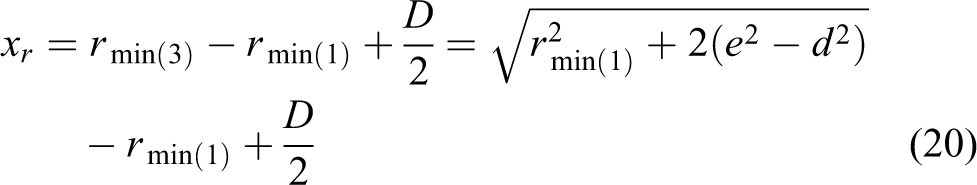
The minimum turning radius of the third segment is derived as

in which ψmax is the maximum longitudinal axis angle, and
And the turning radius of the first segment can be deduced as

The distance parameter xr can be given by

Case 2: d ≤ e
The turning radius of the segments from the first one to the last one increases in turn, while the longitudinal axis angle between the ith and the (i+1)th segments decreases in turn when the system run along an arc under the configuration of d ≤ e. The aforementioned relations can be explained as

The minimum turning radius of the first segment is derived as

in which ψmax is the maximum longitudinal axis angle, and
And the turning radius of the third segment can be deduced as

The distance parameter xr can be given by
Both cases of d ≥ e and d ≤ e should be comprehensively considered for the system. xr and xa are expressed as

Environmental models are obtained by enlarging obstacles when

Environment processing: (a) enlarging the obstacles by adopting the maximum extension size and (b) enlarging the obstacles by adopting ES. ES: equivalent size.
The improved A* algorithm is used to plan path for mobile articulated robots in free space. It can ensure itself as a collision-free and feasible path as long as the maximum path curvature is no larger than xa.
Path planning based on the improved A* algorithm
Environment modeling
Path planning mainly includes several steps: environment modeling, path searching, and path smoothing. Three common methods of environment modeling are grid method, geometric method, and topological graph. Grid method was proposed by Elfes 21 firstly. It has been widely applied, since it is easy to create and maintain. The overall environment is divided into several identically sized grids by adopting grid method, and then each grid should be indicated the presence of obstacles.
Mobile articulated robots system with three segments, recorded as ϒ, has shrunk to be a particle moving on two-dimensional plane. Several obstacles of the environment are mapped into hazardous areas that are refused to pass through. Δ is a convex polygon with limited and arbitrary shapes in the plane. There are several obstacles

Rasterizing environment of mobile articulated robots system with three segments.

The improved A* algorithm
The system moves safely and collision-free from an arbitrary initial node S to an arbitrary goal node T along an optimal path on Δ to complete the path planning. The A* algorithm integrates Dijkstra algorithm closed to the initial node with Breadth-First Search (BFS) algorithm closed to the goal node. The goal positional information of the system is considered. The A* algorithm starts from S and updates the weight of subnodes of the current node in sequence and the current node by the minimum of the weight of subnodes until all the nodes are traversed or the current node is the goal node. Grid map and 8-connected nodes expanding method are adopted. The Euclidean distance from the current node t to the goal node T is considered as the heuristic function for the mobile articulated robots system, that is

The initial planning path, recorded as Pi, is obtained by calculation. In the path planning process of the system, the minimum node of the evaluation function f(t) adopted as an expanding node is deposited into CLOSE(C) list until expanding to the goal node. The flow chart of path planning for mobile articulated robots system based on the A* algorithm is shown in Figure 6, in which t is a node has been planned; g(t) is the actual movement distance from S to t; h(t) is the heuristic function, that is, the heuristic distance from t to T; f(t) is the path evaluation function of t, and

Flow chart of path planning for mobile articulated robots system based on A* algorithm.
The improved A* algorithm is adopted to carry on the smoothing processing of the path to obtain the optimal planning path. All the nodes of the path are traversed based on the Pi. The path is extended and the middle node is deleted when there is no obstacle at the front and rear of the middle node, as illustrated in Figure 7, in which P* is the path planned by A* algorithm; SP* is the path planned by the improved A* algorithm;

Flow chart of path planning for mobile articulated robots system based on the improved A* algorithm.
Simulation results
The mobile articulated robots system with three segments moves in grid environments with obstacles distributed randomly. It is needed to verify the existence of obstacle between d and (d + 2) before connecting the two nodes. If it is yes, there is no passageway; otherwise it can be connected. It is easy to complete the path planning because the obstacles in the environment are arranged in neat array and the distance from the initial position to the goal position is short in Figure 8 and , while the obstacles with greater numbers in the environment are distributed randomly and the paths from the initial position to the goal position are more winding in Figure 8 and , in which the dotted line is the path planning obtained by the A* algorithm; the dashed line is the path planning obtained by the improved A* algorithm before the smoothing processing of corner; and the solid line is the path planning obtained by the improved A* algorithm after the smoothing processing of corner. The comparison of the planning paths between the A* algorithm (e.g. Figure 8 and ) and the improved A* algorithm (e.g. Figure 8 and ) shows that the quality of path by adopting the improved A* algorithm is superior to the A* algorithm no matter how complex the environment is.
There are a lot of problems in the planning path obtained by the A* algorithm as illustrated in Figure 8 and , such as many broken lines, turn times, and turn angles. The path is not what expected between the initial and goal positions in case of random distribution of obstacles.
The performance parameters of planning path obtained by the improved A* algorithm (e.g. Figure 8 and ) are superior to that of planning path obtained by the A* algorithm (e.g. Figure 8 and (c)) for mobile articulated robots system in case of random distribution of obstacles in a grid scale. For example, a 12.3% reduction in path length, a 25.3% reduction in accumulative turn times, and a 27.1% reduction in accumulative turn angles are obtained.
The improved A* algorithm makes the quality of path optimized and more suitable than the A* algorithm for path planning under the complex environment. The improved path meets the need of the optimal path planning for mobile articulated robots system seen from the above performance parameters.

Comparison of paths planning: (a) path planning obtained by the A* algorithm in the simple environment, (b) path planning obtained by the improved A* algorithm in simple environment, (c) path planning obtained by the A* algorithm in the relatively complex environment, and (d) path planning obtained by the improved A* algorithm in the relatively complex environment.
Conclusion
A path planning method for mobile articulated robots system composed of three segments connected by nonstandard form based on the improved A* algorithm is proposed. The trajectories of each segment are analyzed and the band path is described based on the kinematics model of the system firstly; secondly, ES is introduced to enlarge obstacles in the environment to shrink the system to be a particle and ensures that the planning path is collision-free and feasible; thirdly, the improved A* Algorithm is elaborated; finally, path planning by the A* algorithm and the improved A* algorithm in the simple environment and in the relatively complex environment are simulated in Matlab. From the reduction rates of the path length, the accumulative turn times, and the accumulative turn angles, the proposed path planning method for mobile articulated robots system is collision-free and feasible.
Future studies mainly focus on two tasks: enlarging the number of segments to N and establishing the kinematics model; enhancing the diversification of the environment and improving the precision of environmental model.
Footnotes
Declaration of conflicting interests
The author(s) declared no potential conflicts of interest with respect to the research, authorship, and/or publication of this article.
Funding
The author(s) received no financial support for the research, authorship, and/or publication of this article.