
Abstract
This article proposes two types of lockable spherical joints which can perform three different motion patters by locking or unlocking corresponding rotational axes. Based on the proposed lockable spherical joints, a general reconfigurable limb structure with two passive joints is designed with which the conceptual designs of two types of Exechon-like parallel kinematic machines are completed. To evaluate the stiffness of the proposed Exechon-like parallel kinematic machines, an expanded kinetostatic model is established by including the compliances of all joints and limb structures. The prediction accuracy of the expanded stiffness model is validated by numerical simulations. The comparative stiffness analyses prove that the Exe-Variant parallel kinematic machine claims competitive rigidity performance to the Exechon parallel kinematic machine. The present work can provide useful information for further investigations on structural enhancement, rigidity improvement, and dynamic analyses of other Exechon-like parallel kinematic machines.
Introduction
Parallel kinematic machines (PKMs) have been regarded as a promising alternative solution for the aeronautic and automotive industries due to their conceptual advantages of high rigidity and dynamics as well as good flexibility and reconfigurability. 1 Although hundreds of PKM structures have been proposed for various applications with their theoretical advantages, few of them have been successfully applied for real practices. 2 Publication tracking for the studies on PKMs reveals that the Tricept robot, 3,4 the Sprint Z3 Head, 5,6 and the Exechon machine tool 7,8 have been reported to achieve commercial success. By checking the structural arrangements of these “successful” examples, one may reflect the reasons that cause the gap between expected and actual performances of those “less successful” PKMs. It turns out that those “less successful” PKMs usually adopt parallel structure arrangements with too many passive joints. And these passive joints become new sources of geometric discrepancies and deformations when a PKM is subject to external loads or thermal loads.
Bearing with the thought of reducing the number of passive joints and unactuated degrees of freedom (DOF) of a PKM, Neumann
7
invented the Exechon PKM whose topological configuration is a 2U
Noticing that the topological configuration of the Exechon PKM (2U

Structure of two types of lockable spherical joints.
Unlike the extensively investigated Exechon PKM, 14 –19 the newly proposed Exe-Variant PKM requires systematically theoretical studies before it can be used for real practice. Among the theoretical studies, stiffness evaluation and enhancement are of great importance in that a PKM such as the Exe-Variant PKM designed for machining demands high rigidity and high dynamics. Therefore, a stiffness model needs to be established in priority to estimate the rigidity performance of the Exe-Variant PKM.
As to the stiffness modeling for PKMs, numerous investigations and efforts can be traced in the past decades. Among these investigations and efforts, finite element method (FEM), 20,21 matrix structure method (MSM), 22,23 screw-based method (SBM), 24,25 and semi-analytical method 26,27 are the most commonly used approaches. The authors recently established an efficient kinetostatic model for the Exechon PKM, with which the stiffness of an Exechon PKM module was estimated and the effects of design variables were discussed in a quick yet accurate manner. 28
Nevertheless, it needs to point out that the above kinetostatic model was specially established for the stiffness evaluation of the Exechon PKM and cannot be employed to the Exe-Variant PKM directly. Therefore, this article aims to expand our previous model to a general framework of stiffness modeling for the Exechon-like PKMs, such as the newly presented Exe-Variant PKM. For this purpose, the passive joints and the limb structures in an Exechon-like PKM are considered as compliant units whose compliances can be derived through analytical formulation and FEM simulation, respectively. On this basis, a general stiffness model for the Exechon-like PKMs is developed using the substructure synthesis technique.
With the proposed lockable spherical joints as well as the expanded general stiffness model, the stiffness performance of the Exe-Variant PKM can be estimated and compared with the Exechon PKM at a consistent parameters level.
The remainder of this article is organized as follows. In “Conceptual design of Exechon-like PKMs” section, the conceptual design for two kinds of lockable spherical joints is presented to construct an Exechon PKM and an Exe-Variant PKM followed by a brief definition for inverse kinematics. In “General stiffness modeling” section, a general kinetostatic model for the Exechon-like PKMs is established to derive an analytical expression of the governing stiffness matrix of the moving platform. In “Stiffness estimation and comparative analysis” section, the stiffness values of the Exe-Variant PKM are estimated and compared with the Exechon PKM. Finally, some conclusions and remarks are drawn in “conclusions” section.
Conceptual design of Exechon-like PKMs
In this section, two types of lockable spherical joints are firstly proposed. Based on the lockable spherical joints, a general reconfigurable limb structure is designed. With the reconfigurable limb structure, the conceptual designs of the Exechon PKM and the Exe-Variant PKM are developed.
Proposition of two types of lockable spherical joint
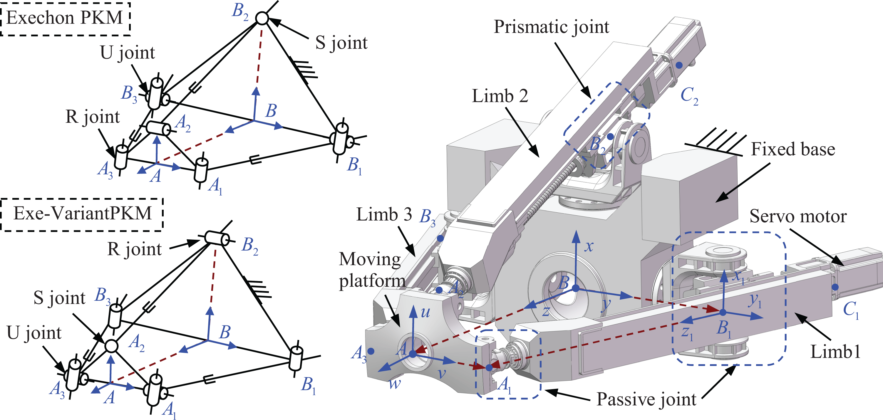
The conceptual design of two types of lockable spherical joints named as LSJ-I and LSJ-II is depicted in Figure 1. Such a lockable spherical joint possesses a unique structure consisting of sliding splines, external splined shafts, and internal splined hubs.
As shown in Figure 1, the sliding spline can move along the corresponding external splined shaft to connect or disconnect the internal splined hub. And two independent internal splined hubs are fixed to the joint body (LSJ-I and LSJ-II) and the limb (LSJ-I)/the base (LSJ-II), respectively. Under this circumstance, a rotation motion around the axis of external splined shaft can be automatically locked or unlocked, leading the lockable axis (the blue circle) to be a rotational axis or not. By locking or unlocking the two lockable rotation axes composed in Ai /Bi joint assembly, the above lockable spherical joint can undergo three motion patterns, that is, the revolute (R) joint, the universal (U) joint, and the spherical (S) joint.
As depicted in Figure 2, a lockable rotation axis is taken as an example to illustrate the working principle of the lockable spherical joint.
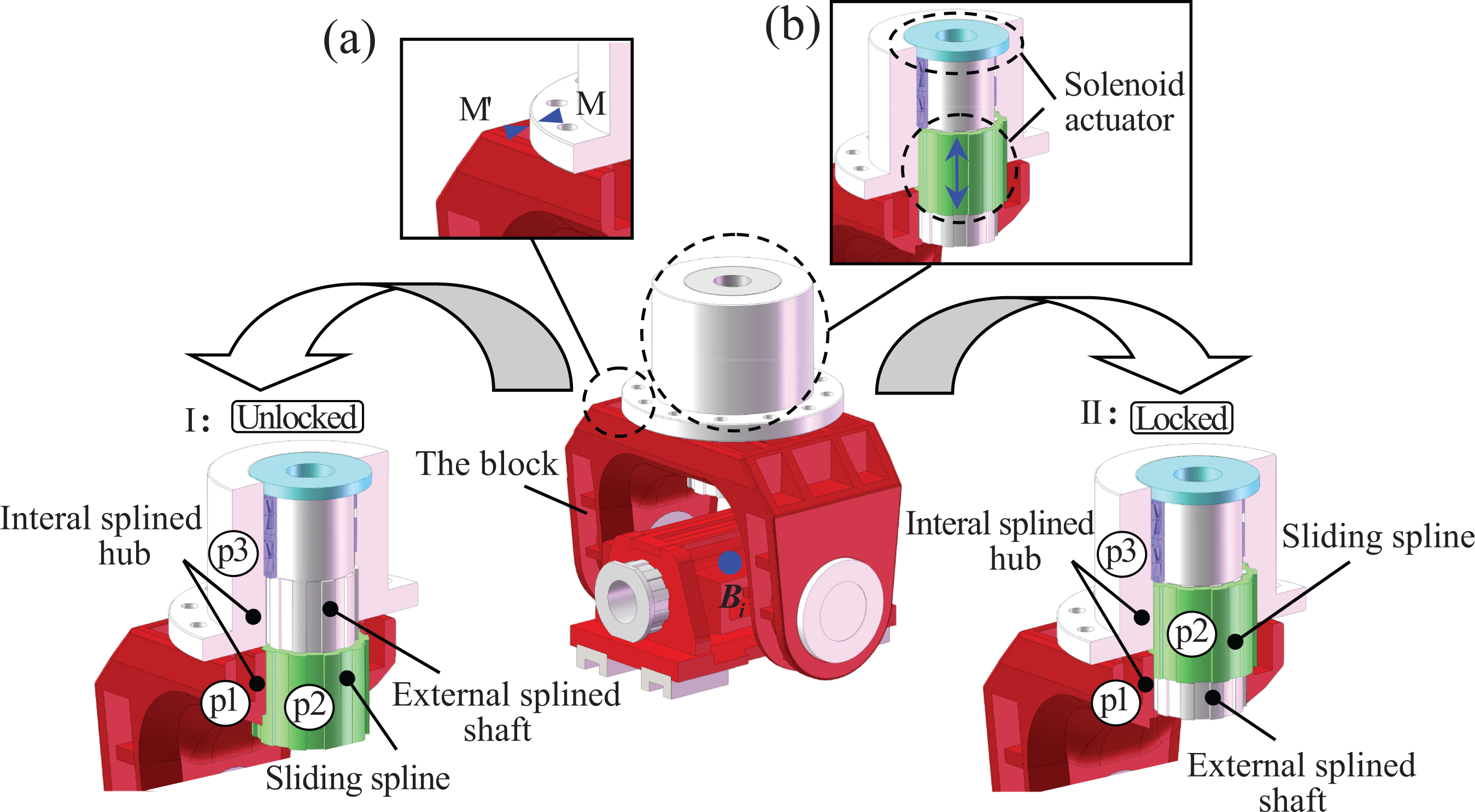
Working principle of the lockable rotation axis.
As can be observed in Figure 2, the lockable rotation axis mainly consists of a sliding spline, an external splined shaft, and two internal splined hubs connecting to the fixed base and the block, respectively. In order to achieve automatic driving and easy control, a solenoid actuator (Figure 2, part b) is adopted to shift the sliding spline. Furthermore, considering the clearance and misalignment existing in the spline assembly, two sensorimotor markers are assigned onto the fixed part and block (Figure 2, part a), respectively. The solenoid actuator can only be actuated when the two markers coincided accurately. Driven by the solenoid actuator, the sliding spline can move along the external splined shaft with two different positions, which provides the axis with two different configurations namely unlocked state and locked state. It is worthy to mention that the sliding spline can also be braked by the same solenoid actuator. Details are presented in the following.
Configuration I (unlocked state): The sliding spline p2 is moved downward to connect only with the internal splined hub p1 at the lower position. In this case, the sliding spline is still able to rotate with respect to the other internal splined hub p3. The motion around the external splined shaft is unlocked and the axis behaves as a rotational axis.
Configuration II (locked state): The sliding spline p2 is moved upward to connect both the internal splined hubs p1 and p3. In this case, the internal splined hub p1 cannot rotate about the external splined shaft, thus it behaves as a fixed axis.
LSJ-based reconfigurable limb
For the convenience of general performance comparing, the conceptual designs of Exechon and Exe-Variant PKM are achieved through a general reconfigurable limb structure containing two types of the newly proposed lockable spherical joint.
As shown in Figure 3, the general limb structure consists of two passive joints assembly Ai
and Bi
(i = 1, 2, 3) located in the fore part and the upper part of the limb body, respectively. Herein, we denote the vector

Design of a general reconfigurable limb.
Based on the above conceptual design, one may achieve a revolute joint and universal joint when corresponding lockable rotational axes are locked in Ai /Bi joint assembly, respectively, while there is no rotation axis needed to be locked in a spherical joint. The detailed assignments are shown in Table 1.
Locked rotational axes in corresponding joints.

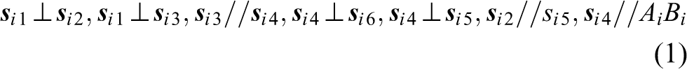
Two types of overconstrained Exechon-like PKM
As is well known, the topological architecture behind the Exechon PKM is a 2U
Conceptual design of two types of Exechon-like PKMs. (a) The Exechon PKM and (b) The Exe-Variant PKM. PKM: parallel kinematic machine.
Following a similar track, a conceptual design of the Exe-Variant PKM can be achieved and presented in Figure 4(b), whose topological architecture is a 2R
Added with a 2-DOF rotational manipulator or a 2-DOF translation slider, the proposed two types of Exechon-like PKMs can be constructed as a 5-axis machining center, which can be employed to perform high-speed machining such as milling, drilling, riveting, and polishing for large-scale aluminum alloy structural components with complex geometries or to perform forced assembling in automotive industry. It is expected that the two types of PKMs can be used as an alternative solution for the Exechon machine or the Tricept robot.
Kinematic definitions for the two types of overconstrained Exechon-like PKMs
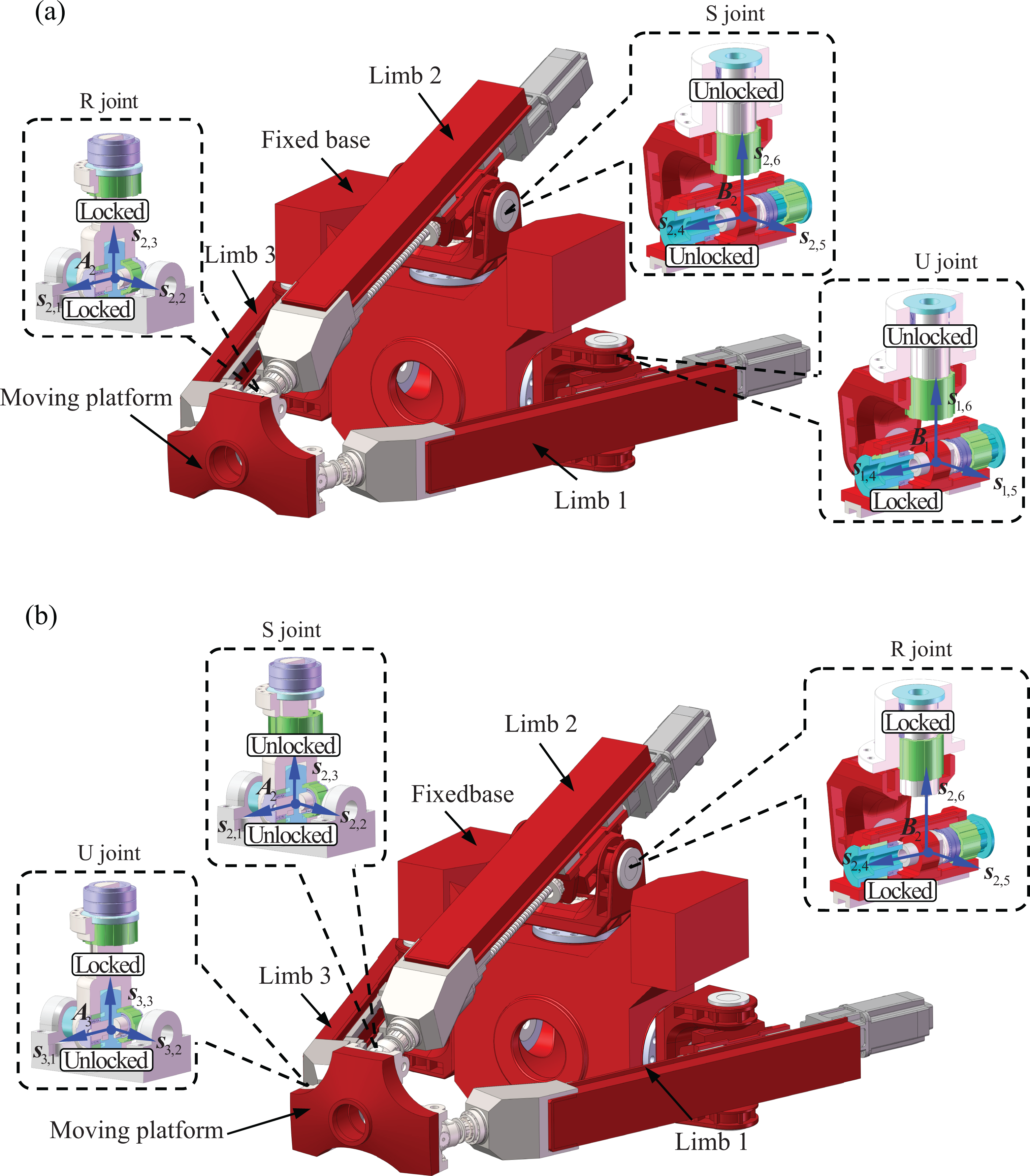
For the convenience of stiffness modeling and comparison, some basic kinematic definitions need to be made in priority. The schematic diagram of a general Exechon-like PKM is depicted in Figure 5.
Schematic diagram of a general Exechon-like PKM. PKM: parallel kinematic machine.
As shown in Figure 5, a global Cartesian coordinate system B-xyz is fixed at the middle point of B 1 B 3, with x-axis coincident with BB 2, y-axis coincident with BB 1, while z-axis is determined by the right-hand rule. Similarly, a body-fixed Cartesian coordinate system A-uvw is assigned to the moving platform, with u-axis coincident with AA 2, v-axis coincident with AA 1, respectively, while w is determined by the right-hand rule. Meanwhile, a limb reference coordinate frame Bi -xiyizi (i = 1, 2, 3) is established at the center of the ith passive joint Bi with xi parallel to x-axis, zi preferred to be projecting from Bi to Ai , while yi is determined by the right-hand rule. For clarity, only one limb reference frame in limb 1 is depicted in Figure 5.
With the above coordinate settings, one may derive the transformation matrix between the body-fixed frames and the global coordinate system using the knowledge of kinematics.
Assume that the transformation matrix of A-uvw with respect to B-xyz is
B

Similarly, one may denote the transformation matrix of Bi -xiyizi with respect to B-xyz as

Taking the Exechon and the Exe-Variant PKMs as examples, their detailed inverse kinematic analyses can be referred to the studies by Tang et al. and Zhang et al., 9,28 respectively.
General stiffness modeling
The proposed two types of Exechon-like PKMs are designed for high-speed machining and forced assembling, in which high rigidity and high positioning accuracy are required. Therefore, the stiffness performance of such kinds of PKMs becomes the most overwhelming concern in their design stage. To reveal the rigidity characteristics of the two types of PKMs, a stiffness model as well as the stiffness analysis must be carried out.
In order to formulate a general stiffness expression for the Exechon-like PKMs, an expanded kinetostatic model is proposed using the technique of substructure synthesis. The purpose of the general stiffness modeling is to derive an analytical global stiffness matrix for the Exechon-like PKMs with prismatic actuators, from which a 6 × 6 stiffness matrix can be extracted to estimate the rigidity performance of the PKM’s platform.
Assumptions
To facilitate the establishment of general stiffness model for the Exechon-like PKMs, the following hypotheses and approximations are made according to the structural features of the PKMs. The fixed base and the moving platform are treated as rigid bodies due to their comparatively higher rigidities. The passive joints and the prismatic actuator assemblages are regarded as flexible components. The flexibilities of these compliant components are represented by 6-DOF virtual lumped springs with equivalent stiffness coefficients located at their geometric centers. The limb structure is considered as a deformable body having bending, extension, and torsion deflections when subject to the reactions from passive joints. The deformations of the limb body can be calculated through finite element (FE) formulation by modeling the limb as a spatial beam with corresponding cross-section constrained by passive joints according to its structural features. The frictions, dampings, and dynamic effects are neglected during the kinetostatic modeling process. However, they can be incorporated into the system governing equations with further efforts.
Static equations of the subsystems
The force diagram of an individual limb assembly in an Exechon-like PKM is shown in Figure 6. Herein, Ai and Bi represent the geometric centers of the two passive joints connected to moving platform and fixed base, respectively; Ci denotes the rear end of a limb body where the servomotor is installed.

Force diagram of an individual limb assembly.
As aforementioned, the two passive joints are simplifying as two sets of virtual springs with equivalent stiffness coefficients. Thus, an individual limb assembly can be regarded as a spatial beam constrained by two sets of lumped springs. Such a spatial beam can further be meshed into FEs with each node having three linear and three angular coordinates along/about three perpendicular axes, respectively. 29 Assume that the ith limb body is divided into n elements with Ai , Bi , and Ci being the first, the (j + 1)th and the (n + 1)th nodes, respectively. For clarity, ei 1, ei 2,…, ei (n+1) denote the element nodes in the discrete spatial beam which define a set of local reference frame eij -xijyijzij at the element eij with its three axes parallel to those in the limb frame Bi -xiyizi in sequence.
By considering the boundary conditions aroused from the passive joints, a set of static equilibrium equations for the ith limb in the frame of Bi -xiyizi can be formulated as

where
The general coordinates

where
The general load vector

where


where
The above equivalent spring constants can be determined either by FE computation or by semi-analytical regression according to the assembly relationships and structure features of the passive joints. The elastic deformations of the passive joints can also be derived through the compatibility conditions between the limb structure and the moving platform (or the fixed base) as shown in Figure 7.
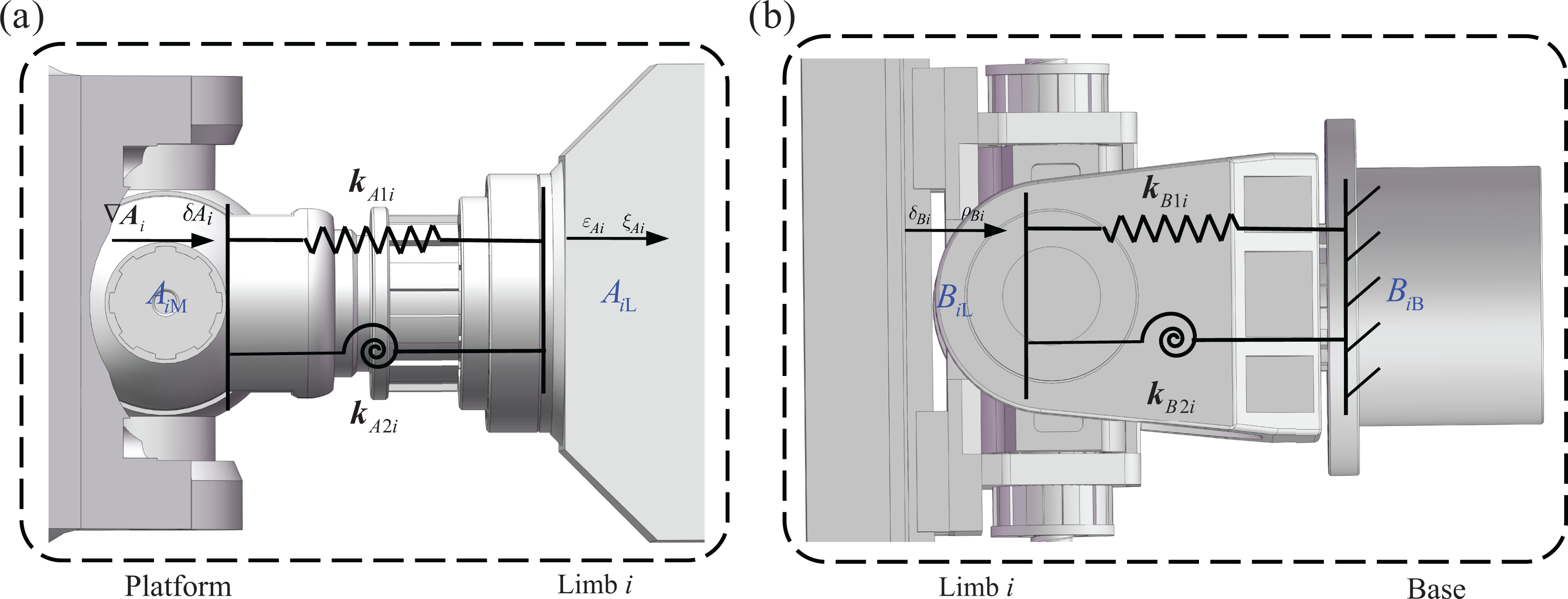
Two types of compatibility conditions.
Figure 7(a) demonstrates the compatibility condition between the moving platform and the limb structure. Herein, the passive joint is simplified as a virtual lumped spring with equivalent linear stiffness

where

where 
Herein,
In equations (10) and (11), the transformation matrices of

where
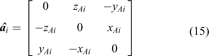
where xAi , yAi , and zAi are the coordinates of point Ai measured in the global frame B-xyz.
Similarly, the second deformation compatibility condition defining the displacement relationship between the fixed base and the ith limb can be demonstrated as Figure 7(b). Herein, Bi
B and Bi
L denote the interface points associated with the fixed base and the ith limb, respectively.

where

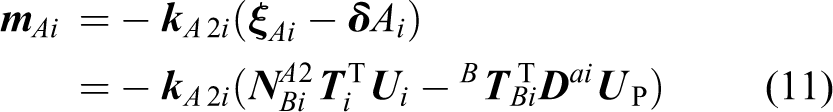
As a result, the reactions from passive joint Bi can be formulated as

Equation (4) can be further expressed in the global coordinate system B-xyz as

where

The force diagram of the moving platform is shown in Figure 8.

Force diagram of the moving platform.
In Figure 8,

Based on the Newton’s second law, the static equations of the moving platform can be formulated as the follows


where
Stiffness formulation of the moving platform
Assembling the static equations of the subsystems of the limbs and the moving platform, one can obtain the governing equilibrium equations of an Exechon-like PKM as

where


The global stiffness matrix can be expanded in details as
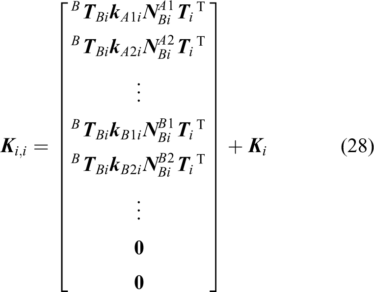


Equation (27) formulates the global stiffness matrix of the Exechon-like PKM which indicates that the stiffness of the moving platform is coupled with those of the limb structures. Therefore, the concept of compliance is adopted to evaluate the rigidity of the moving platform, which can be mathematically expressed as

With equation (32), the compliance matrix of the moving platform can be obtained from the last 6 × 6 block matrix in 
Stiffness estimation and comparative analysis
Without loss of generality, the Exechon and the Exe-Variant PKM shown in Figure 4 are taken as examples to demonstrate the versatility of the proposed general stiffness methodology.
Parameters of the example systems
For the convenience of rigid performance comparison, the major parameters of the two example systems are taken at the same geometrical level and are listed in Table 2. Herein, r a and r b denote the radii of the moving platform and fixed base; s denotes the stroke of the moving platform along z-axis; d min and d max represent the minimum and the maximum distances between Ai and Bi ; and ψ max and θ max denote the maximum precession angle and the maximum nutation angle, respectively.
The dimensional parameters of the two example systems.

Meanwhile, the equivalent spring constants of the passive joints along and about the three directions are listed in Tables 3 and 4. These spring constants are determined through FE simulation from ANSYS WorkbenchTM [Version 15.0] according to the joint structure.
The equivalent spring constants of the Exechon PKM.

PKM: parallel kinematic machine.
The equivalent spring constants of the Exe-Variant PKM.

PKM: parallel kinematic machine.
With the above parameters, the following stiffness analyses can be carried out.
Stiffness analysis at a given typical configuration
By solving equation (33), one can obtain the stiffness values of the moving platform at any configurations within its workspace. For the sake of clarity, the diagonal elements in the matrix
Without loss of generality, a typical configuration (z = 1120 mm, θ = 0°, ψ = 0°) is taken as an example to demonstrate the stiffness evaluation. The obtained stiffness matrices of the moving platform for the Exechon PKM
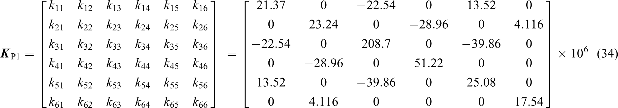

where k 11, k 22, and k 33 denote the linear principle stiffness values along u-, v-, and w-axes, respectively; k 44, k 55, and k 66 represent the angular principle stiffness values about u-, v-, and w-axes, respectively. The other elements in the above equations are the coupled stiffness values.
From the above equations, it can be clearly found that the linear principle stiffness values along u- and v-axes are much less than that along w-axis for both the Exechon and the Exe-Variant PKMs. This implies that the two types of PKM claim the highest rigidity along the w direction, while the rigidities along the other two directions are comparatively “soft.” Thus, the two bending stiffness of the moving platform must be paid enough attentions during the design stage. On the contrary, the angular principle stiffness values about u- and v-axes are much higher than that about w-axis, indicating a “weakest” rigidity about the w direction of the moving platform. Furthermore, by comparing equations (34) and (35), one may conclude that the Exe-Variant PKM claims a comparative rigidity performance to the Exechon PKM in that they share the same magnitude levels for the principle stiffness values in the same directions.
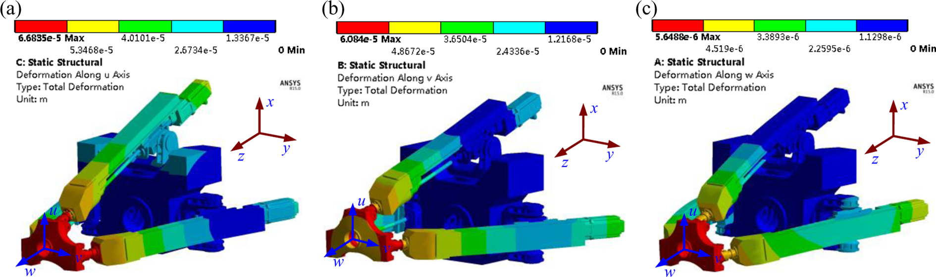
To validate the accuracy of the proposed stiffness model, a numerical model for the two types of PKMs is developed in ANSYS Workbench™ [Version 15.0]. When the two example systems locate at the typical configuration of z = 1120 mm, θ = 0°, ψ = 0°, a 1000 N force is applied at the center of the platform along u-, v-, and w-axes, respectively, to conduct a static analysis. The corresponding deformations of the two example systems are demonstrated in Figures 9 and 10, respectively.

Deformations of the Exechon PKM: (a) in u direction, (b) in v direction, and (c) in w direction. PKM: parallel kinematic machine.
Deformations of the Exe-Variant PKM: (a) in u direction, (b) in v direction, and (c) in w direction. PKM: parallel kinematic machine.
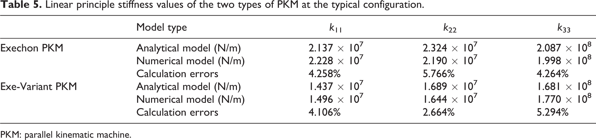
With force–displacement relationships along the three perpendicular directions, the linear principle stiffness values of the two types of PKM can be calculated and then compared with the analytical results obtained from the above stiffness model. The detailed data are listed in Table 5.
Linear principle stiffness values of the two types of PKM at the typical configuration.
PKM: parallel kinematic machine.
From Table 5, it can be clearly observed that the calculation errors between the analytical results and the numerical simulations are very close, with the largest error less than 6%. This indicates that the proposed general model can predict the stiffness of the Exechon-like PKM accurately, thus can be used for rigidity performance evaluation throughout the workspace in the following part.
Stiffness evaluation over a given work plane
The following will illustrate the mappings of the six principle stiffness values of the Exechon-like PKMs over the work plane of z = 1120 mm. The results are depicted in Figure 11.

Stiffness mappings of the Exechon-like PKMs (red for the Exechon, blue for the Exe-Variant). PKM: parallel kinematic machine.
From Figure 11, it can be observed that the stiffness mappings of the two PKMs are strongly position dependent. To be more specific, the stiffness values are axisymmetrically distributed over the given work plane due to the symmetric structural features of the PKMs, that is, limb 1 and limb 3 are symmetrical with respect to limb 2.
Further observations of the mapping of k 11 reveal that the Exe-Variant PKM possesses a higher rigidity performance than the Exechon PKM along u direction when the nutation angle of the moving platform exceeds an interval of [−18, 8]°. Similarly, from the mapping of k 22, it can be found that the Exe-Variant PKM possesses a higher rigidity performance than the Exechon PKM along v direction when the precession angle of the moving platform exceeds an interval of [−10, 10]°. This may indicate that the proposed Exe-Variant can achieve better rigidity performance when the moving platform works near the boundary of workspace, while the Exechon possesses higher stiffness when the moving platform is parallel to the fixed base.
As to the mapping of k 33 for the two types of PKMs, it can be found that the Exechon PKM possesses better rigidity performance over the entire work plane. It is very interesting that the mappings of k 44 and k 55 demonstrate an “inverse” distribution effect. To be more specific, the angular principle stiffness values about u direction of the Exechon PKM are larger than those of the Exe-Variant except for a very small region near the work plane boundary, while the angular principle stiffness values about v direction of the Exe-Variant PKM are larger than those of the Exechon except for a very small region near the work plane boundary. When it comes to the distribution of k 66, it can be seen from the above figure that the Exechon PKM is more rigid than the Exe-Variant when the platform works in the “center part” of the work plane. However, when the platform reaches the workspace boundary, it can be expected that the Exe-Variant possesses more desirable rigidity performance than the Exechon PKM.
Conclusions
To summarize the contributions of this article, the following conclusions can be drawn: Two types of lockable spherical joints are firstly proposed and designed. The proposed lockable spherical joints can achieve three motion patterns including the revolute (R) joint, the universal (U) joint, and the spherical (S) joint. Based on the two lockable spherical joints, a general reconfigurable limb structure is designed with which the conceptual designs for an Exechon and an Exe-Variant machine are completed. An expanded general kinetostatic model is established to evaluate the stiffness of the Exechon-like PKMs. The accuracy of the proposed stiffness model is validated by numerical simulations. Thus, the proposed methodology can be applied to estimate the rigidity performance of the Exechon-like machines as well as other kinds of overconstrained PKMs. The comparative stiffness analyses prove that the proposed Exe-Variant PKM has a competitive rigidity performance to the Exechon PKM, especially when the moving platform reaches the workspace boundary. The presented lockable spherical joints can be regarded as a promising solution for the design of reconfigurable overconstrained PKMs with passive joints. It is also worthy pointing out that the conceptual design for the two types of Exechon-like PKMs still remains for improvement. Further investigations including prototype fabrication, stiffness testing, and other performance validations will be our next work.
Footnotes
Declaration of conflicting interests
The author(s) declared no potential conflicts of interest with respect to the research, authorship, and/or publication of this article.
Funding
The author(s) disclosed receipt of the following financial support for the research, authorship, and/or publication of this article: This work was supported by the Open Fund of the State Key Laboratory for Manufacturing Systems Engineering (Xi’an Jiaotong University) with grant no. sklms2015004 and Open Fund of Shanghai Key Laboratory of Digital Manufacture for Thin-walled Structures with grant no. 2014001. The first author would like to acknowledge for Innovation Research Fund for Postgraduates of Anhui University of Technology (grant no. 2015032).