
Abstract
Aiming at vision applications of our amphibious spherical robot, a real-time detection and tracking system adopting Gaussian background model and compressive tracking algorithm was designed and implemented in this article. Considering the narrow load space, the limited power resource and the specialized application scenarios of the robot, a heterogeneous computing architecture combining advanced Reduced Instruction-Set Computer (RISC) machine and field programmable gate array was proposed on the basis of Zynq-7000 system on chip.Under the architecture, main parts of the vision algorithms were implemented as software programs running on the advanced RISC machine-Linux subsystem. And customized image accelerators were deployed on the field programmable gate array subsystem to speed up the time-consuming processes of visual algorithms. Moreover, dynamic reconfiguration was used to switch accelerators online for reducing resource consumption and improving system adaptability. The word length of accelerators was optimized with simulated annealing algorithm to make a compromise between calculation accuracy and resource consumption. Experimental results confirmed the feasibility of the proposed architecture. The single board tracking system was able to provide an image processing rate of up to 89.2 frames per second at the resolution of 320 × 240, which could meet future demands of our robot in biological monitoring and multi-target tracking.
Keywords
Introduction
Visual tracking is an active research topic in the field of computer vision with robotic applications ranging from visual servoing, automatic navigation and robot–human interaction. Given the initial state (e.g., position and scale) of a specific target in the first frame of a video or an image sequence, a visual tracker seeks to estimate the states of the target in the subsequent frames. Some state-of-the-art tracking algorithms including tracking–learning–detection (TLD), 1 multiple instance learning (MIL), 2 structured output tracking with kernels (STUCK) 3 and L1 tracker using accelerated proximal gradient (L1APG) 4 have been proposed in recent years. Although numerous tracking algorithms have been proposed, 5 it still remains a very challenging task to design a low-power real-time tracking system for mobile robotic applications. 6 –8 On the one hand, most embedded processors for mobile robotic applications have a relatively weaker computational ability compared with multicore central processing unit (CPU) in workstations, which leads to difficulties for real-time image processing. On the other hand, visual tracking algorithms have to process images successively, which covers processes of image preprocessing, appearance modelling, motion estimating, target locating and model updating. 5 Consequently, it results in a great number of compute-extensive operations.
Aiming at exploration tasks in littoral regions, a small-scale amphibious spherical robot was proposed by our team in 2012. 9 Given the characteristics of the robot and the amphibious environments, a camera is important for it in executing observation and investigation tasks autonomously. 10,11 Focusing on vision applications of our amphibious spherical robot, a low-power real-time detection and tracking system was designed and implemented in this article. Gaussian background model was adopted to detect moving target entering the field of view. Then, compressive tracking (CT) algorithm was used to track the detected target successively. 6 Given the limited load space and potential application functions of the robot, a novel architecture of heterogeneous computing systems combining advanced Reduced Instruction-Set Computer (RISC) machine (ARM) and field programmable gate array (FPGA) was proposed on the basis of Xilinx Zynq-7000 SoC (system on chip) to implement the detection and tracking system. Under the proposed architecture, the main part of vision algorithms was running on the ARM-Linux embedded subsystem as software. And customized image accelerators designed with high-level synthesis (HLS) tools were deployed on the FPGA subsystem to speed up compute-intensive processes of vision algorithms. Moreover, dynamic reconfiguration was used to switch accelerators running on the programmable logic (PL), which reduced consumption of FPGA resources and provided an extendable acceleration mechanism for embedded image processing. Besides, the word length of image accelerators was optimized with simulated annealing algorithm to make a compromise between numerical calculation accuracy and resource consumption of the PL. Various experiments were conducted to verify the validation of the proposed heterogeneous architecture and the practicality of the tracking system. Test results indicated that the system was able to provide a detection rate of up to 88.3 frames per second (fps) and a tracking rate of up to 89.2 fps at the resolution of 320 × 240, which could meet the application requirements of our robot. Its good real-time performance could also meet future demands of the robot in biological monitoring and multi-robot collaboration.
The rest of the article is organized as follows. An overview on our amphibious spherical robot and existing low-power real-time visual tracking solutions is provided in the section ‘Related works and application requirements’. CT algorithm is analysed and evaluated in the section ‘Analysis and evaluation on compressive tracking algorithm’. Design details of the proposed detection and tracking system are elaborated in the section ‘Zynq-7000 SoC-based low-power real-time tracking system’. Optimization design of the system including word length optimization and dynamical reconfiguration is described in the section ‘Optimization design of the proposed visual tracking system’. Experiments and evaluations on the proposed system are conducted in the section ‘Experimental results and discussions’. Section ‘Conclusions’ describes conclusions and follow-up research works. An appendix with the principles of the CT algorithm and the Gaussian background model is also included.
Related works and application requirements
Amphibious spherical robots
As shown in Figure 1, the amphibious spherical robot consisted of a waterproof hemispheric upper hull (diameter: 250 mm), in which electronic devices and scientific instruments were installed, and two openable quarter-sphere lower shells (diameter: 266 mm). In the land mode, the robot walked with four legs. In the underwater mode, it swam with water jets. In 2014, an improved version of the amphibious spherical robot was proposed using 3D printing technology and adding sensors including gyroscopes, accelerometer, global position system and cameras. 12 Different from most existing mobile robots or autonomous underwater vehicles, the robot was able to work in complex and narrow environments like coral reefs and pipelines. 13,14

Diagram of the amphibious spherical robot.
Due to the unique mechanical structure and the specialized application scenarios, designing a tracking system for our amphibious spherical robot was a challenging task. First, the load space of the robot was very narrow and was designed as enclosed for waterproofing. Thus, a high-speed computer or workstation, which is usually in large size and generates a great deal of heat, was not suitable for this small-scale mobile robot. Second, the robot was powered by lithium batteries, the total capacity of which was 4800 mAh. So the power consumption of its robotic vision system shall be considered to ensure enough work range. Third, future applications of the robot include biological monitoring and multi-robot collaboration. The robotic vision system may need to track multiple targets or a high-speed target like fish. Therefore, the real-time performance of the tracking system shall be especially considered. Besides, precision and effectiveness of the adopted tracking algorithm should be acceptable to meet the requirements of robotic applications like visual servoing. To address issues mentioned above, a low-power real-time tracking system build upon embedded processors was essential for applications of our amphibious spherical robot.
In 2015, a prototype moving target detection system was constructed for the robot using an SoC. 12 The Gaussian background model was used for foreground detection and a customized accelerator was designed to ensure real-time image processing. However, the framework of the prototype system was coarse and inefficient, which resulted in a high CPU workload and a slow response speed of the robotic control system. Besides, the adopted power optimization methods were not effective enough, which limited its applications in practical scenarios.
Low-power real-time visual tracking systems
To overcome the high-computing load problem, the mainstream solution of real-time visual tracking systems is implementing algorithms with graphic processor units (GPUs), 15 digital signal processors (DSPs), 16 FPGAs 17 or application-specific integrated circuits (ASICs). 18 However, tracking systems built upon a single specific purpose processor or PL device have drawbacks in real-time performance, developing difficulties, cost and extendability, respectively. That limited their applications in battery-powered or multiple functional platforms like autonomous mobile robots.
Hybrid or heterogeneous systems integrated advantages of multiple solutions and have been widely used in real-time vision applications in recent years. In general, CPU–GPU is the most popular hybrid solution in the field of computer vision for its excellent performance. 19 However, most CPU–GPU heterogeneous systems are fabricated as computers or workstations, which have high power consumption and are not suitable for small-scale mobile robots. Moreover, programs of vision algorithm shall be carefully optimized to use CPU and GPU simultaneously for a high utilization rate. Besides, the program portability problem between some types of NVIDIA GPUs still exists.
Another widely used hybrid solution for visual tracking is DSP–FPGA which attaches customized hardware (i.e., FPGA) to an easy-to-develop processor (i.e., DSP). Tomasi et al. 20 designed a sparse optical flow-based smart video sensor using FPGA and DSP co-processing architecture. Harris corner detection algorithm was implemented on the FPGA, and the DSP tracked the target using features detected by the FPGA. An overall frame rate of 160 fps for 640 × 480 resolution was finally achieved on this hybrid system. Wang et al. 21 designed a correlation tracking system using Texas Instruments TMS320DM642 DSP and Xilinx Spartan-3E FPGA, and a frame rate of 25 Hz for 720 × 576 resolution was achieved. For a better multitasking capability and software portability, heterogeneous computing systems centred on general-purpose (GP) processors, such as ARMs, were also used in some studies. 22 In an ARM–DSP hybrid system, a DSP usually served as the specified image accelerator, which executed time-consuming image processing operations and lightened the burden of an ARM processor. 23 But most hybrid systems mentioned above used an external interface to connect the two devices. A low-efficient and low-reliable interface turned into the performance bottleneck of these systems, which may cause low utilization rate of the accelerator and poor real-time performance. 19 Besides, reliability, power consumption and size of these systems should also be considered in some application scenarios.
A hybrid system containing two processors on a single chip, commonly known as SoC, has recently become a booming trend in embedded systems for image processing. 24 Because a SoC combines a GP processor with a PL device together seamlessly, it provides flexibility and extendibility beyond conventional solutions. Zhou et al. 25 proposed a novel inertial-assisted visual odometry system intended for low-cost micro-aerial vehicles. A low-cost Altera SoC FPGA with a 600 MHz ARM Cortex processor inside was adopted as the system core. A features from accelerated segment test (FAST) feature detector and a binary robust independent elementary features (BRIEF) descriptor were realized on the FPGA to assist real-time tracking. Gao et al. 26 proposed a real-time embedded video target tracking system for real-world airborne video with a Texas Instruments, US, OMAP 3730 ‘ARM + DSP’ embedded processor. The DSP core was utilized as a motion estimation preprocessing unit, and the ARM core worked for further processing. Compared with dual-processor hybrid systems, SoC-based systems have advantages of compact size, low-power consumption and extendability. However, numerous configurations on low-level hardware shall be dealt to launch these systems normally. And most customized accelerators running on FPGA shall be developed with hardware description languages (HDLs), which are not suitable for developing complex numerical functions. These characteristics resulted in great difficulties to deploy subtle visual algorithms. Consequently, most state-of-the-art tracking algorithms were not implemented on embedded systems or used in practical applications yet.
In 2010, Xilinx Inc. launched an all-programmable SoC named Zynq-7000. Unlike most existing SoC FPGA containing dedicated processor hardware cores, Zynq is formed around an application grade processing system (PS), which consists of an ARM Cortex-A9 dual-core processor and essential hardware peripherals for running full operating systems such as Linux. The PL, which is equivalent to a Xilinx 7-series FPGA, served as a programmable peripheral of the PS. The PS is able to multitask complex works, and the PL is suitable to implement digital interfaces or parallel arithmetic units.
Moreover, high-speed Advanced eXtendable Interface (AXI) buses provide low latency data exchange channels between the two sections, which makes it efficient to transfer partially processed data inside the heterogeneous system. AXI ports connecting the PS and the PL, including four GP ports, four high-performance (HP) ports and an accelerator coherency port (ACP), provide a data transfer rate of up to 8 GBps. According to different characteristics of these AXI ports, they can be used to connect different instantiating intellectual property (IP) cores for various applications. As shown in Figure 2, the PS usually accesses configuration registers of peripherals on the PL through AXI-GP ports in low-speed applications such as motor control. AXI-HP ports are suitable for high-speed applications in which an IP core needs to access the double data rate (DDR) random access memory (RAM), for example, video stream processing or image acquisition. Because the AXI-ACP port is able to access the DDR and supports coherency with the CPU cache, it can be used for applications needing a shared work spaces between the software and the hardware, such as interactive image processing.

Diagram of Zynq-7000 SoC-based use cases. 27 Red arrow lines indicate data-path of AXI-GP ports. Green arrow lines indicate data-path of AXI-HP ports. Purple arrow lines indicate data-path of the AXI-ACP port.
Zynq combines advantages of ARM and FPGA and overcomes the communication problem between the two sections. Thus, it provides a feasible solution for control and processing systems of small-scale autonomous mobile robots. 28 However, as far as we know, few studies were made to fully tap its potential in robotic vision. Focusing on the application problem of the amphibious spherical robot, a Zynq-7000 SoC was used to construct the robotic tracking system in this article. A sophisticated heterogeneous computing system architecture, which took full advantages of its characteristics, was proposed to ensure the real-time performance of the vision system. Moreover, optimization methods including dynamic reconfiguration and word length optimization were designed to further reduce the power consumption and to enhance the system flexibility.
Analysis and evaluation on CT algorithm
In 2012, Zhang et al. 6 proposed the CT algorithm, which provided a concise and efficient solution for real-time visual tracking applications. The primary innovation of the CT algorithm was the compressive sensing-based random feature extraction method. Benefiting from this fast and effective way to compress raw pixel data, the CT algorithm succeeded in excellent real-time performance. 29 Meanwhile, the online learning Naïve Bayes classifier used for separating the target from background, which is a simple but effective pattern recognition method, ensured the tracking robustness to disturbances like appearance changes, camera vibration, and so on. 30 Because the CT algorithm found a balance point between the real-time performance and effectiveness, it has a bright future in low-power real-time computer vision applications.
However, as far as we know, most CT-based tracking systems were running on personal computers (PCs) or workstations. 31 Because the computational consumption of the CT algorithm is still too large for most embedded platforms, there were no related application cases of mobile robots.
For an accurate evaluation towards the computational consumption of the CT algorithm, we rewrote the program on eclipse with C language using no dependent libraries like OpenCV. The algorithm program ran on a PC (Intel Core i7-4712MQ, 8 GB DDR3 RAM, Windows 7 64-bit) and a Zynq embedded system (ARM Cortex-A9 Dual-core 667 MHz, 512 MB DDR3 RAM, Linux 3.2.16), respectively. The time consumption data of the CT algorithm at different resolutions was as shown in Table 1. Because the CT algorithm adopted the random Haar-like feature model and the dimension of feature vectors to be processed by the classifier was static, the real-time performance of CT has little relationship with the image resolution. Without program optimization, the processes of integral image calculation, compressive sensing and Naïve Bayesian classifier cost 20.4%, 11.9% and 64.7% of the whole time when running on the computer, respectively. The corresponding percentages when running on the ARM were 17.8%, 18.2% and 60.0%, respectively. The process of compressive sensing contains a great amount of floating-point multiplication and add operations. The Naïve Bayesian classifier mainly involves exponent and logarithm operations, which are equivalent to floating-point multiplication operations according to Taylor series. The pure software solution on ARM could only provide a processing rate of 6.0 fps on average, which could not meet the requirements of robotic applications. Hence, hardware accelerating measures shall be taken on these time-consuming processes to ensure real-time performance.
Computational consumption analysis of CT algorithm.

CT: compressive tracking; fps: frames per second; PC: personal computer; ARM: advanced RISC machine.
Zynq-7000 SoC-based low-power real-time tracking system
Heterogeneous architecture of the real-time tracking system
The heterogeneous computing architecture of the low-power real-time tracking system proposed in this article was as shown in Figure 3. The major parts of software and digital hardware of this system were integrated on a single Xilinx Zynq-7000 SoC. The software concerning system control and serial processes of algorithms was running on the PS which provided an embedded Linux environment. The hardware, including the image acquisition logic, the customized image accelerator logic and other digital interfaces or logics, was deployed on the PL.

Diagram of the Zynq-7000 SoC-based low-power real-time tracking system. Green arrow lines indicate AXI-Lite buses. Blue arrow lines indicate AXI-Stream buses. Blocks marked in blue indicate programmable modules deployed on the PL. The block marked in yellow indicates a reconfigurable module deployed on the PL.
The image acquisition logic was composed of a camera interface module controlling the camera, an AXI-DMA module transferring acquired images to the DDR3 RAM through an AXI-HP port and an image preprocess module completing image enhancement operations. The customized image accelerator logic was centred on a reconfigurable image accelerator, which is an FPGA-based digital circuit executing specific time-consuming operations of image processing algorithms. The image accelerator can be reprogrammed online by the PS through the processor configuration access port (PCAP). Two AXI-DMA modules were used to realize bidirectional data transfer between the accelerator and the DDR3 RAM through the AXI-ACP port.
Data exchange between the IP cores was completed through AXI4-Stream buses. The PS controlled the work mode of these IP cores by accessing control register banks via AXI-GP ports. The AXI ports used for DMA transfers of the image acquisition and the image accelerator were separated to avoid bandwidth competition. Considering that the data exchange or interactive operations between the software and the accelerator may be frequent, the AXI-ACP port was assigned to connecting the customized image accelerator logic.
In our system, an OV7670 COMS camera was adopted and configured to capture 320 × 240 16-bit RGB images at 30 fps. In the image preprocess module, acquired colour images were converted into 320 × 240 8-bit grey images and were then transferred to the DDR3 RAM. The whole working process of the system was divided into two stages: the detection stage and the tracking stage. In the detection stage, the Gaussian background model-based detection program was running on the PS to sense moving object entering the field of view. And the accelerator of Gaussian background model was programmed to the reconfigurable area of the PL. The detector would mark the target to be tracked once it found an eligible moving object. After that, the reconfiguration operation would be executed to program the accelerator of the Naïve Bayes classifier to the reconfigurable area. Then, the CT program would be launched. In the tracking stage, the CT program was running on the PS to successively locate the target specified in the detection stage. The partial bit stream files and Linux driver modules to be used in the reconfiguration operation between two stages were stored and managed in the file system of the PS.
Compared with conventional heterogeneous system architecture for image processing like CPU–GPU and DSP–FPGA, the presented architecture in this article has two remarkable properties.
First, the communication between the CPU and the coprocessor or the accelerator is completed through on-chip buses rather than external interfaces like PCIe, which leads to lower data latency and a more concise structure. Thus, the processing capability and the stability of the embedded system are ensured, which is meaningful in applications of autonomous robots.
Second, partial reconfiguration is adopted to dynamically switch functions of coprocessors or accelerators deployed on the FPGA, which results in superiority in two aspects. On the one hand, the adaptive capacity of the system to ever-changing tasks is extended because the PS can easily reprogram the coprocessor online to meet requirements of different tasks or work stages. On the other hand, available FPGA resources are extended by multiplexing in time domain, which reduces power consumption and system cost.
Besides, the C/C++ language for the PS development and the Verilog HDL (VHDL) for the PL development have become de facto standards in hardware–software co-development, thus programs under this architecture had great portability. And the PS can be used either alone or in conjunction with the PL. So lower power consumption can be obtained by switching unused devices or logics into low-power mode.
Design of the Gaussian background model-based detection subsystem
The detection subsystem was designed to sense moving objects entering the field of view and then to provide the initial state of the detected target to the tracking subsystem. The Gaussian background model was adopted in this subsystem, which would be used in the scenario with static background. The detection process of the subsystem could be divided into two stages: the foreground detection stage and the target marking stage. In the foreground detection stage, the grey value of a pixel was assumed to obey a Gaussian distribution, which can be denoted as

After reading the (n+1)-th frame, the detector tried to judge whether a pixel belonged to a moving target or the static foreground with [μ row,col,n , σ row,col,n ]. In the target marking stage, erode, dilate, connected region analysis and other morphological image processing methods were used to extract potential moving object from the foreground image. Finally, the object larger than a threshold value would be marked as the target to be tracked.
The Gaussian background model-based detection algorithm was simple but not easy to be realized with HDL code. Genovese et al. 32 implemented Gaussian mixture model (GMM) algorithm on Xilinx Virtex-6 FPGA with VHDL, which was capable of processing more than 45 fps in 1080p format. Genovese et al. 18 implemented the OpenCV version of the GMM on Xilinx Virtex-6 FPGA and ASIC with VHDL, which was capable of processing 91 fps and 60 fps in 1080p, respectively. However, the studies mentioned above mainly aimed at processing capability of the circuits rather than the maintainability and user friendliness of the system.
To reduce development time and ensure hardware reliability, accelerators used in the proposed system were implemented with Vivado HLS tools. The processes in the foreground detection stage mainly concerned pixel-based processing, which is data independent and easy to be parallelized on the FPGA. Besides, Vivado HLS provides some commonly used functions for image processing, such as erode and dilate. These functions usually performed better than self-designed IP cores because they have been highly optimized by Xilinx Inc. in accordance with the hardware platform. Thus, operations in the foreground detection stage, the erode operation and the dilate operation were realized in the accelerator of Gaussian background model, and other operations in the target marking stage were realized as programs running on the PS.
Figure 4 shows the major workflow of the detection subsystem. After booting up, the detection program would do initialization works including loading kernel modules, resetting hardware, and so on. Later, preprocessed grey images were buffered in the DDR3 RAM and then transferred to the Gaussian background model accelerator. The computed binary image was returned to the program for potential moving object detection. If an eligible moving object was found, then it would be specified as the target to be tracked. Finally, the FPGA area of the accelerator was reconfigured and the tracking subsystem was launched.
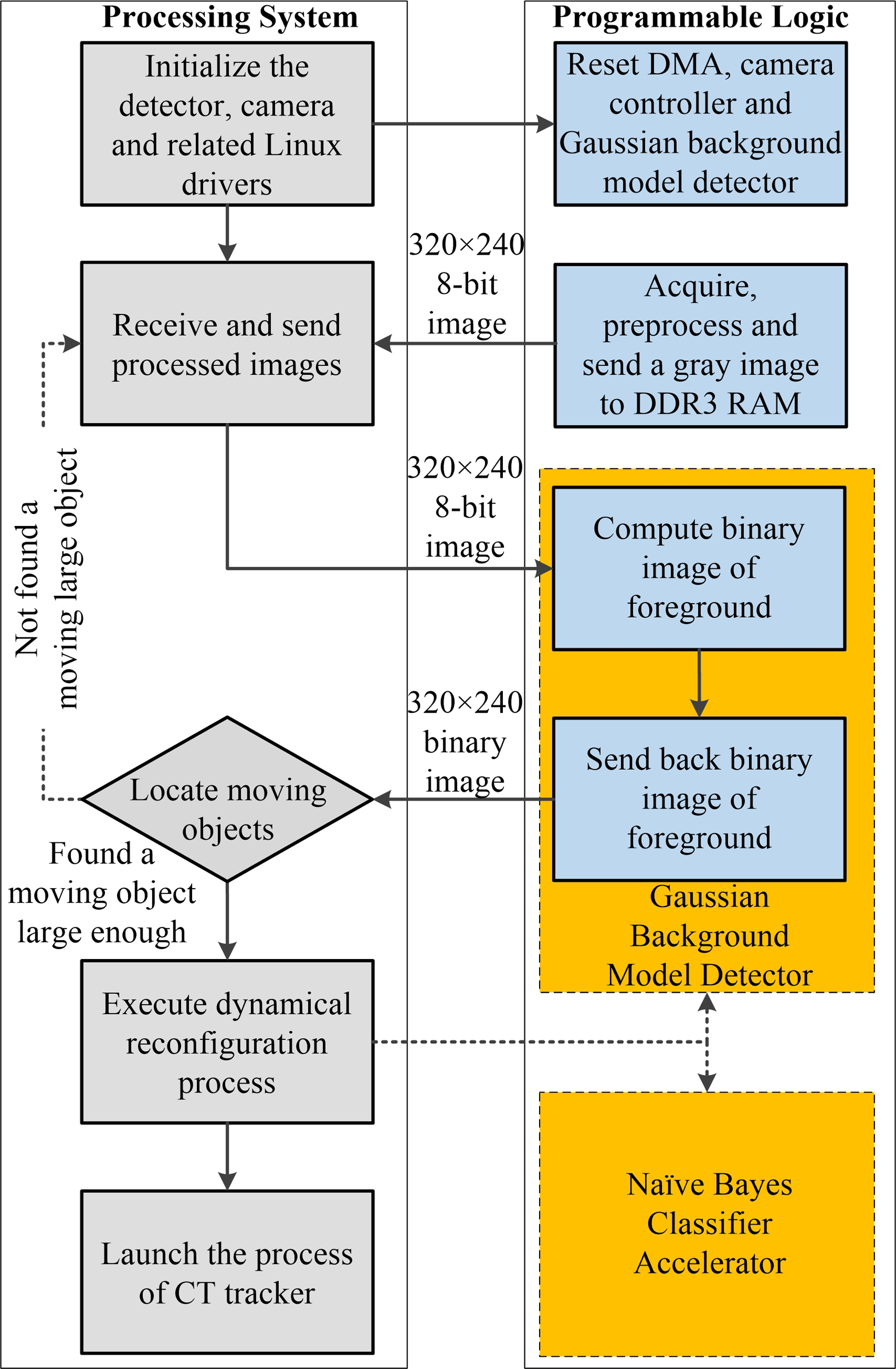
Flowchart of the Gaussian background model-based detection subsystem. The block marked on yellow indicates the reconfigurable area of the PL.
Figure 5 shows the primary structure of the accelerator of Gaussian background model. The 320 × 240 8-bit grey images were serially read into the IP core from an AXI-Stream port. Data of an image was buffered into a slice of block RAM (BRAM) through an AXI-Stream first in first out (FIFO). After receiving an image, the online Gaussian background model computation process was started. To reduce resource consumption and background noise, the original image was resized to 160 × 120 before executing pixel-based foreground detection. The resize, erode and dilate functions were realized on the basis of the video function library provided by Vivado HLS. Finally, the computed binary image was sent out to an AXI-Stream port. The multipliers and adders inside the detection loop were highly parallelized. 2.7 times speed-up was achieved under this heterogeneous architecture, as shown in Table 2.

Diagram of the accelerator of Gaussian background model.
Real-time performance test of detection subsystem at the resolution of 320 × 240.

fps: frames per second.
Design of the CT-based tracking subsystem
The tracking subsystem was designed to successively determine the bounding box of a target, the initial state of which was specified by the detection subsystem. The CT algorithm was adopted in this subsystem as mentioned in the section ‘Heterogeneous architecture of the real-time tracking system’.
According to the analysis results in the section ‘Analysis and evaluation on compressive tracking algorithm’, acceleration mechanisms were designed for the processes of compressive sensing and Naïve Bayesian classifier to achieve real-time performance. The process of compressive sensing is actually a sparse matrix multiplication operation. Thus, it can be speed up with the advanced single instruction, multiple data (SIMD) or ‘NEON’ engine, which is a floating-point coprocessor extension to the PS. Because the NEON engine supports 16-channel paralleled multiply–add operations, the calculation process could be greatly accelerated and the CPU load could be decreased. The process of Naïve Bayesian classifier can be denoted as
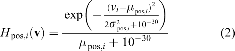


where
Figure 6 shows the major workflow of the tracking subsystem. After getting the initial state of a specified target from the detection subsystem, the tracking subsystem would launch and do initialization works. After sampling candidate patches from an acquired grey image and calculating the integral image, the tracking program would call the NEON engine to complete the process of compressive sensing. Then, feature vectors of candidate patches were sent to the Naïve Bayesian classifier accelerator deployed on the PL. According to the output of the classifier accelerator, the target position can be located and would be used for updating classifier parameters later.

Flowchart of the compressive tracking-based tracking subsystem. The block mark on yellow indicates the tracker deployed on the reconfigurable area of the PL.
The accelerator of Naïve Bayes classifier was also implemented using Vivado HLS tools. Figure 7(b) shows its primary structure. In the proposed system, the dimension of feature vectors m was set to 50 to ensure better discriminative characteristics. The sampling radius γ was set to 15, which led to a candidate patch number of up to 768. Figure 7(a) shows the format of data stream transferred from the PS to the accelerator. Classifier parameters, the number of candidate patches and feature vectors were serially received from an AXI-Stream port and then buffered into a slice of BRAM via an AXI-Stream FIFO. A three-stage pipeline was constructed in the loop for classifier response calculation. The layout of arithmetic units was designed to be symmetrical to realize parallel computing. Finally, the computed maximum classifier response and the corresponding patch number were sent out to an AXI-Stream port.

Diagram of the accelerator of Naïve Bayes classifier for compressive tracking. (a) The format of data transferred from the PS to the accelerator through the AXI-ACP port. (b) Diagram of the accelerator of Naïve Bayes classifier.
Real-time performance test results of the tracking subsystem were as shown in Table 3. Image sequences at the resolution of 320 × 240 and 640 × 480 were entered into the tracking subsystem; 4.3 times speed-up was achieved on the process of compressive sensing using NEON engine; 65.2 times speed-up was achieved on the process of Naïve Bayesian classifier using the FPGA-based customized accelerator. The processes of Naïve Bayesian classifier cost only 15.1% of the whole time when adopting the heterogeneous computing technology. A tracking rate of up to 76.5 fps was achieved with NEON and the accelerator at the resolution of 320 × 240. For the reason that the image resolution does not have great effects on the computational consumption of the CT algorithm, a tracking rate of 46.5 fps was achieved at the resolution of 640 × 480. Although it decreased by 40.4%, it still met the real-time performance demands of the robot.
Real-time performance test of tracking subsystem at the resolution of 320 × 240 and 640 × 480.

fps: frames per second.
Optimization design of the proposed visual tracking system
Though the detection and tracking system designed in the section ‘Zynq-7000 SoC-based low-power real-time tracking system’ was able to meet the functional requirements of our robots, it had obvious drawbacks in FPGA resource utilization rate for two reasons. On the one hand, the resource consumption of an FPGA-based image PS is large in nature due to the high data volume of a digital image. On the other hand, customized accelerators used in the system were designed with high-level languages. Limited by existing compilation techniques, this design method consumes much more resources in exchange for reliability and user friendliness. Table 4 shows the FPGA resource utilization of the two customized accelerators without optimization. Because other essential logic modules of the system also consumed a few FPGA resources, these two accelerators cannot be deployed on the PL at the same time. Moreover, the stability and the performance of an FPGA system may decrease if using more than 70% of the total logic resources. To reduce resource and power consumption, techniques including word length optimization and dynamic reconfiguration were adopted.
FPGA resource utilization rate of the two customized accelerators.

BRAM: block random access memory; DSP: digital signal processor; FF: flip-flop; LUT: look-up table.
Word length optimization of the detection subsystem
Parameters of the adaptive Gaussian background model were originally stored and processed as 32-bit floating-point data, which led to a great amount of BRAM consumption. Considering that the data format of a grey pixel value was 8-bit unsigned char, it was achievable to replace floating-point data with fixed-point data without seriously affecting the detection precision. And it was important to properly choose the word length for each parameter to make a compromise between detection precision and resource consumption. As to the detection algorithm adopted in the proposed system, the optimal solution vector was
To avoid falling into local optimum, the simulated annealing algorithm was adopted to search the optimal solution. An overview of search process is provided in Table 5. The search problem can be denoted as


Principle of the simulated annealing algorithm for word length optimization.

where Cost(

where nTP, nTN, nFP and nFN represent the number of true positive, true negative, false positive and false negative pixels, respectively. Given that the image size in this study was small (320 × 240 or 640 × 480), ratethresh was set to 98.5% to ensure the precision of the detection subsystem. 16
The simulated annealing algorithm accepted candidate solutions with worse precision at a certain probability to avoid trapping in local optimum. Two image sequences with a static background, which had a resolution of 320 × 240 and are 259 frames in total, were chosen as the test videos. The optimization algorithm was executed on MATLAB R2013a, which finally provided the optimal solution

Relationship between the detection precision and word length. (a) Minimum detection success rate in different word length of the expectation when standard deviation was set to floating-point data. (b) Minimum detection success rate in different word lengths of the standard deviation when expectation was set to floating-point data.

Comparison between the foreground images obtained using floating-point data format and fixed-point data format. 33 (a) Input images. (b) Foreground images calculated using floating-point data format. (c) Foreground images calculated using fixed-point data format wbest=[18,10,12,8].
Dynamic reconfiguration of the PL
In comparison with the PS, functional modules running on the PL exist in the form of digital circuits, which leads to two properties. On the one hand, the dynamical reconfigurable property of the PL can be utilized to improve the adaptability of the heterogeneous computing system. According to the desired functions of the system in different working stages, the reconfigurable regions of the PL can be configured as corresponding devices or peripherals. On the other hand, the PL consumes a much higher percentage of dynamic power than the PS. So resources of the PL in working mode also shall be reduced for lower power consumption. As to the proposed system, the detection subsystem and the tracking subsystem did not work simultaneously because of the detection-then-tracking workflow. In comparison with adopting FPGA with larger capacity, it is more reasonable to use dynamical reconfiguration techniques to selectively load the logic to be used in the proposed system.
Dynamical reconfiguration provides a resource reuse method in time domain which can be used in two scales. The full reconfiguration reprograms the whole logic when switching functions of the system, while the partial reconfiguration only reprograms related logic components and does not break work of others. In comparison, the partial reconfiguration has more advantages in efficiency and is suitable for the proposed architecture. Accelerators used in the proposed system were packed into IP cores with the same ports to realize dynamical partial reconfiguration, as shown in Figure 3. Four steps were executed to realize reconfiguration between the detection and tracking stages. First, after specifying the target to be tracked, the program backed up related information into the DDR3 RAM. Second, components connecting to the accelerator were temporarily set to idle state in case of time sequence problems. Three, the partial bit stream file was written to the PL through the PCAP interface. Finally, components connecting to the accelerator were restarted to recovery work.
Table 6 shows experimental results of dynamical reconfiguration. Two banks of the PL were allocated to the black box, in which accelerators would be loaded. Other components like AXI-DMA were deployed outside the black box. Because of the size of the bit stream file, the full reconfiguration time was nearly twice larger than the partial reconfiguration time and the image acquisition interval, which may lead to tracking failure. Thus, partial reconfiguration was more practical for FPGA-based real-time vision applications.
Experimental results of dynamical reconfiguration.

BRAM: block random access memory; DSP: digital signal processor.
Experimental results and discussions
To verify the validation of the proposed heterogeneous system, an MYIRZ-Turn core board carrying Zynq-7000 SoC (XC7Z020) and an OV7670 camera was adopted to implement the detection and tracking system elaborated in the sections ‘Zynq-7000 SoC-based low-power real-time tracking system’ and ‘Optimization design of the proposed visual tracking system’. Three phases of experiments were conducted to test the detection and tracking precision, real-time performance and power consumption of the tracking system.
(1) In the precision test phase, the proposed system was tested with two benchmark image sequences, namely Bike (320 × 240, 119 frames) and Walking (768 × 576, 140 frames). The image sequences were stored in the file system of the proposed system and were read by the implemented visual algorithms. The detection and tracking results were compared with the counterpart of the original MATLAB programs of Gaussian background model and CT. Figures 10 and 11 show the detection and tracking results, respectively. In the detection mode, the down-sampling process, the dilate operation and the erode operation eliminated the detection noise caused by background disturbances. Then, the contour and position of the moving target was located by analysing the connected region. In the tracking mode, the tracking subsystem was configured by dynamic reconfiguration. Then, the CT tracker tracked the target with a rectangle until the target was lost.
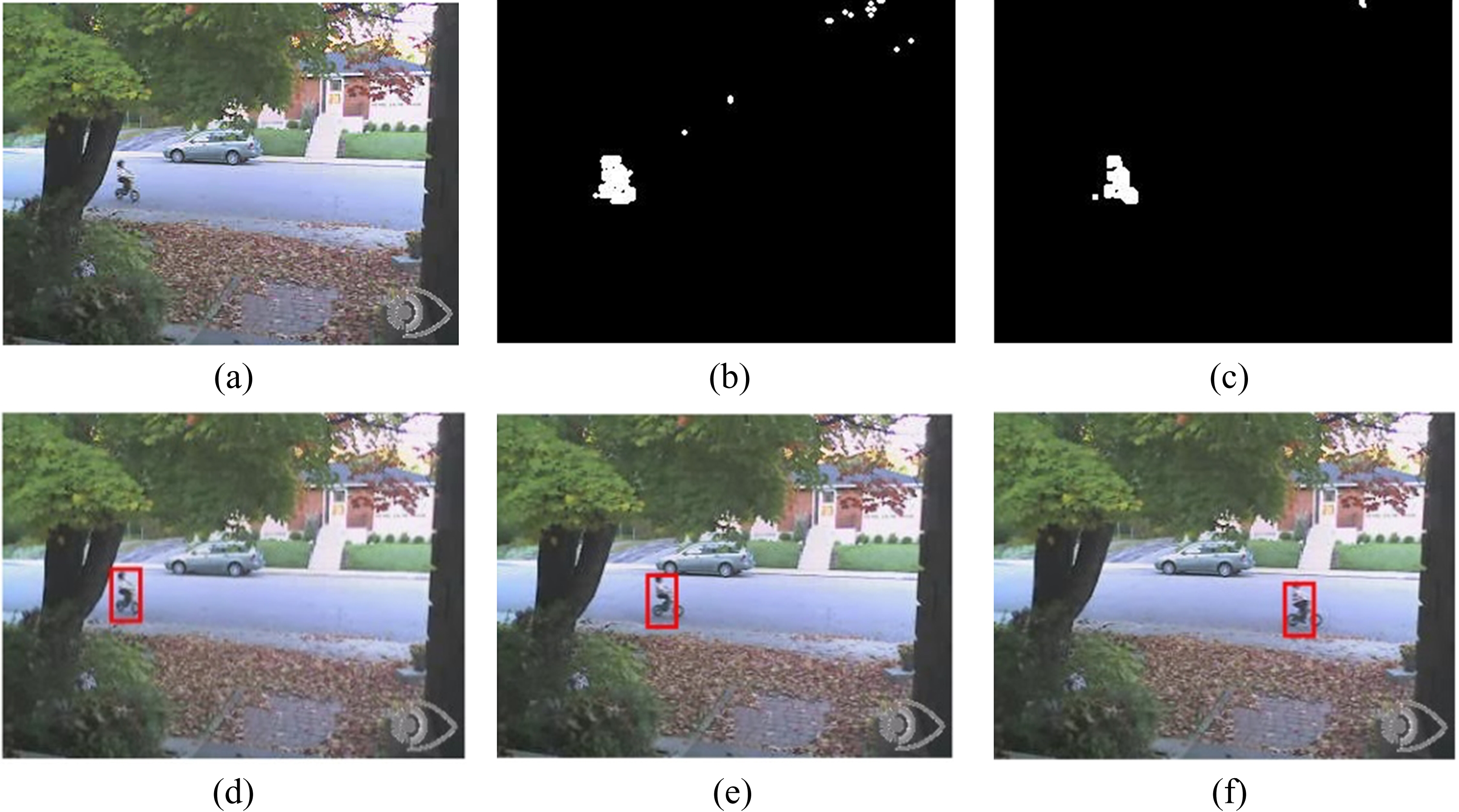
Diagram of detection and tracking experimental results on the image sequences ‘Bike’. 34 (a) Original image. (b) Detected foreground image. (c) Dilate and erode result. (d) Detection result. (e) Tracking result. (f) Tracking result.

Diagram of detection and tracking experimental results on the image sequences ‘Walking’. 33 (a) Original image. (b) Detected foreground image. (c) Dilate and erode result. (d) Detection result. (e) Tracking result. (f) Tracking result.
Two metrics are used to evaluate the precision of the proposed system. The first metric is the success rate of the benchmark sequences. The success rate of a frame is defined as
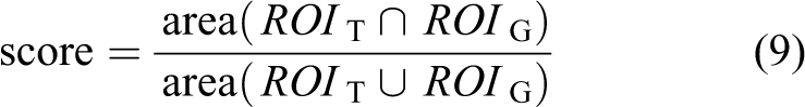
where ROI T is the tracked bounding box, ROI G is the ground truth bounding box and area(·) denotes the number of pixels in the region. If the score is larger than the given threshold (0.5 in this article) in a frame, it counts as a success. The second metric is the centre location error which is the Euclidean distance between the central points of the tracked bounding box and the ground truth bounding box. Experimental results on precision are as shown in Table 7, which verified that the proposed system provided an acceptable detection and tracking precision.
Success rate and centre location error of tracking experiments.

PC: personal computer.
(2) In the real-time performance test phase, 11 benchmark image sequences in different resolutions provided in the study by Wu et al. 35 were adopted to test the tracking rate of the proposed system. The image sequences were stored in the file system of the proposed system and were read by the implemented visual algorithms. The C program of CT rewritten by us on eclipse ran, respectively, on a PC (Intel Core i7-4712MQ, 8 GB DDR3 RAM, Windows 7 64-bit) and a Zynq embedded system (ARM Cortex-A9 Dual-core 667 MHz, 512 MB DDR3 RAM, Linux 3.2.16) to get contrasting data. The proposed system was, respectively, set to software mode (no accelerating mechanisms) and heterogeneous mode. Table 8 shows the test results on real-time performance. The processing rates of the CT tracker on PC, on ARM and on the heterogeneous system are 49.3 fps, 6.48 fps and 61.4 fps, respectively. The kernel load of the PC and the ARMwere 19.7% and 47.2% on average, respectively. The proposed system was able to achieve an average tracking frame rate of up to 89.2 fps under the heterogeneous computing architecture, which was 35.7% faster than a computer equipped with an Intel quad-core processor and was 9.48 times faster than the pure software solution built on the ARM processor. Moreover, the kernel load of the ARM processor using the heterogeneous architecture was decreased to 32.8%, which provided extended room for other robotic functions in the future.
Real-time performance test results of the proposed system.

PC: personal computer; fps: frames per second.
(3) In the robotic test phase, the designed detection and tracking system was installed on a prototype of our amphibious spherical robot to monitor a moving car and an underwater robot, respectively. As shown in Figure 12, the single-board system was able to detect the moving target and then tracked it successfully. In the underwater experiment, the fluctuation of the water surface led to a few false positive pixels. But false detections could be avoided by specifying the region of interest.

Robotic test of the proposed detection and tracking system. (a) Picture of the proposed system. (b) Picture of the robotic test.(c) Original image in the land scenario. (d) Detection result of the image sequence in the land scenario. (e) Tracking result of the image sequence in the land scenario. (f) Tracking result of the image sequence in the land scenario. (g) Original image in the underwater scenario. (h) Detection result of the image sequence in the underwater scenario. (i) Tracking result of the image sequence in the underwater scenario. (j) Tracking result of the image sequence in the underwater scenario.
The proposed system measures 118 × 98 × 45 mm and weighs 125 g. An Agilent 34410A multimeter controlled by C# programs was used to evaluate its average power consumption by continuously measuring the current and voltage value. Test results show that the total power consumption was around 2.99 W. Considering that the battery capacity of our spherical robot was 4800 mAh, it can work in detection or tracking mode for no less than 8 h.
Conclusions
In this article, a low-power real-time detection and tracking system was designed and implemented for our amphibious spherical robot. Given the unique mechanical structure and the specialized application scenarios of the robot, a novel SoC-based heterogeneous computing architecture was proposed for implementations of Gaussian background model-based detection and CT algorithms. Under the presented architecture, the main part of visual algorithms was realized as software programs running on the ARM subsystem, while compute-intensive processes were realized as hardware accelerators running on the FPGA subsystem. Moreover, dynamic reconfiguration and word length optimization were adopted to improve the versatility, adaptability and resource efficiency of the proposed system. Experimental results confirmed that the proposed system had advantages of lightweight, low power consumption and good real-time performance, which was capable of meeting application requirements of our amphibious spherical robot. Its good real-time performance could also meet future demands of the robot in biological monitoring and multi-target tracking.
To the best of our knowledge, this is the first embedded design to implement subtle tracking algorithms on a single SoC for robotic applications. Moreover, the proposed heterogeneous computing architecture provides a feasible solution for mobile vision systems. The design techniques presented in this article, including hardware–software co-development, word length optimization and reconfigurable customized accelerators, may promote the practical use of state-of-the-art tracking algorithms like TLD and MIL.
The system proposed in this article also had some inevitable drawbacks. The detection and tracking precision of the proposed system was directly determined by the adopted vision algorithms. Thus, the detection subsystem could only process videos with static background. The tracking subsystem had the drift problem which limited its precision and would finally lead to tracking failures. Consequently, the detection and tracking results in the experiment section were not entirely accurate. Another problem was that the study in this article mainly aimed at the design and implementation of the robotic vision system. Robotic application functions like visual servoing and autonomous navigation was not realized yet. Our future study will try to improve the tracking precision using state-of-the-art theoretical tools like the conventional neural network. We will also focus on robotic applications and intelligent functions of the amphibious spherical robot.
Footnotes
Author note
Author Shuxiang Guo is also affiliated to Faculty of Engineering, Kagawa University, Kagawa, Japan.
Declaration of conflicting interests
The author(s) declared no potential conflicts of interest with respect to the research, authorship and/or publication of this article.
Funding
The author(s) disclosed receipt of the following financial support for the research, authorship and/or publication of this article: This work was supported by National Natural Science Foundation of China (61503028, 61375094), and Excellent Young Scholars Research Fund of Beijing Institute of Technology (2014YG1611). This research project was also partly supported by National High Tech. Research and Development Program of China (No.2015AA043202).
Appendix
In this appendix the main principles of the CT algorithm and the Gaussian background model was introduced. Figure 13 shows the main components of the CT algorithm. As a discriminative algorithm with an online learning mechanism, CT consists of two stages: tracking and updating.
In the tracking stage, samples of the target of the (n+1)-th frame are sampled in a radius of γ centred with
where s is set to m/4. For each row of
In the updating stage, training samples of the target and the background are sampled according to the tracking result at the (n+1)-th frame (
The Gaussian background model is an effective background subtraction method which are used in robots and surveillance systems. An overview of the Gaussian background model-based detection is provided in Table 9.