
Abstract
Obstacle avoidance represents a fundamental challenge for unmanned aerial vehicle navigation. This is particularly relevant for low altitude flight, which is highly subjected to collisions, causing property damage or even compromise human safety. Autonomous navigation algorithms address this problem and are applied in various tasks. However, this approach is usually overshadowed by unreliable results in uncertain environments. In contrast, human pilots are able to maneuver vehicles in complex situations, in which an algorithm would no offer a reliable performance. This article explores a novel configuration of assisted flying and implements an experimental setup in order to prove its efficacy. The user controls an unmanned aerial vehicle with a force feedback device, where simultaneously an assisted navigation algorithm can manipulate this apparatus to divert the unmanned aerial vehicle from its path. Experiments confirm the authors’ hypothesis that the unmanned aerial vehicle is deviated or maintains the same course at the operator’s will. Unlike conventional controllers that dictate roll, pitch, and yaw, this implementation uses direct mapping between the position represented by the haptic device and the unmanned aerial vehicle. This configuration applies feedback before the unmanned aerial vehicle has reached the position referenced by the haptic device, providing valuable time for the user to make the necessary path correction.
Introduction
Haptics is a field that has received increased attention in the last decade from the scientific community, particularly in potential applications regarding human–machine interaction. 1 Haptic devices can send information to an individual using vibration or force, which is applied to any point of the human body that is covered by skin. Remote-assisted teleoperation is a particular application of haptics that is currently under intensive study due to the growing number of robots that are controlled either through teleoperation 2 or by implementing autonomous algorithms, 3 and in some cases includes force feedback systems that are embedded in the navigation instruments 4 or attached directly to the finger. 5 Some examples are the joystick provided with force feedback that is used to aid physically challenged children for exploring their surroundings with a mobile robot, 6 or the 3-dregrees of freedom (DOF) haptic interface that is used for controlling the position of a robotic arm. 7 Moreover, a particular approach to assisted navigation using force feedback devices is found in the concept of virtual fixtures, which is generalized as visual and haptic cues that facilitate a task as proposed by Rosemberg 8 and thoroughly analyzed by Abbott. 9
Haptic interfaces used in assisted navigation are also available in the form of vibrotactile devices, 10 which have been placed as wrist and chest straps 11 or in the pan and back support of a vehicle seat, providing different vibration patterns that represent useful navigational information such as speed and distance. 12 In a similar application, vibrotactile devices have been placed in belts that have been worn by soldiers, where different vibration modalities inform the soldier about the necessary corrections in their trajectories. The main advantage of this application relies in the fact that the soldier does not have to engage in distracting or time-consuming tasks such as compass reading or map interpretation. 13
Haptic devices have been previously used in the control of individual and multiple unmanned aerial vehicles (UAVs), where position is controlled manipulating the UAV roll, pitch, and yaw. 14 Force feedback is further used in the work done by Brandt and Colton 15 to either avoid impacts with obstacles or inform about the distance to a desired position relative to the UAV. This work proposes an assisted navigation arrangement that can find applications in the growing field of UAV navigation. Similarly, this work could be extended to other applications in the automotive and aviation industries, where quick reaction speed can enhance their performance.
Obstacle avoidance represents an area of continuous interest by the research community as robotic manipulators, unmanned vehicles, 16 and humanoid devices 17 require such algorithms in order to be truly autonomous. Research concerning obstacle avoidance performance dates back to the 1980s 18 and continues today as vision systems push current computational boundaries 19 and researchers design clever tools to enhance current vision systems performance. 20
UAVs are commonly flown manually, since any control algorithm is highly complex to implement. Furthermore, it is well known that typical human reaction times are in the order of hundreds of milliseconds 21 and, for some situations, a faster response is desired. In contrast, the response times offered by artificial intelligence can be effectively used to control an UAV. 22 This approach has experienced a limited range of applications since scenario modeling in complex environments is not a trivial task, particularly when a program has to navigate in harsh environments. For instance, a vision-based computer program may use road texture or surface markings to easily navigate in fair weather; in harsh conditions (i.e. heavy snow), however, this algorithm would not work and more sophisticated approach would be necessary to fly the same vehicle. 23
Nevertheless, UAV control using vision algorithms has been a thoroughly researched topic in recent years. For example, Lee et al. 24 developed a pure image-based visual servoing system for landing and takeoff processes. Although this work has the advantage of not requiring a full 3-D reconstruction, it cannot be used for in-flight pose control. In addition to this, an UAV provided with an onboard camera positions itself using a squared pattern placed on the ground is presented in the research by Mondragon et al. 25 Furthermore, a monocular simultaneous localization and mapping (SLAM) system is used to eliminate odometry drift in the study by Engel et al. 26 This method proved to be robust, but it requires the use of internal sensors like gyroscopes, accelerometers, and cameras. In a similar manner, a SLAM algorithm tracks the pose of the onboard camera and a Proportional Derivative (PD) controller is used for the altitude control in the work done by Blosch et al. 27 Moreover, the full object pose has been controlled; however, this approach requires a stereo setup for 3-D reconstruction and uses inertial measurement unit (IMU) data for rotational dynamics in the research by Romero et al. 28 Note that the abovementioned studies use onboard cameras and sensors to estimate the UAV pose.
Work contributions
This work presents the integration of visual servoing and haptic feedback techniques for enhanced UAV obstacle awareness and avoidance. A vision system tracks the quadcopter pose and manipulates roll, pitch, and yaw to actively control two translational DOF using a single remote camera. The haptic device transmits the position set point to the vision program while providing force feedback to the user in the obstacle avoidance mode. Three experimental scenarios are presented in this article for assessing the system effectiveness: (i) unassisted teleoperation diagnoses the performance of visual servoing and the UAV default behavior; (ii) obstacle avoidance tests the effectiveness of haptic feedback; (iii) human resistance to force feedback proves that the user does not lose control of the UAV from the haptic device. Note that the apparatus setup is identical for the two latter configurations.
A key difference between the presented system and the related work is the placement of the cameras. Engel 26 and Blosch 27 use onboard cameras in hover and path planning exercises, where positioning is performed using a visual SLAM assisted by an onboard IMU. In contrast, this work relies on external cameras for positioning, resulting as a consequence in the UAV weight reduction, and further limiting its potential range. This approach is presented in a previous work, 29 where the tracking algorithm is used to control the UAV through a predefined path, where a set of points acted as references.
The remainder of the article is organized as follows: the “System architecture” section provides an overview of the devices used in this work, their interactions, and the general setup of the experiments. The devices are thoroughly examined in the two following sections. The “Unmanned aerial vehicle visual servoing” section describes the quadrotor and its positioning algorithms, while the “Kinematics and workspace of the haptic device” section studies the haptic device, its kinematics, and force feedback behavior. The “Experimental work and results” section describes the performed experiments and discusses the obtained results. Finally, the “Conclusions” section presents a synopsis and suggestions for further work.
System architecture
The experimentation performed in this work is based on the notion that a certain region of the UAV workspace has to be avoided. For this purpose, a force feedback device delivers quick corrections to the UAV reference position. The corrections are based on an algorithm that calculates the haptic device position and compares it to the location of a predefined region of avoidance. When the end effector enters the abovementioned region, the haptic interface generates a force that is capable of moving the user out of this area. This force accomplishes a dual purpose: to signal the user that the undesired region has been entered and to correct the end effector trajectory if the user does not resist the force. Among the applications of the presented system includes the UAV navigation. Furthermore, search and rescue robots could use the proposed system to keep the UAV away from designated regions (i.e. where rubble is unstable). 30,31 However, the arrangement can also be used in surgery, where tool positioning is critical and the concept of virtual fixture can be used to avoid important tissue (i.e. arteries and nerves).
Human input modifies the haptic device position that is used as the UAV reference. Direct mapping keeps the UAV in a safe position in case of communication failure, which represents a problem in robotic teleoperation. 30 The communication is one-way, flowing from the haptic device to the UAV. Note that the vision algorithm works even if the position reference is not updated. This work proposes the use of accelerometers for sensing the position of the haptic device end effector. Similarly, the UAV position is obtained using a vision program. Figure 1 also details the control scheme of the UAV, where the configuration controls the position and limits speed, due to the fact that the vision algorithm only works at low speed. Note in Figure 1 that the obstacle detection algorithm is placed in the haptic device control loop rather than the UAVs. This is possible only because the workspace of the haptic device is mapped into a designated UAV flight zone. Such configuration introduces an avoidance algorithm that is different from the related work. In projects of similar nature found in the literature, force feedback is triggered by the actual UAV position, which is effective to move the drone out of the undesired area; but incapable to prevent the entrance to this zone in the first place. In contrast, feedback triggered by the haptic device position reduces or avoids entirely the entrance of the UAV in the undesired region. This is possible because the control loop described in Figure 1 avoids delays related to communication, the vision algorithm, and the UAV dynamics, which are meticulously analyzed in the following section.

Control loops within and between the haptic device and the UAV. UAV: unmanned aerial vehicle.
Unmanned aerial vehicle visual servoing
The work presented in this section is related to the visual tracking and servoing of an UAV. This article uses an AR.Drone Parrot quadrotor unit for experimentation purposes as shown in Figure 2. The drone and the haptic device are controlled from different computers that communicate through Wi-Fi.

Experimental UAV where a texturized parallelepiped is placed on the top of the drone. UAV: unmanned aerial vehicle.
Following the approach proposed in the study by Barajas et al. 29 for the vision algorithm, this work places a boxed object with a distinctive design in each face over the drone (see Figure 2). Furthermore, as illustrated in Figure 3, a plane tracking method is used to identify a single face of the cuboid for any given image frame. Since the box can rotate relative to the camera, a criterion to select the most visible face is established. In this work, homography decomposition is further used in order to obtain the 3-D reconstruction of the planar surface.

Object tracking strategy.
The UAV is controlled using a position-based visual servoing system, which has been validated in the study by Barajas et al. 29 The feedback of the control loops is the current 3-D pose of the object that is further used to estimate the roll, pitch, yaw, and vertical speed that are needed to reach a reference position and orientation.
Note that the application presented in this article is restricted to 2-D spaces which are mapped to translation movements. Nevertheless, disturbances will demand that the aerial vehicle makes use of all available actuators to reach a provided reference.
Cuboid tracking
This work considers a cuboid as the tracked object in order to obtain the 3-D pose of the UAV. Note that the cuboid is the minimal solid object with planar faces that can be tracked from all directions with the minimal number of planar faces. According to the research by Barajas et al., 32 a cuboid C can be expressed in terms of the six planar faces that conform it as follows

where

Note that from the set of faces of cuboid C, only a subset of one up to three faces will be visible at anytime, assuming that the cuboid is always visible by the camera. Moreover, there will be some cases in which, even if the face is visible, tracking will not be possible due to sampling. For example, Figure 2 shows a pose where only one planar face should be tracked. Although other faces are also visible, sampling will not allow the plane tracker to converge into a solution.
To determine the faces that are visible and suitable for tracking, the approach in the work done by Barajas et al. 32 is used, where it is demonstrated that the most visible face can be obtained using the following expression

where
Although equation (3) presents an approximation assuming that all faces of the cuboid are equally sized, in practice, this has no major effects. Similarly, sampling errors do not affect traffic performance when non-visible faces present a reasonable area.
Face tracking and homography decomposition
After the most visible face has been identified, the next step in the process is to track that individual face using a plane tracking method. In particular, the efficient second-order minimization (ESM) method proposed by Malis
33
was used. This method has proven to provide higher convergence with less global error,
33
when the current parameters

where

Multiple elements of the tracking and servoing system require the 3-D pose of the object, which can be recovered in multiple ways. 35,36,37 Since the method followed in this work is based on plane tracking, 3-D reconstruction is performed through homography decomposition.
Since the real dimensions of the planar faces of the tracked object are provided and the intrinsic parameters of the camera are known, it is possible to obtain a full 3-D Euclidean reconstruction for a planar face that provides its current homography, which is obtained from the output of the ESM tracker method. For this reason, the homography decomposition is performed over the tracked plane.
Homography decomposition deals with reconstructing the 3-D pose of a planar surface given its projection on the image plane. Note in equation (5) that only eight parameters are used to accomplish plane tracking, which are mapped to the 3 × 3 homography transform.
As part of the reconstruction method, the 3-D pose of the plane center is estimated using the transformation matrices in a similar way to equation (2), where the only difference is that the transform to be used is now between the current face and the object center. This work assumes that no distortions caused by the lenses occur, also known as the camera pinhole model, represented in equation (6)

where fx and fy represent the focal length, while cx and cy constitute the principal point. Similarly, the transformation matrix of extrinsic parameters

Let the individual elements of matrix
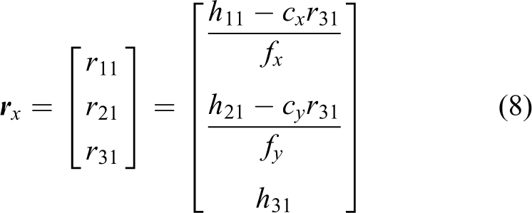

and

Having correctly determined the pose, the controller manipulates the UAV’s local roll, pitch, yaw, and vertical speed. Roll and pitch control allows the UAV to move on the horizontal plane, and vertical speed is used solely to increase or decrease the height of the drone. Note that for this application, yaw is fixed but can be manipulated if necessary. The position control relative to the floor (XY plane) is directly mapped to the 2-DOF haptic input (see “Kinematics and workspace of the haptic device” section) using a cascade controller (see Figure 1). At the first level, a PD controller manipulated the speed in X and Y at which the vehicle should move. In the nested loop, a Proportional Integral Derivative (PID) controller manipulated the roll and pitch variables of the drone. This configuration assures low velocity of the UAV and therefore a reduced inter-frame change in the camera, which is necessary for the correct functionality of the vision algorithm.
One advantage of this control system is that it allows a fine manipulation of the drone speed as one PID controller is dedicated to this sole purpose, that is, the control variable of the inner loop. In this way, the first controller sets the X and Y speed reference and the outer loop will control the speed that is proportional to the distance from the reference (up to a maximum value). The integral component of the speed controller plays a key role when perturbations are present for roll and pitch motion, particularly in case of wind gusts, since it reduces the error by enhancing the manipulation of the UAV. In a similar manner, the derivative component of the roll–pitch controller aids the speed reduction in situations where the drone moves in a parallel direction to the wind. Proportional controllers are used for the yaw and vertical speed, since built-in orientation and height control are stable for tracking. Figure 1 shows the proposed controller for yaw, where a similar algorithm is used for height control.
Kinematics and workspace of the haptic device
A novel haptic device that has been previously studied in the work done by Roberts and Rodriguez-Leal 38 –40 is used in this article to provide force feedback to the user. The apparatus consists of a compliant seven bar mechanism with 2-DOF (see Figure 4(a)). The maximum force feedback of this device is set up with a magnitude that allows perception by the user and to yield the motion of a relaxed finger but is unable to exceed the force that is applied by an average user, which is in the order of 40 N. 41 Most structural components of the prototype (see Figure 4(b)) including the base and the links were constructed using a commercial 3-D printer. The links are interconnected with the use of revolute joints. This device considers two active joints that are driven by DC motors. The apparatus is constructed with two three-axis accelerometers as shown in Figure 4(b) that are placed in links 1 and 5. The contact interface between the user and the mechanism is the ergonomic edge of the platform (see Figure 4(a)), which is referred in this work as the end effector.

(a) Mechanism schematic and (b) mechanism prototype.
In this work, scalars, vectors, and matrices are represented as lowercase italics, lowercase bold italics, and uppercase bold italics, respectively. Furthermore, Greek letters and uppercase characters depict angles and points of interest in the mechanism workspace, respectively.
Consider the vector representation of the mechanism in Figure 5, where vector

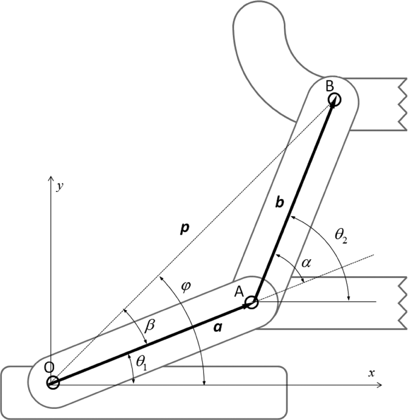
Vector representation of the mechanism variables depicting angles and points of interest.
where θ1 and θ2 represent the angular position magnitudes of the active joints. Consider that s and c denote the sine and the cosine of the respective angle. Furthermore, l refers to the dimensional parameter of vectors

(a) Mechanism workspace and region used in experimentation depicting the virtual fixture. (b) Virtual fixture closeup within the mechanism workspace.
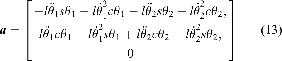
For this application, it is observed that accelerometers offer some benefits over encoders. For example, the absence of moving parts reduces the number of mechanical components and simplifies design complexity 42 or provides improved resolution compared to encoders of similar cost. A drawback, however, is a higher computational complexity, since the sensors do not provide direct information about the joint angle and it has to be calculated from the gravity for each axis of the accelerometer. This is further complicated by the effect of linear velocity and acceleration, as both have an influence in the accelerometer readings and therefore have to be taken into account to accurately estimate the position. The velocity is obtained by differentiation of equation (11), resulting in

where
where
Furthermore, the force vector applied to the user is the result of the torque of the active joints as follows

where τ1 and τ2 represent the torques applied to the links 1 and 5 by the motors (see Figure 4(a)). Consider that τ1 and τ2 operate at full torque, clockwise and counterclockwise, respectively, since this configuration assures that the force does not oppose the mechanism weight vector. Note that the torque of the upper link has a magnitude five times higher than the lower link in the used prototype; this is the result of the belt working as a speed reducer with a 5:1 ratio. The result of the abovementioned characteristics creates the force pattern described in Figure 6 where the average force is approximately 6 N.
Equation (14) can also be used to assess the maximum static force that the mechanism can apply at any given configuration. This parameter is of particular interest as the safety of human interactive devices represents a topic of interest in robotics. The maximum force exerted on the end effector is determined as follows
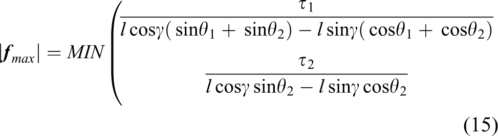
Equation (15) is a function of the torques applied by the motors (τ1 and τ2), the joint angles (θ1 and θ2), the links length l, and the direction of the reactive force γ. The evaluation of equation (15) for
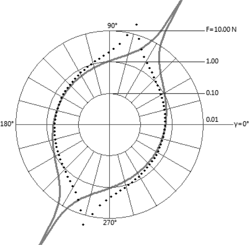
Maximum feedback force varies as a function of direction.
Slight variations in force direction enable different forms in which the haptic device deflects the incoming end effector. For example, any user approaching the virtual fixture in the direction of the vector v1 will encounter a force Fr1 (see Figure 6) opposing the movement, and when approaching in the direction of the vector v2 will experience a force Fr2 that does not oppose the movement but tries to deviate the user sideways. The difference in haptic feedback is strong enough to be perceived by the user but has a negligible effect in the change of trajectory as the following experiments will show.
Experimental work and results
The user manipulating the haptic device is instructed to move in rectilinear paths along the X-axis back and forth for 2 min, where the beginning and destination of the path are on opposing sides. The first experiment can be seen as a simple teleoperation exercise where the force feedback in the haptic device is turned off and the position reference is given to the UAV controller. Oscillations and delays that occur in this setup can be considered as a normal behavior for the vision-controlled UAV. In the second experiment, the haptic feedback is activated. The user experiences force feedback as soon as the end effector enters the virtual fixture region; this force tries to move the user out of the mentioned region. For this experiment, the operator is asked to avoid the obstacle, but no information is given about its location or dimensions, therefore the user has to rely on the force feedback to avoid the obstacle. In the third and last experiment, the user is asked to force a rectilinear path similar to the first experiment regardless of any feedback applied by the device. The purpose of this last experiment is to demonstrate that the configuration only assists in navigation and does not take control over the individual. Note that this experiment uses a mapping between the workspaces of the haptic device and the UAV. This mapping amplifies the user movement 25-fold as the experiment takes place in an area with a length of 80 mm in the haptic device that corresponds to 2 m in the UAV (see Figure 6). Note that Figures 8, 10, and 12 show only a subset of the trajectories measured in order to maximize image comprehensibility.

(a) Haptic device (reference) and (b) UAV paths for unassisted teleoperation for a simple linear trajectory. UAV: unmanned aerial vehicle.
Experiment 1: Unassisted teleoperation
For the first experiment, the haptic feedback remains deactivated. The user flying the haptic device is asked to move along the plane in repetitive paths for 2 min, first moving on the positive X-axis direction and then returning to repeat the cycle until the time is exhausted. This process is repeated generating 18 and 16 trails in each attempt, Figure 8(a) shows 5 trails. Note that both back and forth trajectories are plotted and have a similar behavior due to the absence of force feedback. The end effector position in the haptic workspace is adjusted to the UAV workspace and transmitted as the position reference to the controller. Figure 8(b) includes the actual position of the UAV. This experiment is designed to test the vision system and the UAV control capabilities; the resulting trajectories are further used as references to assess the behavior of the following experiments. Note that the UAV oscillates due to the presence of unexpected air currents.
Experiment 1 evaluates the UAV performance during its interaction with the haptic device. The system behaved as desired, since the visual servoing system is based in standard plane tracking that assumes small inter-frame displacement. Nevertheless, the low-speed constraint has a significant effect in the time the drone reaches the provided reference. However, this delay assures a robust tracking behavior. Similarly, this delay does not affect the system ability to evade obstacles since the deflection algorithm runs in the haptic device, before the position reference is transmitted to the UAV (see Figure 1). Position tracking and speed stability can be further analyzed in Figure 9(a), where the UAV position and the reference set by the controller are denoted as PV and SP, respectively. Note that the tracking error is in the order of centimeters and the speed does not exceed 0.005 m/s. Roll and pitch are the manipulated variables and during the experiments rarely took values greater than 10°. Conversely, yaw and height are defined to be static (see Figure 9(b)); however, their actual values varied due to air currents and other external disturbances, registering around 5° for yaw and 3 cm for height.

(a) Roll and pitch control UAV position in the X- and-Y-axes. (b) UAV height and yaw are referenced to be static, natural deviations occur as the quadcopter moves in other DOF. UAV: unmanned aerial vehicle; DOF: degrees of freedom.
Typical UAV uses roll, pitch, and yaw to control position. For this experiment, the user controlled the end effector position directly with the haptic device. This configuration was reported by the users to have a counterintuitive feeling compared to the use of joysticks. Direct position control may be difficult to implement in large environments, although shows the benefit of not needing a line of sight between the user and the UAV where the algorithm calculates the drone position. This has useful applications in low visibility environments.
Experiment 2: Assisted teleoperation
Similar to the previous experiment, the user is asked to move the haptic device in trajectories alongside the X-axis within the limits of the workspace for 2 min. Force feedback is turned on and the user does not resist it as it is instructed to avoid the virtual fixture. The experiment settings allow the user to reach the destination after the force has ejected the end effector from this obstacle. The force exerted by the apparatus and the lack of resistance by the user produce a measurable deviation. This is the expected result as it shows the potential of the algorithm to effectively modify the position of the UAV without taking full control of the vehicle.
During this experiment, force feedback moves the end effector away from the virtual fixture; note that left-to-right assisted trajectories in Figure 10(a) are symmetrical when compared to their right-to-left counterparts in Figure 10(b). This behavior is of particular interest and not necessarily expected since the force applied throughout the obstacle is not symmetrical, but skewed leftward. This result shows the robustness of haptic signals in assisted navigation.

Multiple attempts to enter the virtual fixture while force feedback is activated. (a) Left-to-right and (b) right-to-left trajectories show similar behavior.
The position reference is transmitted to the UAV controller. The UAV trajectory for this experiment is visibly modified by the haptic feedback, resulting in the effective avoidance of the virtual fixture in Figure 11(a). Note that all depicted paths have distinctive oscillations that are not product of the position reference. These variations can be attributed to the effect of small air currents to the UAV dynamics.
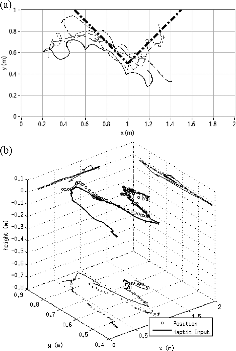
(a) Visible deviation of the UAV in assisted teleoperation and (b) 3-D depiction of the UAV flight and its position reference for a single pass. UAV: unmanned aerial vehicle.
One the trajectories of Figure 11(a) is thoroughly examined in Figure 11(b). The 3-D plot shows a tracking performance similar to the previous experiment; however, higher altitude variations are reported. This can be explained as a consequence of the UAV making stronger corrections while attempting to follow the reference. Note, however, that the controller limits the UAV speed regardless of the amount of change in the position reference. This assures stability as the drone approaches its new reference even under the presented disturbances.
Experiment 3: Assisted teleoperation with user override
The force feedback mode adopted in the second experiment is used in this test. For this experiment, the user is asked to override the machine attempts to modify the path out of the virtual fixture zone. As with the previous experiment, the force produced by the apparatus will depend on the position in which the user approaches the obstacle. Figure 12(a) shows the obtained results for the haptic device; the trajectory differs from the previous experiment as it resembles the trajectories produced for the configuration with no haptic feedback. Unlike the first run, the user detects the device and attempts to adjust the trajectory in this experiment. The applied force by the haptic device is easily exceeded by an average human user; this feature avoids coercion by the device to the user, maintaining the latter as the true driver of the vehicle. A weak robot also assures safety, which is a priority in any form of human–machine interaction. The reference position sent to the UAV controller and the path traveled by the drone itself also show high resemblance to the first experiment as shown in Figure 12(b). Note that in the mentioned figure, haptic feedback produces a deviation that is visible at around 0.85 m. Although significantly smaller than the second experiment, this kind of deviations may have undesired consequences in applications where precision is essential, such as surgical procedures. Therefore, the authors recommend that future work should focus in the safety of such applications. Instability in the haptic device is not an issue of concern since the human hand works as an overdamped mass-string-damper system that absorbs enough energy to assure passivity even if the haptic device is operated at 100% of its capability. 43
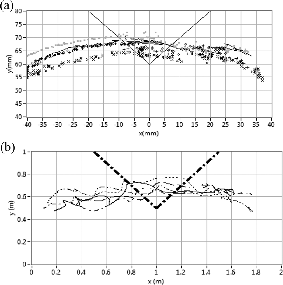
Active resistance to the mechanism influence produces trajectories in (a) the haptic device and (b) UAV that are similar to experiment 1. UAV: unmanned aerial vehicle.
The system capability to deviate the user from the virtual obstacle is clearly demonstrated in experiment 2 compared with the control experiment 1. Furthermore, experiment 3 shows that the user can overpower the haptic device and thus maintain control over the UAV. However, in order to provide further proof of the system validity, the mean time in which the user navigates into the avoidance region is measured. The measurement yields that the user stays on average 1.17 s in each pass through the virtual obstacle in experiment 1. Moreover, the times in which the operators enter a depth greater than 4 mm and 8 mm into the virtual obstacle are measured as 0.66 s and 0.24 s, respectively, in experiment 1. For experiment 2, the time into the virtual obstacle is diminished albeit slightly to 1.02 s. However, experimenting this experiences a steep reduction of the time in which the operator enters more deeply into the virtual obstacle, marking 0.1 s and 0 s for depths of 4 mm and 8 mm, respectively. For experiment 3, the times in which the operator enters the virtual obstacle rise back to 1.26 s. Similarly, this trial records times of 0.58 s and 0.14 s as the time passed inside the 4 mm and 8 mm marks. This clearly shows that the operator ultimately decides the path taken by the haptic device and therefore the UAV. All the abovementioned time values are presented in Table 1. This table also introduces the index no that considers the time and depth spent inside the virtual obstacle according to the following equation

Experiments performance.

where ts represent the time spent inside the virtual obstacle, while t4 and t8 measure the time spent at a depth of at least at 4 mm and 8 mm from the surface, respectively. Note that the latter values are weighted more heavily in order to punish the trajectories that do not deviate from the virtual obstacle. The value that results from the sum is normalized to the control experiment 1. Note that ts further verifies the effect of haptic feedback as valid trajectory modifier only when the user accepts its input. Alongside Table 1, the abovementioned results are presented in Figure 13 in which it is possible to see the significant reduction of time spent in the virtual object when haptic feedback is applied, especially for depths greater than 4 mm.

Mean time in seconds spent by the user within the virtual obstacle boundaries and into depths of 4 mm and 8 mm from the obstacle surface. The weighted index is function of these three times as defined in equation (16).
Conclusions
An assisted teleoperation system using haptic feedback is presented in this article. A vision-only method is proposed to control an UAV generating the position reference using direct mapping between the haptic device and the UAV workspaces. The haptic interface is able to provide a force feedback that the user may override at will.
The article presented the closed-solutions for the device kinematics and obtained the workspace of the haptic interface.
Three different types of experiments were performed. Starting with simple teleoperation, the UAV proved to be stable with the vision-based control. When haptic feedback is turned off, the controller works as a simple teleoperation device. The response times observed correspond to the expected magnitudes for this kind of applications, where the presented behavior is acceptable even with the complexity produced by the vision-based control.
The second experiment consisted in the application of force feedback without conscious opposition from the user. Obstacle avoidance becomes active when haptic response is turned on. For this experiment, using assisted teleoperation, it is possible to observe the effectiveness of the device as quick corrections were made. This moved the UAV position set point and translated the UAV out from the exclusion zone effectively.
The third experiment consisted on conscious opposition by the user. Even while the force created a visible deviation, this indent is minimal as the user is able to override the device and move the UAV as desired.
It has been successfully demonstrated that active haptic feedback plays an important role in UAV navigation as an algorithm can react quickly to an impending danger such as an obstacle. Human factor is important in navigation tasks where context awareness and complex information interpretation is necessary.
Haptic devices have the potential to become valuable assets in UAV control. Low altitude flight and the interaction with people require the implementation of safety features; this will be possible since an algorithm will always be ready to make decisions faster than normal human reaction. This opens several applications for UAVs that are otherwise restricted for safety reasons (e.g. a disaster situation where a drone has to enter a room to look for survivors).
Suggestions for further work include algorithm design for specific applications such as unexplored indoor navigation and a further study of stability for high UAV speeds.
Footnotes
Acknowledgements
The authors would like to acknowledge Consejo Nacional de Ciencia y Tecnología (CONACyT), the Laboratorio de Robótica del Área Noreste y Centro de México, and the Robotics Research Chair at Tecnolgico de Monterrey for supporting this research.
Declaration of conflicting interests
The author(s) declared no potential conflicts of interest with respect to the research, authorship, and/or publication of this article.
Funding
The author(s) disclosed receipt of the following financial support for the research, authorship, and/or publication of this article: This work was supported by Consejo Nacional de Ciencia y Tecnología (CONACyT), the Laboratorio de Robótica del Área Noreste y Centro de México, and the Robotics Research Chair at Tecnolgico de Monterrey.