
Abstract
The 3-P(Pa)S mechanism, based on the 3-Prismatic-Rotational-Spherical (PRS) mechanism, but with three of its revolution joints and passive links replaced by parallelogram structures, provides improved stiffness and better constraint of undesired Degree of Freedom (DOFs). The general method to establish the error model of a 3-P(Pa)S mechanism is simplifying it to a 3-PRS mechanism, which fails to account for the influence of the errors in the parallelogram structure. In this article, the error model of a spindle head based on 3-P(Pa)S mechanism was established. By projecting the structural errors of the parallelogram structure to the structural errors of a 3-PRS mechanism which is simplified from the 3-P(Pa)S mechanism, the errors of the parallelogram can be included into the model. Then, the projecting method was verified by an experiment on the spindle head to prove its correctness. Based on the error model, sensitivity analysis of the structural errors was carried out. According to the characteristic of the mechanism, two new sensitivity indexes, standardized signed local sensitivity index and standardized signed global sensitivity index, were proposed which can better reflect the influence of the structural errors on the end effector error and can also indicate whether some structural errors have similar or opposite influence on the end effector. Then, the most sensitive errors were derived and the sensitivity distribution within the workspace of the spindle head was analyzed. Additionally, two possible applications based on the sensitivity analysis were proposed to reduce the error of the spindle head.
Keywords
Introduction
Compared to the conventional serial type mechanisms, parallel mechanisms are expected to have higher stiffness and perform with greater dexterity 1 –4 and have been widely applied in the design of machine tools. 1,5,6 In the last decades, a series of less-freedom parallel mechanisms were introduced as spindle head for machining, 7 –12 which can be installed on a serial type mechanism to realize 5-DOF movement, among which a series of the most widely used spindle heads are based on the 3-PRS mechanism. 13,14 Additionally, some parallel mechanisms have been designed based on the parallelogram structure, which can provide higher stiffness and constrain undesired degrees of freedom. 15,16 Therefore, a new less-freedom parallel mechanism is proposed based on the 3-PRS mechanism, in which three revolution joints and passive links were substituted by three parallelogram structures. Because of the existence of the parallelogram, the entire mechanism is named as 3-P(Pa)S mechanism, where “Pa” denotes the parallelogram structure.
Since there are more joints and links in the parallel mechanism that causing errors, the accuracy issue of the parallel mechanism is always one of the most important issues. Error modeling is the first step to investigate the error of a mechanism. The general error modeling method for this kind of parallel mechanisms with parallelogram structure is to replace the parallelogram by a link and a revolution joint since they are considered equivalent in the ideal condition. 17 For the 3-P(Pa)S mechanism, when the parallelogram structure is replaced, its error model can be simplified to the error model of a 3-PRS mechanism, which is well established. 18 –21 However, it is an incomplete error model since the influence of the errors in the parallelogram structure is not included, which may reduce the accuracy of the model.
In order to improve the error model, the errors of the parallelogram structure must be well considered. Huang et al. 22 established the error model of a 3-DOF parallel spindle head with parallelogram structure. By connecting two middle points on two opposite parallel links of the parallelogram and assuming the other two links of the parallelogram are uniformly parallel to each other, the errors of the four links of the parallelogram structure were transformed into the error between the two middle points. Chen et al. 15 established the error model of a 4-DOF selective compliance assembly robot arm with parallelogram structure using the same method. However, this method cannot to be used for the 3-P(Pa)S mechanism since some parts of the parallelogram structure in 3-P(Pa)S mechanism are rigid bodies but not links. Therefore, a new integrated error model including the errors of the parallelogram structure is needed for the 3-P(Pa)S mechanism.
In this article, the error model of a parallel type spindle head based on 3-P(Pa)S mechanism was established. To include the errors of the parallelogram structure into the error model, firstly, the error model of a 3-PRS mechanism simplified from 3-P(Pa)S mechanism was established. Then, two individual chains, the PRS chain and the P(Pa)S chain, of the 3-PRS and 3-P(Pa)S mechanism were analyzed, and the united kinematic equations of the PRS and P(Pa)S chains were established. An error projecting method was proposed to project the structural errors of the parallelogram to the structural errors of the 3-PRS mechanism. During the projection, the characteristic of the parallelogram was considered and the projection equation is simplified. Therefore, the errors of the parallelogram were included into the error model. Then, a verification experiment was carried out on the 3-P(Pa)S spindle head to verify the correctness of the error projection method.
Based on the error model, sensitivity analysis is necessary for the parallel mechanism, which can estimate the influence of structural errors on the error of the end effector, so the most sensitive structural errors can be derived and be paid more attention in the design, manufacture, and assembly process. Many researchers have done meaningful researches in sensitivity analysis. 23 For instance, Fan et al. 24 analyzed the sensitivity of the 3-PRS mechanism and derived the most sensitive errors. Additionally, some other researchers also proposed specific sensitivity indexes for a certain kind of mechanism to guide the design process. 25,26 Li et al. 27 proposed a new sensitivity index, named as general global sensitivity fluctuation index, to reflect the error fluctuation within the workspace.
In this article, on the basis of the proposed error model, the sensitivity of the structural errors of the 3-P(Pa)S parallel type spindle head, especially the errors of the parallelogram structure, was analyzed. Firstly, the local sensitivity index (LSI) and the global sensitivity index (GSI) of the structural errors were calculated. Then, according to the characteristic of the 3-P(Pa)S mechanism, two new sensitivity indexes, standardized signed local sensitivity index (SSLSI) and standardized signed global sensitivity index (SSGSI), were proposed, which can better reflect the influence of the structural errors on the end effector and can also indicate whether some structural errors have similar or opposite influence on the end effector. Based on the new index, the most sensitive errors were derived. And the sensitivity distribution within the workspace of the spindle head was analyzed. Finally, two possible applications of SSLSI and SSGSI were proposed to reduce error of the spindle head.
The structure of the article is demonstrated as follows: the structure of the 3-P(Pa)S spindle head is introduced in “Structure description” section. Then the error modeling of the 3-P(Pa)S mechanism is presented in “Error modeling of the 3-P(Pa)S parallel type spindle head” section. In “Verification of the error projection” section, the proposed error projecting method was verified by an experiment on the spindle head. In “Sensitivity analysis” section, sensitivity analysis is carried out based on the error model. The final section is the conclusion.
Structure description
The structure of the 3-P(Pa)S parallel spindle head is shown in Figure 1, and Figure 2 is the schematic of the spindle head. It is composed of two platforms (steady platform and moving platform) and three chains. The chains are uniformly distributed along the circumference of the platforms, and the angle between each pair of chains is 120°. There is a parallelogram structure in each chain. One side of the parallelogram is connected to a prismatic joint and its opposite side is fixed to a bar at the end of which is a spherical joint. The guide way of the prismatic joint is located on the steady platform and the spherical joint is located on the moving platform, and the axes along the guide ways are denoted by Zm1-, Zm2-, and Zm3-axis. Three actuators were installed on the prismatic joint to control the pose of the mechanism. At the equilibrium pose, the axial line of the spindle is along the Z-axis. Compared to 3-PRS mechanism, 3-P(Pa)S mechanism substitutes the passive link and rotational joint with the parallelogram structure, so the stiffness can be improved since the chains of the mechanism become stronger. Additionally, because of the existence of the parallelogram structure, the undesired DOFs of the chain can be restrained.

Structure of the 3-P(Pa)S parallel type spindle head.

Schematic of the 3-P(Pa)S parallel type spindle head.
Error modeling of the 3-P(Pa)S parallel type spindle head
The 3-P(Pa)S mechanism can be simplified to a 3-PRS mechanism in the ideal condition. Because of the symmetry, we only investigate chain 1 in its own plane, as shown in Figure 3. In the figure, it can be derived that

Simplification of chain 1 of the 3-P(Pa)S mechanism.
Error model of the 3-PRS mechanism simplified from the 3-P(Pa)S mechanism
The structure of the 3-PRS mechanism simplified from the 3-P(Pa)S mechanism is shown in Figure 4(a), in which the original 3-P(Pa)S mechanism is shown by dot line. Except for the parallelogram structure, the two mechanisms are the same, so the nomenclatures in the 3-PRS mechanism can also be applied to the 3-P(Pa)S mechanism. The coordinate frames were established as shown in Figure 4(b).
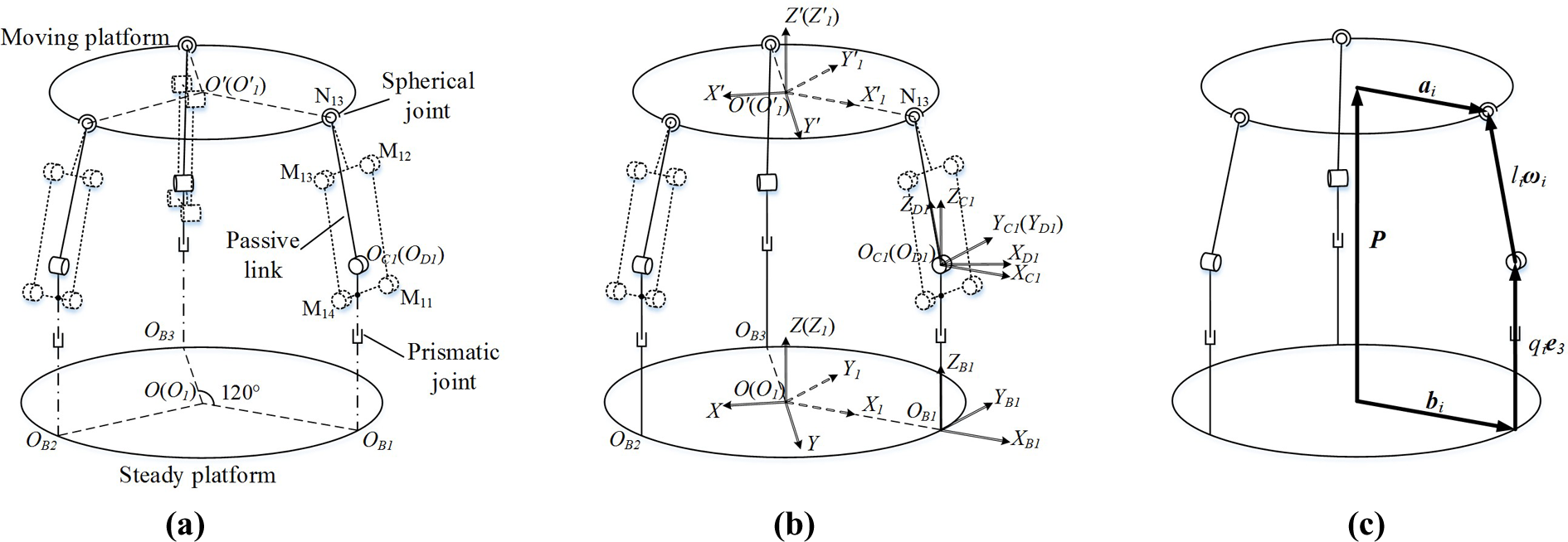
Error modeling process. (a) Structure of the 3-PRS mechanism simplified from the 3-P(Pa)S mechanism, (b) establishment of the coordinate frames, and (c) establishment of the vector loop.
The vector loops were established as shown in Figure 4(c). Taking one chain as an example,
Rotational matrices were defined to represent the orientation of coordinate frames.


in which,
The vector loop equation can be expressed as

where
Equation (3) is the kinematic model of the 3-PRS mechanism simplified from the 3-P(Pa)S mechanism. It can be expressed in a more compact format

Equation (4) describes the relationship between the pose of the end effector
When considering the structural errors, equation (3) can be expressed as

By subtracting equation (3) from equation (5) and considering

Multiplying both sides of equation (6) by

Letting

Equations (7) and (8) can be integrated into a matrix equation

where

in which


and


Thus, the error model of the 3-PRS mechanism is derived as expressed by equation (9), where
Structural errors of the 3-PRS mechanism simplified from 3-P(Pa)S mechanism.

Error projecting method
In this section, the structural errors of the parallelogram structure were projected to the 3-PRS mechanism. The schematic of the ith parallelogram structure is shown in Figure 5.

Schematic of the parallelogram structure.
The structural parameters of one PRS chain related to the parallelogram structure are shown by
Considering a certain circumstance in which the rotation angle of the parallelogram is φpi, the ideal vector loops between parallelogram structure and PRS chain can be established, expressed in equations (11) and (12)


Then, the structural errors can be regarded as the differential of structural parameters, so the vector loops including error were established, expressed in equations (13) and (14). In these two equations, there is an approximation that the orientation of the link di2 is parallel to the link li. The verification for the feasibility of this approximation is illustrated in the Appendix 1.


Vector loops expressed by equations (13) and (14) are illustrated in Figure 6, in which

Vector loops of the error projecting.
By subtracting equations (11) and (12) from equations (13) and (14), and ignoring high order infinitesimal errors, we obtain


Define an operator

where αi
is the angle between
Thus, equations (15) and (16) can be written as

in which

in which

where


Equation (18) is the error projecting function of parallelogram structures. In each chain, eight structural errors of the parallelogram structure were projected to two errors in PRS chain. Since the rest part of the 3-P(Pa)S and 3-PRS mechanisms are the same, the total number of structural errors of a P(Pa)S chain is 17, as shown in Table 2. And the total number of structural errors of the 3-P(Pa)S mechanism is 51. Additionally, the ideal values of the structural parameters in one chain are illustrated in Table 3, in which there are only displacement structural parameters since all the angular structural parameters are zero based on the establishment of the coordinate frames.
Structural errors in one chain of the 3-P(Pa)S mechanism.

Ideal structural parameters in one chain of the 3-P(Pa)S mechanism.

Thus, the whole error model of the 3-P(Pa)S mechanism is expressed by combining equations (4), (9), and (18) into an equation set. Compared to the general error model, this model includes the structure error of the parallelogram, so it can fully describe the errors of the 3-P(Pa)S mechanism. The error model has a lot of applications. For example, if the actuator movement
Verification of the error projection
Since the errors of the parallelogram structure were projected to the errors of the 3-PRS mechanism in the new error model, the error projection method needs to be verified. Thus, an experiment was carried out, in which two important structure errors of the parallelogram structure,

Experiment setup.

Flowchart of the experiment.
In the experiment, in order to generate structural errors
Then, three temperature sensors were placed along the width of the link that corresponding to
Next, the position error of the end effector was measured. A ball-ended measuring bar was installed on the end of the motor spindle to make sure the position error of the end effector can be measured along the three axes. Two Charge Coupled Device (CCD) non-contact laser displacement sensors (type: HK-020, Keyence Corp., Japan) were installed along the X-axis and Y-axis to measure the position error of these two axes. A dial indicator (type: 2109S, Mitutoyo Corp., Japan) was placed along the Z-axis to measure the position error of the Z-axis. The needle of the dial indicator and the laser of the CCD sensor are pointed to the center of the ball, so the slope of the spherical surface at the measurement point is zero, making sure that the spherical surface of the ball would not generate error in the measurement.
In the end, the measured error was compared to the error calculated by the error model. Owing to the symmetry of the three chains, only the first chain of the spindle head was analyzed in the verification experiment. The experiment was carried out at four different poses illustrated in Figure 9, in which the angle on the radius represents the tilt angle of the spindle head, and the angle on the circumference represents the orientation that the spindle head tilt to. At each pose, two structural errors, δd11 and δd12, were investigated, making the total number of experimental groups eight, as shown in Table 4. In the table, the pose of the end effector for each group was illustrated. Additionally, the investigated structural error (

Four poses of the mechanism in the verification.
Experiment groups.

The results of the verification were shown in Figure 10. The red columns indicate the measured absolute position error of the end effector, and the blue columns indicate the absolute position error of the end effector derived from the error model. Although the calculation of FEA would induce some error, the difference between the error by error model and measured error is small and the average residual error is less than 10 µm. So it can be concluded that the error projection method is reasonable and effective.

Results of the verification.
Sensitivity analysis
Sensitivity analysis is one of the most important applications based on the error model, which can derive the influences of the structural errors on the pose error of the end effector, contributing to the evaluation of the goodness of the mechanism as well as assisting the designing process. In this section, based on the error model proposed above, sensitivity analysis of the structural errors of the 3-P(Pa)S parallel type spindle head was carried out. Firstly, two basic indexes, LSI and GSI, were introduced.
LSI and GSI
The forward-problem of the error model can be expressed as

in which
And we can get
The position error


in which
Thus, the sensitivity of the jth structural error can be described as
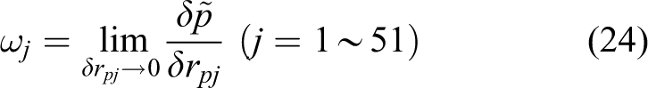
in which
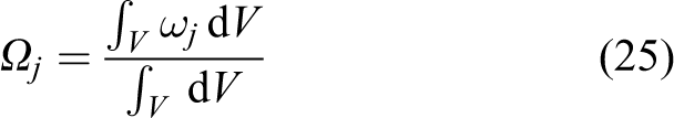
The GSIs of the structural errors are listed in Table 5.
List of GSIs of structural errors.
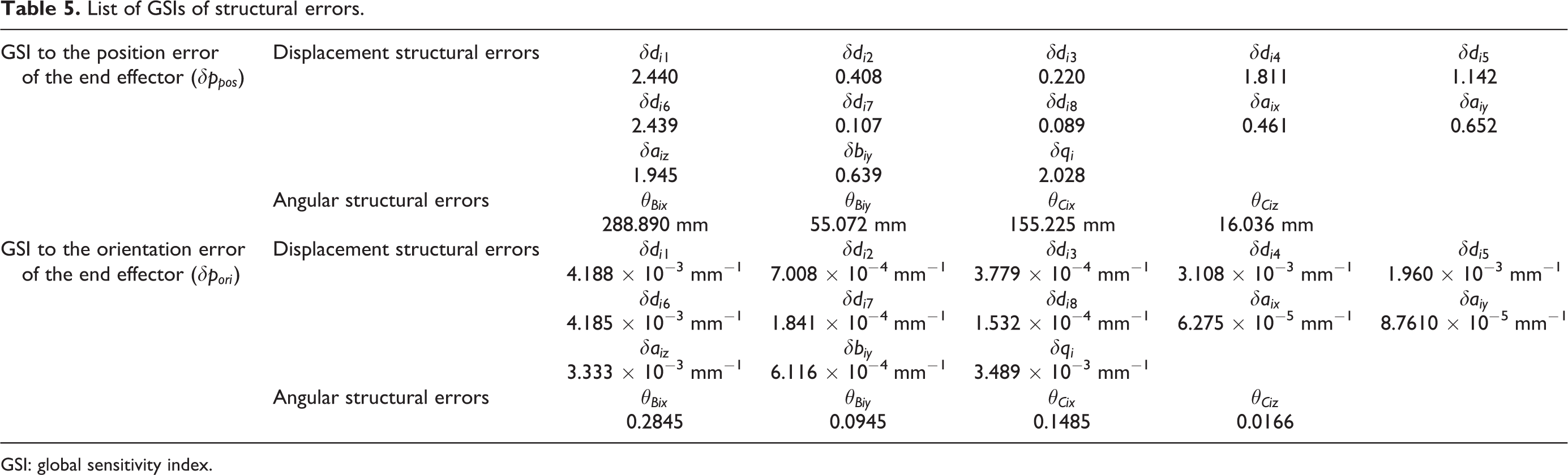
GSI: global sensitivity index.
SSLSI and SSGSI
LSI and GSI are the basic indexes for all kinds of mechanisms. However, based on LSI and GSI, it is preferred to propose a particular index that can better describe the characteristics of a specific mechanism such as the 3-P(Pa)S mechanism. The following factors need to be considered.
Firstly, although some errors have larger GSIs, their corresponding structural parameters are small. In manufacturing, the magnitude of the errors is usually proportional to the length of their corresponding structural parameters or positioning dimensions according to ISO-286, so the structural errors that have larger GSI or LSI may not have a large influence on the end effector in the real application. Secondly, it is noticed that GSI and LSI are all positive number, only reflecting the absolute extent of the influence. The new index is expected to have a sign (positive or negative), so we can figure out whether some structural parameters have similar or opposite influence on the end effector. Thirdly, in LSI and GSI, the error of the end effector is reflected by the position error and the orientation error. It is expected to establish a synthetic error that include both position error and orientation error, so the new index is more concise. Fourthly, the LSI and GSI of the displacement error and angular error don’t have the same unit to be compared together. It is expected that they have the same unit.
Therefore, the new index is established as follows.
Firstly, a synthetic error that reflects the error of the end effector is established. Only one chain was investigated as an example because of the symmetry. By analyzing the structure of the 3-P(Pa)S mechanism, it is mainly composed of three chains. For each chain, it can be regarded as a planer mechanism in the plane of the chain. Therefore, the structural errors of the chain can be classified into two categories: (1) structural errors within the plane of the chain and (2) structural errors perpendicular to the plane of the chain.
For the first kind of structural errors, these structural errors basically “increase” or “reduce” the length of the chain, inducing the error of the end effector by “rotating” the end effector in the plane of the chain (because the parasitic motion of this kind of mechanism is very small). Thus, we can project the error of the end effector to a unit vector

Projection of the position error and the orientation error of the end effector.
According to Figure 11, expressions of

in which βi is the angle between the plane of chain i and the X-axis


There are 13 of 17 structural errors (

The projection of orientation error of the end effector is expressed as

in which
Therefore, the synthetic error can be derived as

There are only 4 of 17 structural errors (

Therefore, the new local index of the jth structural error can be derived. For displacement structural errors, since the magnitude of the errors are usually proportional to their corresponding structural parameters, their corresponding structural parameters or positioning dimensions were introduced as a multiplier

in which
As for angular structural errors, it was firstly multiplied by the length of the corresponding part. So it can be transformed into the displacement structural error. Then, the index was multiplied by the positioning dimension corresponding to the transformed displacement structural error. For instance, the angular error of the guide way was multiplied by the length of the guide way to be transformed to the position error of the end of the guide way. Then, the index was multiplied by the positioning dimension of the end of the guide way. Therefore, the index can be written as
in which
Therefore, the new local index is established and named as SSLSI. The new global index can also be derived by integrating SSLSI within the whole workspace, V, named as SSGSI

Thus, the SSGSIs and SSLSIs of the structural errors can be derived. The SSGSIs of all the structural errors are listed in Table 6. According to the table, it can be observed that the SSGSI of displacement structural errors and the angular structural errors have the same unit to be compared together. Additionally, there is only one index for each structural error, making the new index more concise.
List of SSGSIs of the structural errors.a
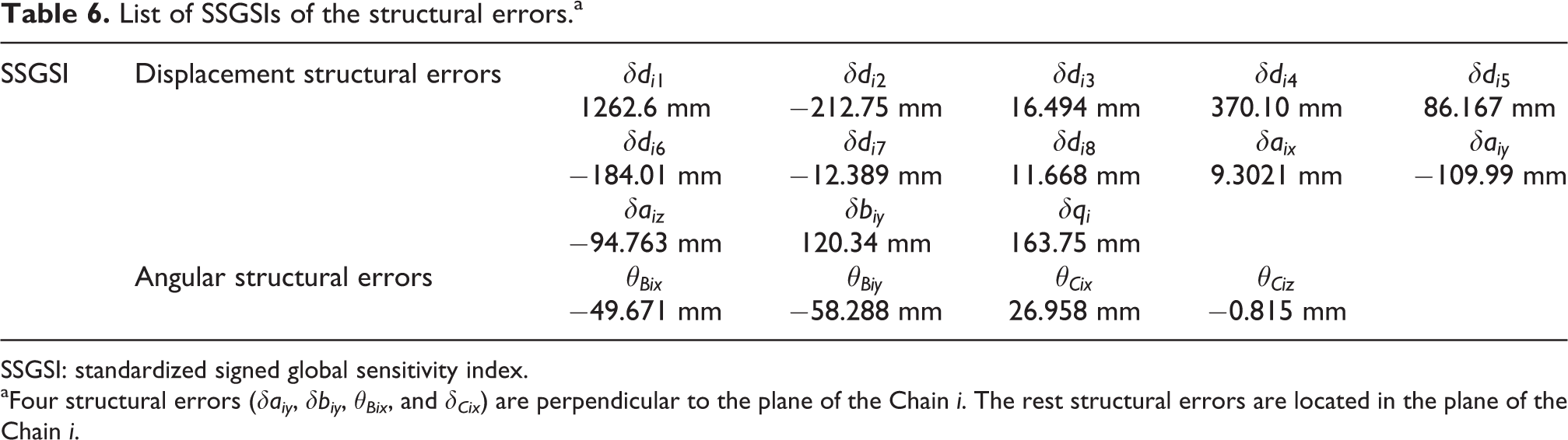
SSGSI: standardized signed global sensitivity index.
aFour structural errors (δaiy , δbiy , θBix , and δCix ) are perpendicular to the plane of the Chain i. The rest structural errors are located in the plane of the Chain i.
Since

SSLSI of (a) δd11, (b) δd12, (c) δd14, (d) δd16, (e) δq1, (f)
Analysis of the sensitivity index
Some conclusions can be drawn based on the SSGSIs and SSLSIs: Arrange all the structural errors according to their absolute SSGSIs, as shown in Figure 13. It can be concluded from the figure that, among all the 17 errors, the most influential ones are Since the relative error is usually considered during the machining, we should not only consider the magnitude of the error but also pay attention to the variation of the error. According to the SSLSI shown in Figure 12, it can be observed that most SSLSIs vary rapidly at the boundary of the workspace (where the tilt angle of the spindle head is larger). However, near the center of the workspace (where the tilt angle is smaller), the variation of the SSLSIs are slower. Therefore, this spindle head has a better performance near the center of the workspace where the influence of the structure errors varies a little. Additionally, since the standard deviation can reflect the extent of the variation of the data, the standard deviations of the SSLSIs of the structural errors were calculated, as shown in Table 7. According to the table, According to Figure 12, it can be further observed that some structural errors have similar contour of SSLSI but totally opposite sign (e.g.

Arrangement of structural errors according to their absolute SSGSIs (from the maximum to the minimum). SSGSI: standardized signed global sensitivity index.
Standard deviations of the SSLSIs.
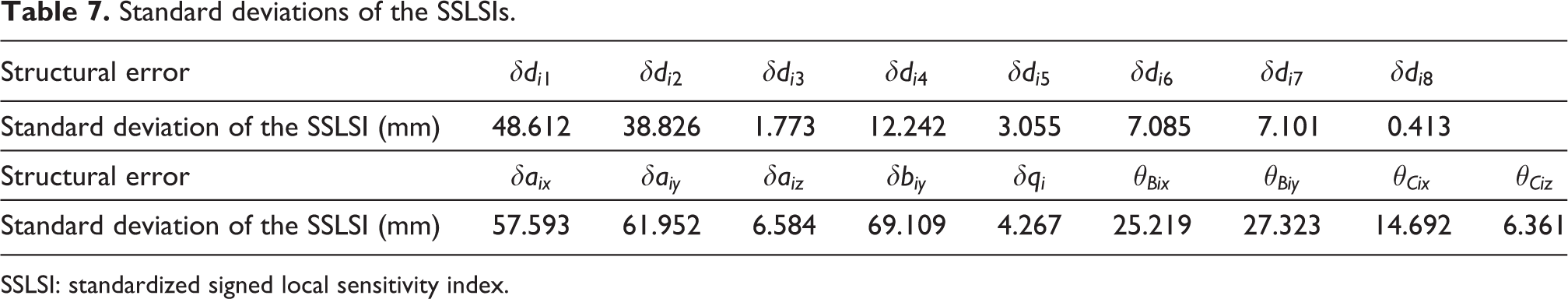
SSLSI: standardized signed local sensitivity index.
The above conclusions are expected to have further applications. The first possible application is the tolerance design of the part of the spindle head. Take δd11 and δd12 as an example. Generally, the ideal value of structural parameter is within its upper deviation and lower deviation. Additionally, since d11 and d12 have the same length and shape, the tolerance grade for d11 and d12 is the same, for example


Since the contour of SSLSIs for

Range of the absolute position error of the end effector at each pose within the workspace. (a) Before modifying the range of the tolerance and (b) after modifying the range of the tolerance.
However, since the ratio of the influence of


We can also derive that the approximate maximum absolute position error of the end effector would happen when d11 is equal to its upper bound and d12 is equal to its lower bound, or vice versa. And the minimum absolute error of the end effector is zero. So the range of the absolute position error of the end effector at each pose within the workspace can be derived as shown in Figure 14(b).
It can be derived that after the modification, the cost for manufacturing these two links can be reduced. Because the tolerance grade of d11 increases one level (IT5 to IT4, accuracy improved by 26%), but the tolerance grade of d12 can be reduced by two levels (IT5 to IT7, accuracy reduced by 133%). However, the range of the absolute position error of the end effector do not increase but become smaller according to Figure 14(a) and (b), which means that the accuracy becomes better.
The second possible application is to alleviate the error caused by the temperature change of the mechanism (e.g. the temperature change caused by the friction of the joints or the change of the environment). Since the links corresponding to
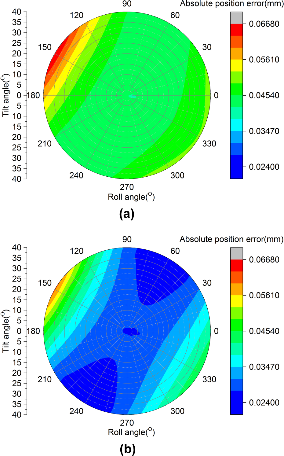
Absolute position error of the end effector before and after changing the material. (a) Before changing the material of the link and (b) after changing the material of the link.
According to the figure, it can be derived that the absolute position error of the end effector were greatly reduced within the workspace. The average position error in the whole workspace can be reduced from 0.0449 to 0.0309 mm. Especially for the near-center area (tilt angle within [0°, 20°]) where the spindle head mostly work at, the average error can be reduced from 0.0431 to 0.0285 mm, with the accuracy being improved by 33.9%.
Conclusions
The error model of a novel 3-DOF parallel spindle head based on 3-P(Pa)S mechanism was established. By projecting the structural errors of the parallelogram structure to the errors of the 3-PRS mechanism simplified from the 3-P(Pa)S mechanism, the errors of the parallelogram structure were considered into the error model. Then, the projecting method was verified by an experiment on the spindle head to prove its correctness.
Sensitivity analysis of the spindle head was carried out based on the proposed error model. According to the characteristic of the 3-P(Pa)S mechanism, two new sensitivity indexes, SSLSI and SSGSI, were proposed which can better reflect the influence of the structural errors to the end effector error.
By analyzing the SSLSIs and SSGSIs, structural errors that have the largest influence on the end effector were derived, and it is observed that the structural errors that have the larger influence are mainly located in the parallelogram structure. Additionally, the magnitude of the variation of SSLSIs within the workspace were also analyzed. Moreover, it was found that some structural errors have similar contour of SSLSI but totally opposite sign, indicating that they may have opposite influence on the end effector. Based on that, two possible applications to reduce the error of the end effector were proposed and simulated. The error projection method and the new sensitivity indexes proposed in this article are expected to be used in the error modeling and sensitivity analysis of other parallel mechanisms.
Footnotes
Declaration of conflicting interests
The author(s) declared no potential conflicts of interest with respect to the research, authorship, and/or publication of this article.
Funding
The author(s) disclosed receipt of the following financial support for the research, authorship, and/or publication of this article: This work was supported by the National Natural Science Foundation of China (no. 51757260), the National Science and Technology Major Project of China (no. 2015ZX04001002), and the Tsinghua University Initiative Scientific Research Program (no. 2014z22068).
Appendix 1
In the error projection, there is an approximation in which the orientation of one of the link (di1 or di2) of the parallelogram is parallel to li. Thus, we can use only one parameter, φpi, to describe the orientation of the parallelogram structure and the orientation of the link li, and the error model becomes simpler to solve.
It needs to verify whether this approximation would influence the accuracy of the model. There are two models (two cases) for this approximation: (1) di1 is parallel to the link li, di2 is not parallel to li; (2) di2 is parallel to the link li, di1 is not parallel to li. These two models are two extreme cases, and the real shape of the parallelogram is between these two cases, as shown in Figure 1A. So, if there is almost no difference between the outputs of these two models, it can be concluded that the approximation is feasible.
Therefore, we derived the error of the end effector at different poses of the spindle head derived by these two models, as shown in Table 1A. In the table, without loss of generality, three structural errors (
Thus, in this article, model 2 was selected, so di2 is parallel to the link li
. And the orientation of di2 can be described by φpi
in the local coordinate frame of the parallelogram structure, {xi
, yi
}. Therefore, there is no orientation error,