
Abstract
This article analyses and mathematically describes a method for mutual identification of multiple mobile robots. The method interchanges identification numbers among multiple robots via audible beeps multiplexed by frequency. The identification sound is sent only when robots approach to each other. The algorithm was primary designed for e-puck robots, but it can be used in any multi-agent robotic system; each mobile robot has to be equipped with three microphones for determination of the sound’s direction, speaker and signal processing microcontroller.
Introduction
Multi-agent systems contain multiple autonomous agents which have to cooperate and communicate with each other. In the special case of the multi-agent mobile robotic system, the constellation (mutual position) of the agents (robots) changes constantly. In order to control interaction between two robots near to each other, it is necessary to create a communication channel between them. Such connection link requires that each robot is able to identify which one is the robot next to it. This is similar to communication between two persons in a crowd of many other persons – first the recipient of the message has to be identified and then every message is addressed directly to him/her. People usually identify each other by their visual look. However, such approach cannot be used in a homogeneous multi-robot system because all robots are visually identical. We will attempt to review some of the more relevant approaches to robot identification in the e-puck domain in this section. The first distinction that it is necessary to draw is that between centralized, ambient and local identification and communication systems.
Centralized approaches
By a centralized system, we mean a system, in which one or more functions are performed by a central entity (e.g. a centralized communication system). Among centralized approaches directed at e-pucks, we may include an approach mentioned in literature
1
–3
, which uses an overhead camera, processes the image and sends the resulting information to all e-pucks. This requires
Main drawback of the centralized approach is its poor flexibility, because it requires installation of additional components (camera) into the environment and poor scalability, since increasing the operating area results in increasing of the overall system cost (more cameras have to be installed, centralized processing unit has to be more powerful, etc.).
Ambient approaches
By an ambient system, we mean a system, which relies on the environment for some of its functionality – that is, it requires that the environment be enhanced with several pieces of special external equipment. It is possible to use radio frequency identification (RFID), which have been applied in the robotics domain. RFID tags can be used to establish an intelligent environment
Mentioned approaches are difficult to implement into e-puck robotic platform, because existing hardware does not provide sufficient functionality. Apart from the e-puck platform, the RFID communication may be sensitive to the EMI (especially in harsh industrial environments).
Local approaches
By a local system, we mean a system, which is fully decentralized and does not rely on any special external equipment. Local infrared (IR) communication: One of the most popular approaches to local communication among e-pucks takes the form of the libIrcom library
6
, which allows communication using the infrared sensors available on the e-pucks. The local communication system thus established is multiplexed with the standard proximity sensing system, which also relies on the sensors. The library allows communication at the rate of up to 30 bytes per second from sender to receiver and also incorporates a CRC check.
7
The communication distance may be up to 25 cm.
6
Local visual identification: There have also been some approaches that have attempted local visual identification. While this is a viable alternative in general, it is not easy to implement in e-pucks, due to their severely limited computational resources. There is also the additional complication of e-pucks being homogeneous and thus not easily distinguishable. There have nevertheless been a number of experiments, which attempted this, with varying degrees of success. A popular approach is to use LEDs to colour code the e-pucks and then use the omnidirectional camera turret to distinguish them by the colors
8,9
Acoustic localization: Perhaps, the most relevant family of approaches (with regard to the topic of the present work) is that which uses acoustic methods to accomplish identification and localization. In this strain, Dellaert et al.
10
present Marco Polo localization, which is an acoustic method of measuring the distances to other robots by listening to the sounds they emit and measuring the time the signal takes to travel. Each individual robot also used odometry to record its own change of position. An important limitation of the results is that all the microphones were wired into a single computer, thus working around the problem of synchronization. Dellaert et al.
11
also use audible acoustic signals, but in addition to measuring the distance, it is also able to estimate the bearing angles. To this end, it uses stereo microphones. Synchronization of robot clocks is achieved using a pair of sound measurements between the robots. Becker and Risler
12
also introduce an acoustic system, which enables mutual localization in a team of robots. The authors use an acoustic variant of code division multiple access (CDMA): Every robot is assigned a specific signal pattern and then cross-correlation is used to tell the robots apart. Similar to the study by Lin et al.,
11
the system also uses stereo microphones to estimate the bearings. The acoustic signals are supposed to be sent out at regular intervals, which the method utilizes to perform synchronization. There are also a number of methods, which make use of inaudible frequencies. Mao et al.
13
list several methods based on ultrasound, for an instance. There are also some ambient approaches, such as that described by Ogiso et al.
14
, which makes use of acoustic beacons positioned at known locations in the environment. Such approach requires additional infrastructural changes like other ambient methods and lacks the flexibility of the local solution.
The proposed method
Our proposed method utilizes identification by sound. Each robot is equipped with a speaker (for sending own identification (ID)) and a microphone (for receiving ID of the other robots); therefore, no additional hardware is required. In order to allow multiple robots to communicate at the same time, we have assigned a unique audible frequency to each robot. Such approach suppresses the effects of the environmental noise. Selection of suitable frequencies will be discussed in the next section. As a testing platform, we have used educational robots called e-pucks 15 , which contain a small speaker and three microphones (one of the microphones is below the speaker). Multiple microphones allow us to determine the direction from which the sound is coming (a microphone array is capable of determining the position of multiple moving objects as described by Burgard. 16 ). The e-puck robot (see Figure 1) is a suitable platform for research of multi-agent mobile systems and inter-robot communication. Its greatest disadvantage is lower computational power and operational memory of the used microcontroller which does not allow us to implement more advanced navigational and control algorithms directly inside the microcontroller. E-puck robots use wireless Bluetooth 2.0 communication which does not provide sufficient transfer speed (set to 12 kB/s by hardware) to transfer readings from all three microphones in real time. Therefore, the sound identification algorithm has to be implemented onboard and the efficiency of the algorithm has to be taken into account. Usage of different frequencies (an analogy of the frequency division multiplexing) for each robot avoids the need for precise synchronization. Compared to the above-mentioned methods (RFID, IR, visual identification), the proposed method is resistant to EMI, strong thermal irradiation or changes in the ambient light.

The e-puck robot.
Selection of ID frequencies
Selecting the proper frequencies for identification of the robots is the most important task of the proposed method. Since each robot inside a robotic swarm (consisting of robots) has its own ID frequency, we have to choose different frequencies. Each e-puck robot samples the voltage of its microphones at the sampling frequency and then analyses the received sound by frequency analysis (discrete Fourier transform, DFT), which computes amplitudes of the selected frequencies. ID frequencies have to be aligned with the frequencies detected by DFT. Figure 2 illustrates the false spread of the spectrum if the frequencies are not aligned. Such spread could cause false-positive detection of ID frequency.

Spread of DFT spectrum due to the wrong choice of the ID frequency (FID = 3000 Hz, Fmic = 16,384 Hz, Nmic = 128 samples). DFT: discrete Fourier transform.
The DFT frequencies are given by the following
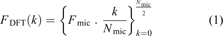
where k is an index in the DFT output array and Nmic is the count of samples processed by DFT. After this constraint, the count of available discrete frequencies is Nmic/2. Another constraint is the bandwidth of the system audio codec–speaker–air–microphone. The e-puck robot is using codec Si3000 manufactured by Silicon Labs, 17 which works as a digital to analogue converter with an internal low-pass Finite Impulse Response (FIR) filter. The played sound is sampled at frequency Fs = 9600 Hz (a change in the basic e-puck codec driver is required because it uses only 7200 Hz sampling). The frequency response (measured by a standard PC microphone) of the e-puck’s speaker is shown in Figure 3.

Frequency response of the speaker mounted on the e-puck.
The rapid fall of the amplitude around 4300 Hz is caused by the FIR filter implemented in the codec. The cut-off frequency of the filter is 17

Therefore, the maximal ID frequency has to be smaller than Fmax. The maximal DFT index is then

The air attenuates higher frequencies (f > 4000 Hz) more than lower frequencies. If the robots are next to each other, this effect is negligible. On the other hand, the piezoelectric microphones mounted on the e-puck robot (3× SPM0208) are more sensitive to higher frequencies (see Figure 4).

Frequency response of the microphones mounted on the e-puck. 18
If we combine the speaker and the microphone, the theoretical resultant sensitivity rapidly increases with frequency. Therefore, it is more efficient to use frequencies above Fmin = 2000 Hz. Corresponding lower bound of the DFT index k is then

Due to the non-linearity of the whole audio system also higher-order harmonic frequencies will be detected. The best way to avoid false-positive detection of the ID sound is not to use lower frequencies which are divisors of already used frequencies. An algorithm which selects as much unique non-divisible frequencies from the DFT vector as possible can be described by the following algorithm (see Figure 5). Result of the algorithm is a vector of indices k, which defines ID frequencies from DFT frequency series (1).

Algorithm for selection of ID frequencies.
If the count of chosen indexes is smaller than the count of all robots, we have to increase the count of microphone samples Nmic. Table 1 shows computed ID frequencies for 10 e-puck robots.
Selected ID frequencies for 10 e-puck robots

DFT: discrete Fourier transform.
Determining the direction of the sound
A single microphone is only capable of determining the ‘presence’ of other robots with different IDs. If the precise frequency response of the whole audio system were known, it would be theoretically possible to also determine the distance to each neighbouring robot. If three or more microphones are available, we are able to determine the direction to the neighbour. We assume that the robot’s speaker is a point source of sound with homogeneous horizontal directional characteristics. All vectors between the microphones and the speaker are shown in Figure 6. If we bind the origin of the coordinate system with the robot’s chassis, vectors r1, r2 and r3 are constant.

Distances between microphones and speaker.
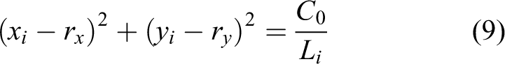
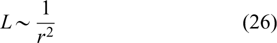
If we neglect attenuation of the sound caused by absorption in air, the intensity of the sound of the i th microphone Li is equal to

where C0 is proportional to the output acoustic power of the speaker and di is the distance from the source to the microphone. According to Figure 6, the following holds

The Cartesian coordinates of the vectors are


Then the length of the vector di is (with respect to equation (5))
If we transform vector r into polar coordinates, we obtain
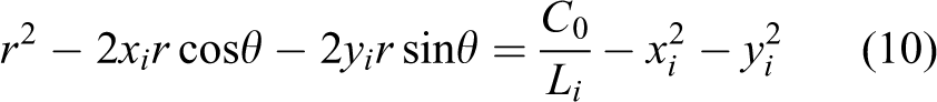
where θ is the directional angle to the detected neighbour. If we use substitution


equations for all three microphones can be written in the following matrix form

Please note that the matrix of the system is constant and invertible; therefore, it is valid to write

where

E-puck microphones are placed in the following pattern (top view in Figure 7). If we put the centre of the coordinate system between microphones 1 and 2, equation (16) will simplify to
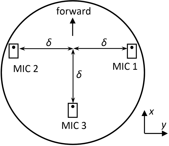
Microphone placement on the e-puck robot (δ = 31 mm).

Reverting the substitution (11)–(13) will result in


According to equation (20), it is possible to determine θ from local sound intensities Li without knowing the actual acoustic power C0 of the source speaker. In general, it is possible only if the origin of the coordinate system is placed to the centre of the circle passing through all three microphones.
Sound intensity is proportional to the square of the amplitude

The amplitude Ai of each ID frequency can be computed from raw data by the Goertzel DFT algorithm 19 . This algorithm is especially suitable for this task since it computes the amplitude of only one selected frequency (we do not need to evaluate other frequencies than the selected ones). The algorithm also works with real numbers (instead of the FFT algorithm which requires complex algebra) and might be running in the real-time (incremental) mode.
Implementation of the method into the e-puck robot
Since the detection of neighbours is supposed to run in real time and the onboard computational power is limited, we have to optimize the algorithm for specific hardware used by the e-puck robot. The relevant characteristics of the robot’s main signal processor are 16-bit wide data bus, 8 kB RAM memory, and DSP fixed-point core with 40-bit accumulator. The digital signal processing core (DSP) of the processor provides single-cycle multiply-and-accumulate and bit shifting instructions with 16-bit fixed-point numbers (in format 1.15 bit). Our aim is to optimize the well-known Goertzel DFT algorithm for the given CPU.
The Goertzel algorithm can be in short described by the following two stages
19
: Stage 1: incrementally compute real state variable s[n] for each microphone sample x[n]

Stage 2: compute complex frequency response Ȧ

According to equation (23), it is required to remember only the past two values of the state variable. Formulas (19) and (20) take, as a parameter, the sound intensity L which is equal to

where

Since fixed-point arithmetic is being used, there is a possibility of data-type overflow. Sound intensity at a given ID frequency decreases by square of the distance between the microphone and the source speaker
which causes great dynamic range of the input signal. Commonly used technique for handling variability of the signal power (e.g. in DTMF detection 20 ) is initial power normalization. Each sample is scaled down by following

Such normalization only ensures that the overall signal power is unite. The power of each spectral component can be higher, especially in the case when the signal contains two close frequencies f1,f2 with amplitudes A1, A2, respectively. Figure 8 shows the power spectrum of the sound received during simultaneous transmission of both ID sounds (own and foreign). If we scale the input signal according to equation (27), the foreign ID spectral component would be suppressed and the overall system sensitivity would be decreased. If no valid ID signal is present, the adaptive scaling of the whole signal would increase the power of noise. The overflow might occur also during computing the state s[n] even if the resultant sound intensity has not overflowed (e.g. when the signal has a significant low-frequency component).

Overflow of data type during transmission of own ID sound.
In order to avoid overflow problems, we have modified the Goertzel algorithm. The modification utilizes prevention of overflow in each step of the algorithm and adaptive scaling of the intermediate state s[n]. If the value stored in the internal dsPIC accumulator requires more than 32 data bits (including the sign bit), the overflow flag is automatically set. Since the accumulator is 40 bits wide, this behaviour allows us to avoid overflow (by scaling all the following values of x,s, sp down by shifting) before it actually occurs. The flow chart of the modified algorithm is shown in Figure 9.

Flowchart of the modified Goertzel algorithm.
Assembly instructions of the dsPIC processor are displayed in curly brackets; multiplication and division by two is implemented as shifts. The overall algorithm requirements are (including nondisplayed stack handling and core configuration)
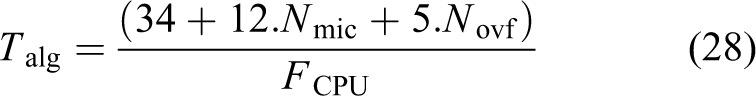
where Novf is the count of overflows that occurred during the run of the algorithm (usually between 0 and 4) and FCPU is the core clocking frequency (14.7456 MHz). The algorithm is evaluated for all IDs and all three microphones. In order to remove noise, the resultant amplitude is an arithmetic average of multiple algorithm steps. One step of full detection should take approximately 100 ms (we have averaged 16 iterations of the algorithm with all three microphones for all 10 selected IDs). Each iteration is processing new set of samples from microphones. Our algorithm takes 10 ms per one robot in the swarm. If there are multiple robots in the swarm, the computational load increases proportionally. The real response time is much larger depending on the current CPU load. Due to the lower sensitivity of the whole system (which is required in order to prevent false-positive detection of a neighbouring robot), the ID sound must have an appropriate intensity which makes it uncomfortable for humans. Therefore, it should not be transmitted constantly. Since the e-puck robot is equipped with eight IR proximity sensors, it is possible to detect the presence of a near object (up to approximately 10 cm). If any close object is detected inside the predefined area, the robot will beep its ID sound for 1000 ms. Each IR sensor is evaluated separately and the ID sound is transmitted every time the mutual position of two or more robots changes (e.g. by circling of one robot around another one). The length of beep should be much higher than execution time of the optimized algorithm (1000 ms >> 100 ms) which ensures that the ID sound is processed multiple times by each robot.
Experiments and results
The above-mentioned algorithm is based on dependency between intensity of the sound and the distance to the source. In case of two e-puck robots, the characteristics are shown in Figure 10. Data were measured with the sound of frequency 4032 Hz, the robots were aligned along one axis, and the active robot was rolling by a fixed number of steps. In our experiments, we have used only two robots because, according to the Figure 8, each ID frequency is detected as a single line in the frequency spectrum; therefore, ID frequencies selected according to the chapter II are mutually independent.

Function between intensity of the sound and distance from the speaker.
Other detectors are invoked only by an external noise intensity of which is below 10% of the intensity of the valid ID signals (see Figure 11). These low-level intensities are not taken into account because the ID is valid only if it exceeds marked threshold (500 Least Significant Bit (LSB)).

Spectrum of three different ID sounds (ID = 7, 8 and 9) played simultaneously from three e-puck robots with the same distance from the microphone.
As can be seen, the measurement contains a significant portion of noise and the measured characteristic is not smooth; therefore, we cannot expect high precision (in order of degrees) of the direction estimation (see equation (20)). The turret (an extension board for the e-puck on which the speaker is mounted) deforms frequency response of the acoustic system because it forms a resonant cavity under it. Figure 12 shows how the ID sounds are detected by transmitting and receiving e-pucks (detected by microphone 2, placed under the speaker). The active robot consequently transmits all ID frequencies and detects them with overflow (reached maximal signed 16-bit intensity as expected). The passive (receiving) robot detects much lower intensity of the sound (approximately 10 times lower at the distance 100 mm between the centres of the e-pucks). Since the frequency response is deformed by the turret, the estimation of the direction is only approximate.

Comparison between detected sound intensity by the active (beeping) e-puck robot and the passive (listening) robot (each bar represents one ID frequency, note the different scale of the vertical axes).
Figure 13 shows detection characteristics of the direction. In the experiment, we used two e-puck robots: the passive one was steady and the active one circled around the passive one with the constant radius r = 90.

Resultant characteristics of the detection.
As can be seen, the system of microphones mounted on the e-puck can be used only for very rough estimation of the direction from which the ID sound comes. This is caused mainly by the nonuniform sensitivity of the algorithm. Theoretical intensity of the sound measured by the i th microphone is equal to (see equation (9))

The sensitivity of the sound intensity measured by i th sensor to the direction θ is equal to

The overall error of the computed direction is (considering the error distribution to be Gaussian)

where ΔL is the standard deviation of the measured sound intensity (equal for all microphones). The overall sensitivity of the algorithm (response of the sensors to the change of the direction) can be expressed as follows

If we visualize the formula (32) using (30), the resultant low sensitivity in Figure 14 around 0°, ±90° and ±180° reflects dead bands in characteristics in Figure 13.

The sensitivity of the algorithm.
Since the hardware of the e-puck robot has limited capabilities, only few methods have been developed directly for this platform. The results achieved by our method can be compared with the IR mutual localization method. 7 The comparison of the precision is shown in Table 2:
Comparison of the proposed method with IR localization.

As can be seen, the error of the bearing (direction θ) of our method is higher than the error of the IR localization. It is caused mainly by low number of the used sensors (12 IR vs 3 microphones), which results in low sensitivity in certain directions. On the other hand, the error of the estimated distance r (see equation (19)) is slightly smaller if our method is used and the system is precisely calibrated.
As we can see in the publications 21,22 , the issues of the multimodal data fusion are very actual. Many researchers use multimodal data fusion in their work. Multimodal data fusion helped, for example, with motion 23 , object 24 recognizing or with localization of mobile robot 25 . In our case, we may combine our proposed sound localization method with the IR localization method using simple complementary filter, which will improve the overall precision of the localization.
Conclusion
This article has explained a possible solution for mutual identification of multiple mobile robots. As an experimental platform, the education robot called e-puck has been used. The proposed algorithm selects appropriate frequencies for ID sounds considering the acoustic characteristics of the system driver–speaker–microphone. Due to their constraints, all frequencies had to be selected from the audible spectrum. An appropriate selection avoids false detection of another ID and optimizes overall system performance. Data processing algorithms were optimized for the dsPIC30 processor incorporated inside the e-puck. In order to avoid overflows and maintain the performance, it was necessary to modify the Goertzel algorithm used for the detection of ID frequencies from microphone readings. Since the microphones used inside the e-puck robot have low sensitivity and the construction of the robot deforms the flow of acoustic waves, the robot is capable only of roughly determining the direction from which the ID sound is coming. In order to improve the sensitivity of the system, it is necessary to use multiple microphones mounted outside the robot.
Main advantage of the proposed method is its simplicity; thus, it can be implemented into low-cost hardware. It does not require synchronization of time among robots, and each robot should only have same and stable CPU frequency which is easy to achieve by a crystal oscillator. The proposed method for mutual identification and localization is also resistant to the electromagnetic interference which makes it a good replacement for applications where high level of EMI does not allow to use RFID principle. In particular, in the case of e-puck robots which are equipped with limited hardware, the method provides a suitable solution for mutual identification of two autonomous robots that met in an unknown environment. After the ID of the opponent robot is obtained by our method, the e-puck robot can connect wirelessly to the Bluetooth module of the opponent (peer-to-peer communication); therefore, our method eliminates the need for some central communication authority in larger swarm of e-puck robots. Those robots that are not nearby are not considered; therefore, the overall load of the communication is much smaller (every agent does not need to communicate with all other agents).
Footnotes
Declaration of conflicting interests
The author(s) declared no potential conflict of interest with respect to the research, authorship, and/or publication of this article.
Funding
The author(s) disclosed receipt of the following financial support for the research, authorship, and/or publication of this article: This work was supported by Slovak Research and Development Agency under the project no APVV-15-0441.