
Abstract
The objective of the autonomous navigation aims to achieve the self-motion control for a robot with the environmental feedbacks and becomes popular recently. Problems of complex modeling, large amount of calculation, and lacking of environmental information always exist in autonomous navigation methods. This article proposes a self-navigation method with a fuzzy three-dimensional grid depicted by dual two-dimensional grid maps. Meanwhile, a synthetic preprocess is presented to perform localization through switching among the weighted three-point localization method, the two-point localization method, and the weighted average localization method. For reducing the amount of calculation, an improved fuzzy three-dimensional grid mapping method where the three-dimensional map is described by dual two-dimensional grid maps, the identifier map, and the height map is designed. Especially, the static and dynamic information within the map are divided and updated fuzzily. The global path planning is performed with the static information, and the real-time obstacle avoidance is conducted with the dynamic information. The results of simulations and experiments demonstrate that the proposed method has better properties in efficiency of navigation and lower amount of calculation than the competing methods.
Introduction
Nowadays, intelligent robot application areas expand into every walk of life such as the biped robots, 1 –3 unmanned aerial vehicles, 4 –6 mobile robots, 7 and so on. Among them, the researches on mobile robots always play an important role complying with their better stability. 7 Along with the development of mobile robots, researches on self-navigation of the mobile robots have attracted many scholars’ interests. Generally speaking, the autonomous navigation process usually performs three main tasks, localization, mapping, and navigation, and every task plays an important role to the others. 8
In earlier times, some navigation methods, such as potential field methods, 9,10 topological navigation, 11,12 and so on, are applied frequently. Through these methods, a robot can achieve self-navigation easily, whereas these methods may have some shortcomings. For instance, in potential field method, the singular point may cause the robot to stop at a certain position, and the robot may show decision jitter problem under complex environment. For the more flexible navigation, the adaptive finite state machine (AFSM) integrating the artificial neural network (ANN) classifier with the traditional FSM is applied. 8,13 Through the ANN, a robot can be trained/adapted to recognize a complex set of state changes. Then, the AFSM allows the mobile robot to autonomously follow a sequence of states/behaviors to reach the destination. However, training data may not be easily obtained and its covering domain may also be the limitation of the method. Facing the problem of large requirement for training data, reinforcement learning is used in some navigation methods. 14,15 A mobile robot can choose the action with the largest value in a state through updating the values of the Q-table. By reinforcement learning, a mobile robot is able to perform self-learning and self-adapting continuously and to implement the dynamic autonomous navigation under an unknown environment perfectly. The outstanding navigation performance may need a great amount of learning under various scenes, which may be a huge cost on time and energy.
In addition to above-mentioned methods, vision-based navigation is also a hot research direction. Single vision-based navigation is introduced in some works. 16,17 Feature extraction is executed for recognizing the identification markers. Then, the localization and the autonomous navigation are conducted according to the recognized information. Vision-based navigation combined with other sensors such as laser is also designed. 18,19 The visual identity is used for scene recognition and marker searching. Meanwhile, sensors are used for capturing the depth information for real-time obstacle avoidance. Vision-based methods have high practicality and flexibility in the complex environments. However, the obtained environmental images change along with the motion of a robot, which may not only result in a complex navigation model but also may have high requirements for the camera’s calibration model and kinematics model.
Contrast to vision-based navigation, grid map-based navigation methods achieve the self-navigation while reducing the resources cost and promoting the running efficiency and speed. 20,21 In general, grid maps can be divided into two-dimensional (2-D) and three-dimensional (3-D) gird maps. Whereas, traditional 2-D gird map may lack the 3-D environmental information and may make the information about the traversable area be over cut during navigation. In 3-D grid map, there may be more resource consumption compared with 2-D grid.
Complying with the more simple structure and lower resource cost the grid map-based methods have compared to other methods, this article proposed a fuzzy 3-D navigation method (FTGNM). For accurate localization, a synthetic localization approach (SLA) is proposed where a switcher is designed among three proposed localization methods: the weighted three-point localization method (WTPLM), the two-point localization method (Two-PLM), and the weighted average localization method (WALM). Inspired from grid maps, a fuzzy 3-D grid map, described by dual 2-D grid maps, the identifier map, and the height map, is proposed. Especially, the states of objects in the grid map are divided and updated by fuzzy logic. Finally, according to the distribution of static and dynamic objects, the holonomic navigation is constructed, where the global path planning can be executed by the static information, and real-time obstacle avoidance can be performed by the dynamic information. The overall navigation method architecture is improved, resulting in the proposition of this new navigation method architecture. The sections of this article are organized as follows. “Synthetic localization approach” section presents the SLA with switching among three localization methods. The fuzzy 3-D grid mapping method (FTGMM), where dual 2-D grid maps depict a 3-D grid map, is presented in “Fuzzy 3-D grid mapping method” section. The holonomic autonomous navigation logic is given in “Autonomous navigation method” section. “Simulations and experiments” section presents the experimental results obtained on the simulation platform and the real mobile robot to illustrate the performance of the proposed method. The last section presents the conclusions.
Synthetic localization approach
Mobile robots can receive the infrared signals from the sources through the infrared sensors. Then, the distances between the robot and the signal sources can be obtained with the infrared phase ranging method, 22 and the robot’s global position can be calculated through these distances. Considering the number of sensed signal sources is different, an SLA is proposed by switching among three designed localization methods which correspond to different situations. The WTPLM is executed when the robot receives three and more than three source signals. The Two-PLM is utilized within two source signals. And the WALM is conducted when there is only one received source signal.
Especially, while the real-time coordinate of a mobile robot is calculated by the three methods continuously, the last five historic coordinates are recorded continuously as {(xi , yi )|i = 1,2,...,5}, where (x 1, y 1) is the newest coordinate and (x 5, y 5) is the oldest coordinate. In initialization phase, the five coordinates are set to the start coordinate of a robot.
Weighted three-point localization method
When the number of sensed signal sources is three or more than three, the WTPLM is proposed according to the horizontal distances between a mobile robot and sensed signal sources. The specific steps of WTPLM are as follows:
Step 1: Assuming sensed signal sources is
Step 2: Considering the signal decay, larger distance between a signal source and a robot is, less reliable the localization result is. The average distance
Step 3: Repeat step 2, and the average distances
Step 4: The mobile robot’s final weighted coordinate (xm
, ym
) can be calculated by


In particular, calculation process of the robot’s coordinate under the combination of one three signal sources is as follows.
As shown in Figure 1, ∑


Three points localization method diagram.
Equation (4) can be transformed into

where
Two points localization method
When the number of sensed signal sources is two, the Two-PLM is conducted. The coordinates of the two signal sources A and B are (xA , yA ) and (xB , yB ), respectively, and the feedback horizontal distances are lA and lB . Similar to Figure 1, the mobile robot is located at the intersection of two circles whose center is A or B and radius is lA and lB , respectively. Hence

In general, two solutions (x m1, y m1) and (x m2, y m2) can be obtained by solving equation (6), and one of the solutions must be the real coordinate of the robot.
According to the weighted least square method, T 1 and T 2 can be calculated by

Therefore, the real coordinate of the robot (xm , ym ) is (xmi , ymi ) with the smallest value between T 1 and T 2 with

Weighted average localization method
If the arrangement of the signal sources is unreasonable, the situation may be appear that the number of received signal is only one or zero. If the number is zero, the mobile robot will stop and send out a warning. If the number is one, this situation should be last for a very short time and the general guidance should be rendered. Therefore, a WALM is presented in this article.
According to the historic coordinates {(xi , yi )|i = 1, 2,..., 5}, the approximate moving trajectory of the robot could be obtained by line or curve-fitting methods. Five points limit the power of the fitting polynomial to less than 5. Consequently, there will be four fitting polynomial models

The five historic coordinates are substituted into the four fitting functions, and the matrix representations are

Then, equation (10) can be transformed into

Assuming


Through this way, the robot could conduct a general motion guidance in signal source situation. This situation may appear in a very short time and a certain range of error could be tolerated. The efficiency of the navigation is mainly related to the WTPLM and Two-PLM. What’s more, this situation should be avoided by increasing the number of signal sources as possible.
Fuzzy 3-D grid mapping method
For researches on mapping, the map projection method and 3-D map method become recently popular. Whereas, the map projection 20 may forsake the height information of the objects, which may be not suitable in some scenes. For instance, chairs and tables are regarded as unpassable with the map projection method, while they may be passable for mobile robot. The 3-D mapping methods such as the 3-D grid construction method 21 and the vision-based 3-D reconstruction method 23 may have a little large amount of calculation which may not satisfy the requirement of the hard real-time property of the embed robot system. Meanwhile, the 3-D-based mapping algorithms may be a little complex. Consequently, in order to obtain enough 3-D information while ensuring the low amount of calculation, this article proposes an FTGMM for mapping. In the map information storage part of FTGMM, an improved 3-D grid map is put forward which has dual 2-D grid maps: one is for identification makers and the other is for height information. In the map information updating part of FTGMM, the states of objects are divided into static or dynamic state through the fuzzy division method.
Improved 3-D grid map
First of all, the size of each mesh of the grid map should be determined, which can affect the calculation amount of searching in the grid map. Generally speaking, the size of each mesh could be set as the same size of the robot. The signal sources and target point should be set in the grid map in the initialization phase. Some particular obstacles could also be preset in the grid map such as the wall and so on.
Then, the grid map can be reconstructed and updated during the motion of a robot. For instance, as shown in Figure 2, Figure 2(a) is the identifier map and Figure 2(b) is the corresponding height map. The sensed obstacles and signal sources are set as different ID numbers in identifier map. In Figure 2(a), the red meshes are the signal sources and the ID numbers such as −1, 5, and 8 are the sensed obstacles. By the sensors of a robot, such as the laser and sonars, the height and size of an obstacle can be obtained. Especially, the height state of obstacles can be suspending, for example, chairs, and complete covering, for example, boxes, and when the obstacle is suspending high enough, the robot is able to pass through. The article uses negative value to represent the suspension height and positive value to stand for the height above ground, and zero or null means there is no obstacle, as shown in Figure 2(b). If the robot cannot perceive the height of complete covering objects, which means the height of objects is large, such as the wall, the height can be given a relative large value.
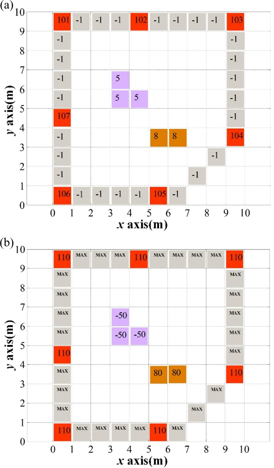
Improved 3-D gird map diagram. (a) Identifier grid map. (b) Height information grid map.
Map updating with fuzzy logic
Along with the motion of a robot, the 3-D grid map should be updated real timely. In traditional mapping methods, the state of objects is the same, such as in Lin et al., 20 Lau et al.,21 and Endres et al., 23 and they are all regarded as obstacles. Considering conducting the path planning according to all the objects information is a little complex, in this article, the states of objects are divided into two parts: the static objects and the dynamic objects. The static objects are a position set of objects which do not move within a certain time, and the dynamic objects are a position set of moving objects. Then, the navigation method can be performed according to the static and dynamic information. Especially, objects’ state may change between the dynamic and the static, and there is no clear boundary between the two states, which is to say that it is a fuzzy concept. Therefore, this article makes use of the fuzzy logic 7,24,25 to divide the objects’ states and update the map of the scene real timely.
Fuzzy judgment for two objects’ relationship
As shown in Figure 3, the

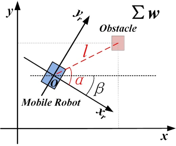
Relative position diagram of a mobile robot and an obstacle.
Assuming the global coordinate of the robot is (xm , ym ), the global coordinate of the sensed obstacle can be calculated by

When judging the relationship of two sensed objects by fuzzy logic, assuming the distance between them is d, the ratio d/ε is used as the input and the slave state possibility grade of the two objects is selected as the output, where ε is the minimum detection difference between two obstacles and its value should be set according to the actual environment such as the measurement error of the sensors and the scale of each grid in the map. The fuzzy process can be described as follows. Fuzzifier
Step 1: According to the membership function as shown in Figure 4(a), the ratio of distance can be fuzzed as “the distance between the obstacles is small (Close)” and “the distance between the obstacles is large (Far).”
Step 2: The slave state possibility grade of the two obstacles is described as “the two obstacle are the same object (Yes)” and “the two obstacle are not the same object (No)” through the membership function shown in Figure 4(b).
Step 3: The membership functions corresponding to the two fuzzy input description {Close, Far} are
Step 4: n discrete points
Step 5: The fuzzy rules are appointed as “ where “∧” presents choosing the minimum value and “∨” presents choosing the maximum value.
Step 6: When a distance d
0 is measured, fuzzification should be conducted to transform d
0 into a fuzzy input vector Inference
Step 7: According to the “max-min compose operation,” the fuzzy output vector Defuzzifier
Step 8: The final possibility grade result grade0 can be calculated according to the fuzzy output vector
Step 9: Binarization is conducted for the grade0, and when it is less than 4.5, they are not the same object, otherwise they are the same object.


Input and output membership function diagram. (a) Distance ratio (input) membership function. (b) Possibility grade (output) membership function.
Map information updating
According to the definition of the improved 3-D grid map, there are two storage areas in the mobile robot system. One is the static object storage area, which records coordinates information of N static objects
a) Initiation
In the beginning, the two storage areas are empty; if one object (x0 , y 0) is detected, (x 0, y 0) is added into the static object storage area directly until the area is full. Meanwhile, the elements number of dynamic storage matters little and the largest number is M.
b) Search in static storage
If the elements number in static storage area is N, since M >> N, so the detected objects (x
0, y
0) and the static objects
c) Search in dynamic storage
In the dynamic object fuzzy judgment phase, (x 0, y 0) initializes a corresponding multiplicity K 0, and the same method is used for fuzzy judgment and to determine whether the object (x 0, y 0) is the same as (xj , yj ), and if they are the same, the multiplicity should be K 0 = K 0 + 1, and the final value of K 0 is
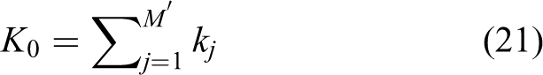
where M′ is the current element number in dynamic object storage area and the calculation formula of kj is

where grade j is the slave state possibility grade of the (x 0, y 0) and (xj , yj ).
d) Update static and dynamic storages
If K
0 is bigger than the minimum of
In this way, the information of the static objects and the dynamic objects can be updated, and the coordinate information of the two sets can be shown on the map.
Autonomous navigation method
According to the reconstructed map by FTGMM, the mobile robot can choose a collision-free path in the map. Especially, the static information consisting of static objects is used for global path planning, and the dynamic information is used for real-time obstacle avoidance. Based on the above, the whole navigation logic can be designed. The corresponding flow chart of the proposed navigation method is shown in Figure 5.

Navigation algorithm flowchart based on FTGNM. FTGNM: fuzzy 3-D navigation method.
As shown in Figure 5, the coordinates of signal sources and target point should be preset in the static storage in advance. The other unique obstacles such as wall can also be initialized in the static storage. Then, according to the static information, the real-time global path planning is conducted. During the mobile robot moves along with the planned path, the obstacles are detected by its sensors, and if the robot finds a dynamic obstacle in the front, it goes back with a distance and conducts obstacle avoidance keeping the global path broadly unchanged. Finally, the static and dynamic information are updated according to the fuzzy logic. The iteration is executed among above steps until the robot arrives at the target point.
Simulations and experiments
In this section, comparisons are conducted to demonstrate the efficiency of proposed method. First, tests are made for the WTPLM and the Two-PLM, through compared with the binocular ranging localization method (BRLM) 26,27 to illustrate the high accuracy of the WTPLM. In order to illustrate the practicability of the proposed fuzzy state division method in “Fuzzy judgment for two objects’ relationship” section, comparison is made between the linear binary divided method and the fuzzy division method. For showing the low amount of calculation the proposed FTGMM has, the practical mapping results of the proposed FTGMM, the traditional 2-D grid mapping method (Two-DGMM) 20 and the 3-D grid mapping method (Three-DGMM) 21 are compared. In the proposed FTGNM, the objects are divided into the static objects and dynamic objects, and the corresponding dynamic path planning method is designed. Hence, the final navigation results of the FTGNM and the vision-based navigation method 8,23 with all the objects being regarded as the static objects to demonstrate the efficiency of the proposed method.
As shown in Figure 6, the comparisons are tested in a structural lab whose width is about 10 m, length is 10 m, and height is 3 m. U-bot is used as the mobile robot platform, and the obtained information is then sent to a computer for running the navigation methods. All the conditions, such as the light, star point, target point, distributions of obstacles, and so on are the same in every methods.

Experimental environment.
Localization test
Multi-point localization
In SLA, if the signal sources are arranged reasonably, the number of the sensed signal sources should be always three or more than three; namely, the WTPLM is used most frequently so that it is most important in SLA. Hence, in order to demonstrate the efficiency of the proposed WTPLM, the WTPLM is compared with the single three-point localization method (STPLM) firstly. Considering the signal decay, different distances of the signal sources are tested. As shown in Figure 7, four signal sources marked A, B, C, and D are arranged and the localization results of WTPLM are compared with the results of the combination A, B, and C and results of the combination B, C, and D. During the test, the positions of the mobile robot are changed and the localization error is defined as


Multipoint localization comparison scene diagram.
where (x *, y *) is the real coordinate in the world projection frame and (xm , ym ) is the calculated coordinate by localization method.
Fifty positions are selected for testing, and the errors of WTPLM, STPLM with signal sources A, B, C (STPLM-ABC), and STPLM with signal sources B, C, D (STPLM-BCD) are compared and shown in Figure 8.

Multipoint localization comparison results.
From Figure 8, the localization errors of STPLM-ABC with the smallest distances waving from 0.0 m to 0.07 m, and the errors of STPLM-BCD with the largest distances waving from 0.0 m to 0.29 m. The reason is that the distribution of the signal sources can affect the localization accuracy of the STPLM. Meanwhile, the errors of WTPLM is 0.0–0.11 m which shows that the WTPLM could reduce the influence of the far signal sources so that the accuracy can be increased. In addition, for a generic application, WTPLM could weaken the influence of the abnormal points which could cause the STPLM failure.
Localization comparisons among different methods
Similarly, the WTPLM, the Two-PLM, and the BRLM 26,27 are compared. Especially, 100 positions are selected for testing, and the localization errors are shown in Figure 9, and the fluctuation results are shown in Table 1.
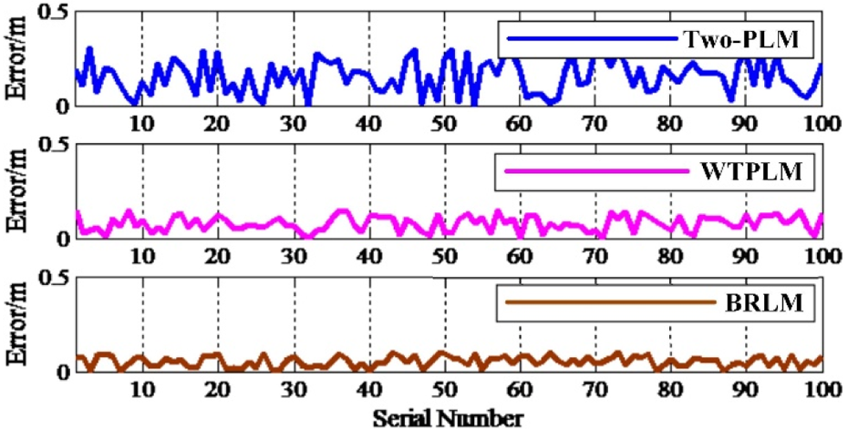
Localization comparison with different methods.
Fluctuation results comparison of different localization methods.
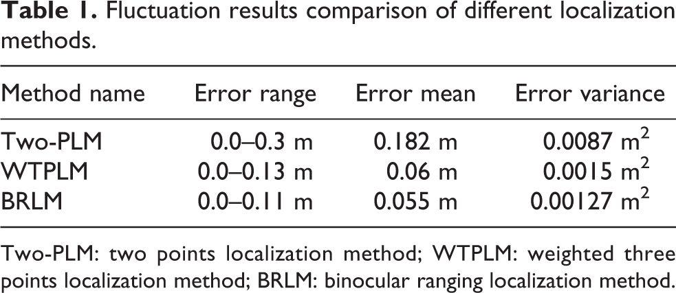
Two-PLM: two points localization method; WTPLM: weighted three points localization method; BRLM: binocular ranging localization method.
From Figure 9 and Table 1, it can be obtained that the accuracy of Two-PLM is lower than WTPLM and BRLM; meanwhile, the accuracy of WTPLM and BRLM is similar and is high enough for navigation. In this article, an SLA is proposed which designs different methods for different signal sources number. Among the proposed localization methods, the WTPLM, the Two-PLM, and the WALM, the accuracy of WTPLM is highest and the other methods could give a general guidance for the mobile robot. Consequently, the SLA gives a kind of synthetic localization architecture which could be a reference for other researches.
Fuzzy logic comparison
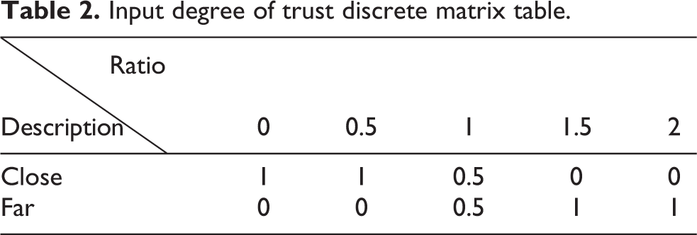
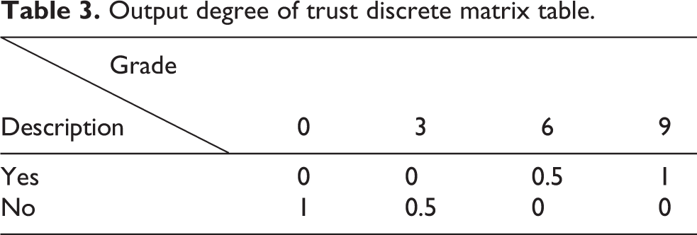
Setting the parameters of fuzzy logic with n = 5, m = 4, and ε = 0.8m, the corresponding fuzzy membership function matrix tables ψ and η are shown in Tables 2 and 3. Thirty-one test values are selected from 0 m to 2.4 m for every 0.08 m, and the values are fuzzed by equation (18). Then, the fuzzy output results through equations (19) and (20) can be calculated and the results are shown in Figures 10 and 11.
Input degree of trust discrete matrix table.
Output degree of trust discrete matrix table.
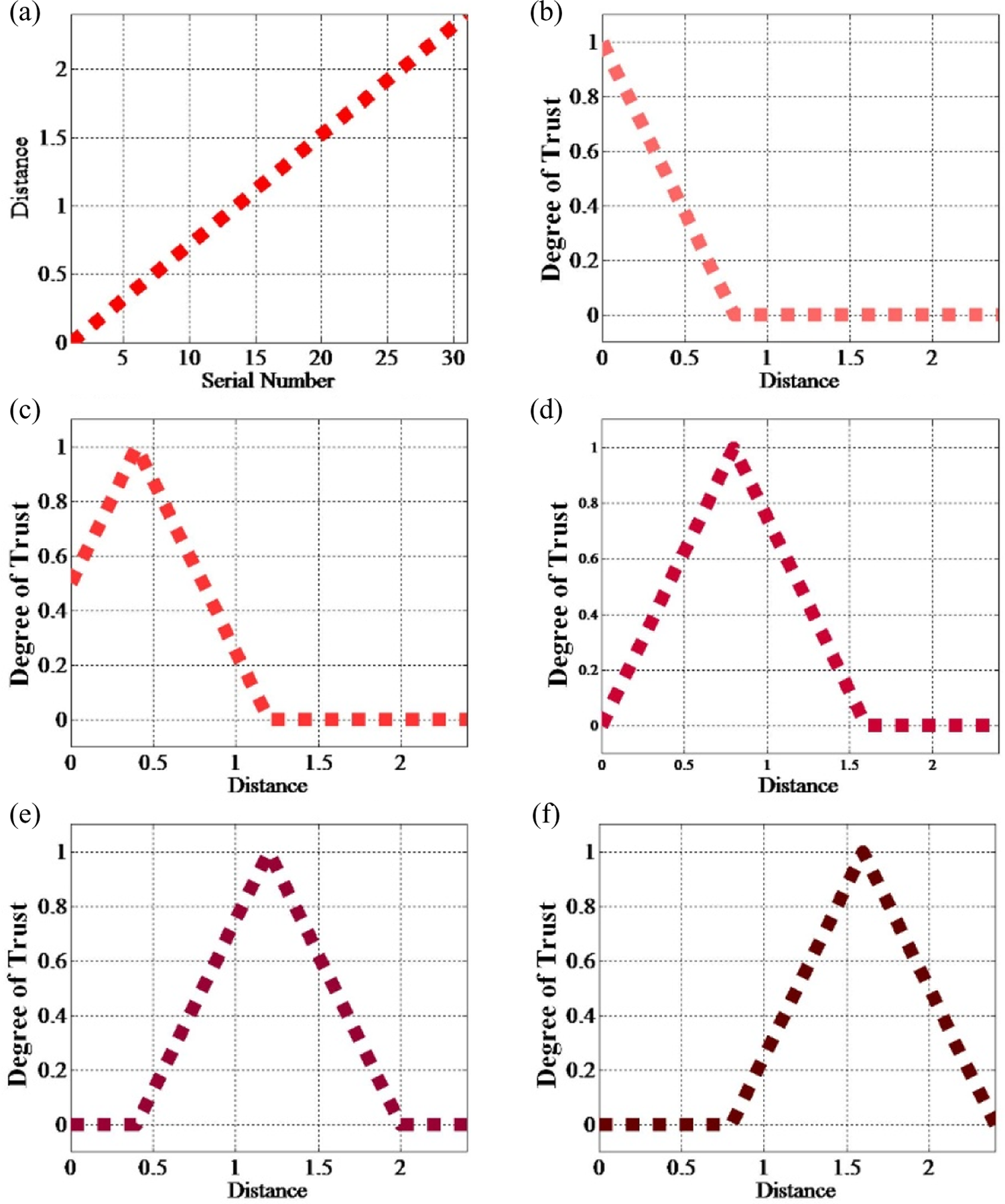
Fuzzy input diagram. (a) Linear distribution of input. (b) Fuzzy result of input relative to 0. (c) Fuzzy result of input relative to 0.5. (d) Fuzzy result of input relative to 1. (e) Fuzzy result of input relative to 1.5. (f) Fuzzy result of input relative to 2.

Fuzzy output diagram. (a) Fuzzy average result of output. (b) Fuzzy result distribution of grade 0. (c) Fuzzy result distribution of grade 3. (d) Fuzzy result distribution of grade 6. (e) Fuzzy result distribution of grade 9.
From Figures 10 and 11, linear input is converted into a smooth curve result, which is very suitable for real control system. Thus, this fuzzy division method is more applicable to the object state division than the absolute division with the linear binarization.
Mapping comparison
In order to prove that the method proposed in this article is of high efficiency and low amount of calculation, the FTGMM, Two-DGMM 20 , and Three-DGMM 21 are compared. During the comparison, the conditions such as the size of mesh are the same.
Saving information test
As shown in Figure 12, tables and boxes are ranged in the environment with sensed height value −50 and 80 cm; the “O” is the target point and the green curve is the robot’s moving trajectory.

Mapping comparison between FTGMM and Two-DGMM. (a) Photo sequence of passing the table by FTGMM. (b) Photo sequence of going around the table by Two-DGMM. (c) Moving trajectory in FTGNA (fuzzy three-dimensional grid navigation algorithm). (d) Moving trajectory in Two-DGMM. FTGMM: fuzzy 3-D grid mapping method; Two-DGMM: 2-D grid mapping method.
It can be observed from Figure 12(a) and (b) that the mobile robot can pass through the table by FTGNM, while it goes around the table by Two-DGMM. The reason is that in 2-D grid, the table is not passable, which means 2-D grid lacks of the 3-D environmental information. Therefore, FTGNM could save more 3-D environmental information than 2-D grid while ensure the low calculation amount.
Amount of calculation test
Similar to 2-D grid map, in Three-DGMM, the environment is divided into many cubes, and the distribution information of the objects are stored in the cubes. The reconstruction for the experimental scene shown in Figure 6 is conducted by proposed FTGMM and Three-DGMM, respectively, and the reconstructed results are shown in Figure 13.

Reconstructed map comparison between FTGMM and Three-DGMM. (a) Identifier map of FTGMM. (b) Height map of FTGMM. (c) Reconstructed map of Three-DGMM. FTGMM: fuzzy 3-D grid mapping method; Three-DGMM: 3-D grid mapping method.
It can be seen in Figure 13 that the proposed FTGMM uses dual 2-D grid map to describe the scene, as shown in Figure 13(a) and (b). The Three-DGMM uses a 3-D grid to describe the scene, as shown in Figure 13(c), while there are many 3-D meshes having no elements and that will be waste of the resources. In addition, it is obvious that when conducting the path planning, the amount of calculation of searching best collision-free path in Three-DGMM is larger than the proposed FTGMM. Therefore, it is proved that FTGMM can reduce the amount of calculation while ensuring enough 3-D environmental information which could satisfy the hard real-time property of the embed robot system better.
Navigation test
This article proposes an FTGNM where the state of objects is divided into static and dynamic objects, and the global path planning is performed with the static information, and the real-time obstacle avoidance is executed with the dynamic information. In order to illustrate the efficiency of the proposed FTGNM, it is compared with the vision-based navigation method, 8,23 where the objects are regarded as the same and the path is planned with all the sensed objects.
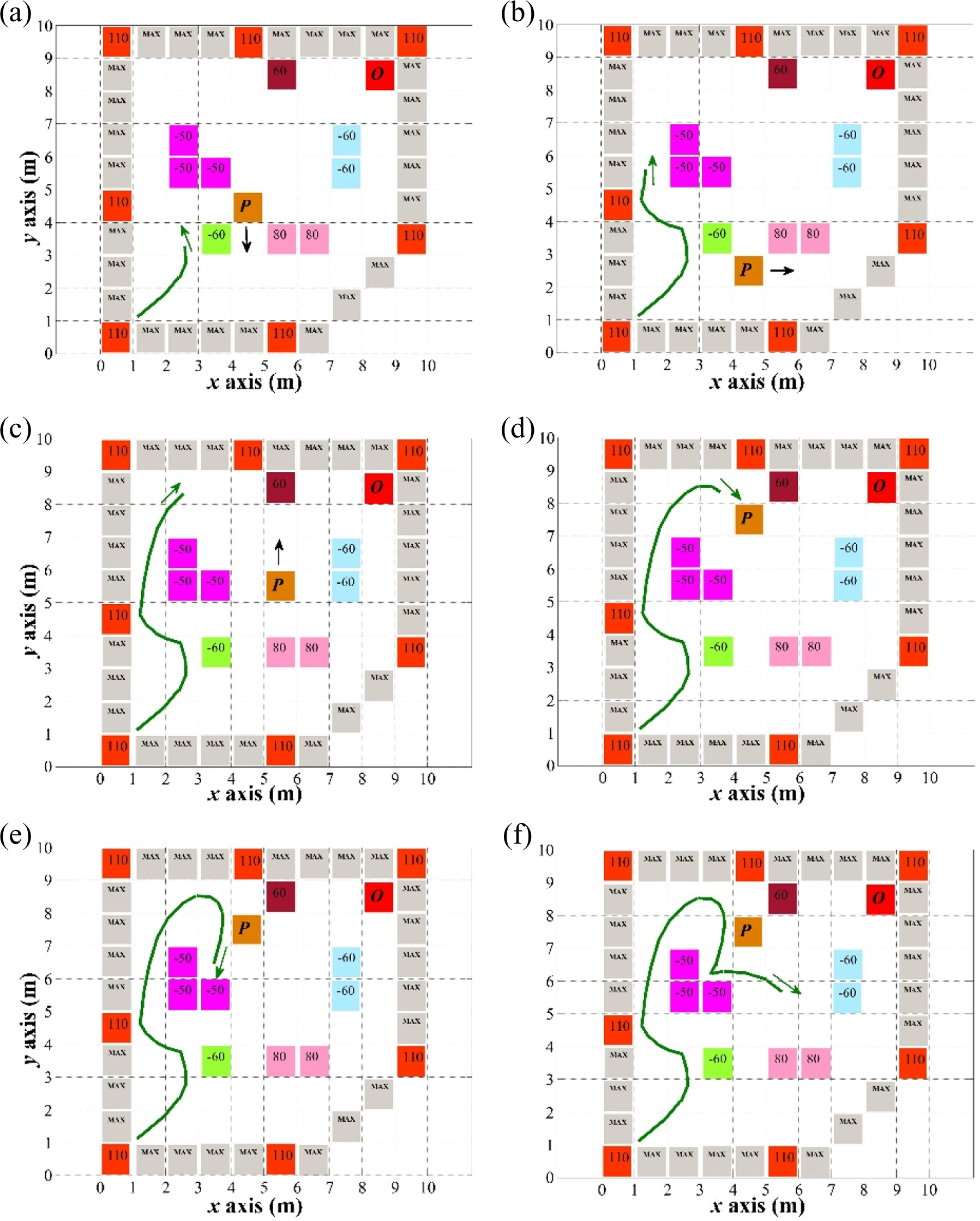
As shown in Figure 6, a person is walking in the scene as the moving obstacles. The FTGNM conducts navigation with its sensors. The vision-based navigation method performs navigation with a Kinect. Kinect is a line of motion sensing input devices by Microsoft for Xbox 360 and Xbox One video game consoles and Microsoft Windows PCs. Through the Kinect and RGB recognition method, an object can be recognized and the distance between the object and the robot can be obtained. With the distance information, the vision-based navigation method can calculate its coordinate and obtain the environmental map. At last, the navigation could be executed. The conditions of two methods are the same for a fair comparison. The map reconstructions of two methods are all conducted during robot’s moving and the map is updated continuously. Every methods are test for 10 times and the average motion trajectories are shown in Figures 14 and 15. The real-time trajectories in every T=30 s time are recorded. In Figures 14 and 15, the red dashed is the global planed path of the FTGNM based on the static map information, and the green curve is the actual path.

Navigation result of FTGNM. (a) 1T. (b) 2T. (c) 3T. (d) 4T. (e) 5T. (f) 6T. FTGNM: fuzzy 3-D navigation method.
Navigation result of vision-based navigation method. (a) 1T. (b) 2T. (c) 3T. (d) 4T. (e) 5T. (f) 6T. (g) 7T. (h) 8T.
From Figure 14, it is obvious that the global planed path is a guidance for the mobile robot and the real-time obstacle avoidance is conducted, which leads to that the general directions of the global path and the actual path are the same in FTGNM. Meanwhile, compared to the FTGNM, the path of the vision-based navigation is smoother. However, the objects in this method are all regarded as the obstacle, and there is no global path for guidance. For instance, in Figure 15(d), the robot regards the person as a static object, and the global path is replanned, while in FTGNM, the person is regarded as dynamic object and for real-time obstacle avoidance. So, the time cost of vision-based navigation method is longer than FTGNM, 6 T, with 8 T. It can be proved that the faster and higher efficient navigation can be achieved through dividing the state of objects into static and dynamic objects fuzzily with the static information for global path planning and the dynamic information for real-time obstacle avoidance.
In addition, FTGNM needs signal sources to be set in advance, while the vision-based navigation methods don’t need that. However, along with the development of technology, many public equipment, such as the Wi-Fi base stations, mobile phone signal base stations, and so on, can be used as the signal sources. Hence, if the environment has the condition of signal sources, the proposed FTGNM may conduct the more efficient navigation than the vision-based navigation, no matter indoor or outdoor.
Conclusions
Since problems such as complex modeling, large amount of calculation, lacking of environmental information, and so on always exist in autonomous navigation methods, this article proposes an FTGNM to achieve fast and practical self-navigation. To be specific, an SLA is designed for accuracy localization with different signal sources number. Then, an FTGMM is presented with dual 2-D grid maps describing a 3-D map to reduce the amount of calculation of mapping and path planning. Especially, according to the fuzzy logic, the state of objects is divided into static and dynamic objects, and the two objects are used for global path planning and real-time obstacle avoidance, respectively, to promote the navigation efficiency. The results of simulations and experiments demonstrate that the proposed FTGNM can achieve fast and efficient navigation while ensure the low amount of calculation that has a certain promoting for the mobile robot autonomous navigation technology field.
Footnotes
Declaration of conflicting interests
The author(s) declared no potential conflicts of interest with respect to the research, authorship, and/or publication of this article.
Funding
The author(s) disclosed receipt of the following financial support for the research, authorship, and/or publication of this article: The research work was supported by the National Natural Science Foundation of China (61373120), the National Natural Science Foundation of Shaanxi (2015JM6308), the fund of national ministries (9140A15090115HK03216), the Open Project Foundation of Information Technology Research Base of Civil Aviation Administration of China (CAACITRB-201402), and the Fundamental Research Funds for the Central Universities (3102015JSJ0005 and 3102014JSJ0015).