
Abstract
In this article, we discuss the temperature regulation problem of robotic thermal tactile system under unknown time-varying disturbances. In order to improve the disturbance rejection property of the thermal system, a composite controller is presented. First, a generalized proportional integral observer is introduced to estimate the system disturbances, which generally include model uncertainties and external disturbances. Second, a feedback control is designed using feedback linearization control technique. A composite temperature controller is obtained as a composition of feedback linearization–based controller plus feed-forward compensation based on generalized proportional integral observer. A rigorous analysis shows that the proposed scheme can enhance the disturbance rejection property of the thermal system. Simulation and experimental comparisons with two other control methods, that is, the composite control method with feedback linearization–based control plus feed-forward compensation based on disturbance observer and the proportional integral control method, are given to verify that the proposed method exhibits a much better disturbance rejection performance.
Keywords
Introduction
In recent years, the Peltier devices are widely used in many applications, from thermal stabilization to micro-refrigeration. Generally, the Peltier devices are most often used in applications where an object needs to be maintained at a constant temperature or needs to be cooled below the surrounding temperature. As a heat pump, 1 Peltier device can generate a heat transfer from one side to the other side by a direct current (DC) power source. 2 Because the Peltier devices have a relatively fast response among the thermal devices, they have been used as thermal perceptron for the telepresence systems, 3 –6,7 the reproduction of finger’s temperature transition, 8,9 and the thermal bilateral control system. 4 In this case, we need to control the Peltier device precisely in order to obtain fast and exact responses both in temperature and in heat flux.
It is difficult to obtain accurate enough models that relate the input current to the temperature of Peltier device. This is because of the nonlinear behavior of the Peltier device that acts as a floating load for the voltage supply and Peltier effect that occurs within it. 2 In the study by Lineykin and Ben-Yaakov, 10 the thermal model of a Peltier device based on thermal network method has been devised. Equivalent circuit is a convenient tool for electronic engineers. This helps to show the problem in “electronic circuit language” and contributes to solving the cooling or heating problems without the need for expertise in thermal engineering.
In order to simulate a thermal tactile perceptron, temperature control is important. However, when a Peltier device works, Joule heat occurs with respect to the electric resistance. Since Peltier device’s parameters, such as Seebeck coefficient, depend on temperature, variations may occur between the nominal and actual values of coefficient. Furthermore, when an object or a person’s hand touches the surface of Peltier device, heat flow disturbances are introduced from outside. All above factors perturb the system’s heat exchange. So the control of the thermal system is not an easy task owning to their nonlinearities and uncertainties.
Conventional proportional integral (PI) control, which is often used to regulate the performance of the control system, is a linear control scheme. With the advantages of simple implementation, PI control scheme has been used in thermal system. 11,12 However, the overall performance could not be ensured owing to the existing of nonlinearities and disturbances. So far, numerous nonlinear control methods have been reported to enhance the control performance of thermal system, such as internal model control, 13 operator-based nonlinear control method, 14 and sliding mode control. 15 These approaches improve the control performance of thermal system in different aspects.
However, the disturbances, including parameter variations and external heat disturbances, will cause a degradation in the system performance if the controller does not have enough ability to reject them. Conventional control methods based on feedback design usually cannot react directly and quickly enough to reject these disturbances, although these control methods can finally suppress them through feedback regulation in a relatively slow way. One effective way of improving system performance in such cases is to introduce a feed-forward disturbances compensation part into the controller in addition to the conventional feedback part.
So the disturbance rejection technique 16 –22 is required in the controller design. Compared with other robust control schemes, disturbance rejection technique has two distinct features. One feature is that disturbance observer (DOB)–based compensation can be considered as a “patch” for existing controllers which may have unsatisfactory disturbance attenuation and robustness against uncertainties. The benefit of disturbance compensation is that there is no change to the baseline controller which may have been wildly used and developed for many years. The second feature is that disturbance rejection technique is not a worst-case-based design.
When an object or a person’s hand touches the surface of Peltier, there exists a temperature difference which generates heat transfer between two contact surfaces. The heat disturbances are determined indirectly by the temperature difference. These external disturbances are sometimes fast time varying if the surface’s contact force or contact area changes. To estimate the heat disturbances, DOB has been employed for thermal system in the studies by Morimitsu and Katsura. 12,23 However, in the presence of fast time-varying heat disturbances, the disturbances of thermal system cannot be rejected by PI and feedback linearization (FL) + DOB effectively. The reason is that PI control is a feedback control method which attenuates disturbances based on the tracking error in a relatively slow way. PI does not explicitly take into account disturbance or uncertainty during the design of controller. On the other hand, DOB can only estimate accurately the slow time-varying disturbances, 16 so FL + DOB does not work well in the presence of fast time-varying disturbances. Considering that these fast time-varying disturbances can be approximately expressed by a Taylor polynomial, a generalized proportional integral (GPI) observer 24 method is proposed. The GPI observer, which belongs to another kind of disturbance estimation techniques, can estimate polynomial form disturbances effectively. Then the estimate value of disturbances can be employed in the feed-forward compensation design to improve the performance of the system.
For the thermal control problem, in this article, we propose a composite control law to improve the disturbance rejection capability of the thermal system. A GPI observer in the feedback path provides an estimate of the disturbances including parameter variations, Joule heat, and fast time-varying external heat disturbances. Then the estimated value of disturbances is employed in the feed-forward design of the control law such that the performance degradation caused by the disturbances can be suppressed. Then, since the thermal system has some very strong nonlinear terms, such as current square and coupling of current and state, we design a feedback control law using FL)control technique, 25 which can generate a nominal linear model and result in global stability. Our control method can be considered as FL-based control plus feed-forward compensation based on GPI (FL + GPI). We show that the state can be asymptotically stabilized to the set point and the closed-loop system with composite control law (FL + GPI) shows a better disturbance rejection property. Comparative studies with two other methods, including a composite control method of FL-based control plus feed-forward compensation based on DOB (FL+DOB) and a PI control method, are also carried out by simulations and experiments.
This article is organized as follows. In “Modeling of thermal system” section, we present the heat model of the thermal system. Design and stability analysis of proposed GPI observer method and the composite controller based on GPI observer are presented in “Controller design” section. Simulations and experimental results of the thermal system are presented in “Simulation and experiment” section. Finally, conclusions are drawn in the last section.
Modeling of thermal system
The Peltier thermal system is depicted in Figure 1. It is composed of an object, a sensor, a Peltier device, and a Heat sink. To, Tc, and Th are the temperatures of outside object, cold side, and hot side of the device, respectively. The heat sink is applied to maintain Th to be constant. Just using a DC power source, we can control the Peltier device to receive a desired temperature.

Schematic representation of the thermal system.
A thermal network method based on an equivalent circuit has been proposed for the thermal modeling in the study by Drif et al. 4 and applied successfully to extract the parameters of the thermal model from the manufactures’ data. In the studies by Morimitsu and Katsura, 12,23 this thermal model has been used. We also used this thermal model. When current flows to the thermal system, heat transmission occurs in the device. Using thermal network method, we can obtain the equivalent circuit shown in Figure 2.

Equivalent circuit of the thermal system.
In Figure 2, qin represents the value of heat per unit time flowing into the device from the object when the object touches the surface of Peltier, Ro denotes the contact thermal resistance between the object and the device, Rp is the thermal resistance in the device, and Co and Cc are, respectively, the amount of heat in the object contact surface and the amount of heat between the sensor and the surface of the device. Then, the temperature model of the hot side is written as
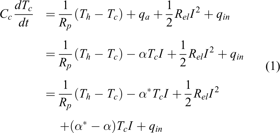
where qa = −αTcI is the amount of heat per unit time absorbed in the Peltier device, α is the Seebeck coefficient, I is the current, and α* denotes the reference Seebeck coefficient.
Controller design
A high-performance thermal system must provide a good dynamic temperature tracking performance as well as being insensitive to the parameter variations and external heat disturbances. Note that a GPI observer can observe the disturbances of the system, and the closed-loop system with composite control can ensure an asymptotic convergence of the temperature to the set point. Therefore, to achieve a better control performance and disturbance rejection property, a composite controller (FL + GPI) is designed for the temperature control of thermal system. The design procedure of the current controller is presented as follows.
Design of a GPI observer
In practice, disturbance rejection is an important criterion to evaluate the performance of control system. Disturbances in the system will degrade the performance of control system if we do not consider a corresponding feed-forward control design to compensate them. Thermal system is generally affected by the disturbances including parameter variations and external fast time-varying disturbances. The disturbances can be approximately expressed by a Taylor polynomial. In order to achieve a good performance in both temperature command tracking and the heat disturbance regulation, we introduce a GPI observer for the thermal control system. The detail of the principle of GPI observer can be found in the study by Kim et al. 24
According to the normalized form proposed by designing GPI observer, we can rewrite temperature dynamic equation (1) as

where d = (α* − α)TcI + qin can be considered as the lumped disturbances, including Joule heat, variations of coefficient, and the external disturbances.
Denote x = Tc, u = I. From equation (2), a thermal model of the device can be described as

where
Assumption 1
Suppose that the lumped disturbances d is a completely unknown bounded perturbation, and d can be modeled by a Taylor polynomial of a fixed n degree
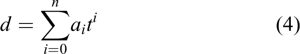
where each ai is a constant coefficient but unknown.
According to assumption 1, we can design a GPI observer 24 for system (3) as follows

with

where Li, i = 0, ⋯, n are the observer gains to be designed. Figure 3 shows an architecture of the generalized DOB.

Block diagram of the GPI observer for the thermal system. GPI: generalized proportional integral.
Theorem 1
Consider the system (3) under the lumped disturbances which satisfy assumption 1. The estimate of the DOB of equation (5) can asymptotically track the lumped disturbances if the observer gains Li, i = 0, ⋯, n are chosen such that the polynomial
Proof
By denoting
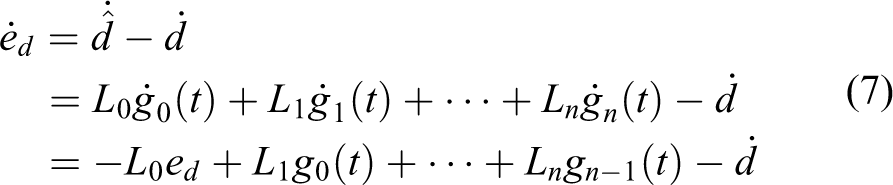
Keeping calculating the derivatives of observer error dynamics (7) until the appearance of d(n+1), we have

Considering the case that the disturbances satisfy assumption 1, that is, d(n+1) = 0, it is obtained from equation (8) that the error dynamics of observer is governed by

where Li, i = 0,⋯, n that satisfy the polynomial
The design of composite control
Because the x is available for feedback and the h can be known, we get the controller using the FL technique
to reduce the model to

Using the feedback control law and feed-forward compensation, the auxiliary control v is designed as

where xref denotes the reference temperature, k > 0.
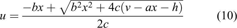
So we can obtain the input u

Stability analysis of the closed-loop system
Lemma 1
The following single-input linear system 26

is asymptotically stable if A is Hurwitz matrix and u is bounded and satisfies
Theorem 2
Considering system (3) under the designed control law (13), the temperature of Peltier surface will asymptotically converge to the desired reference temperature, that is, the tracking error of system is asymptotically stable if k > 0.
Proof
We define the temperature error between the feedback temperature x of the closed-loop system and the reference temperature xref as

For system (3), if the input u is chosen as equation (13), we can obtain the tracking error system

where k > 0. Using the result of theorem 1, it can be found that
Simulation and experiment
To demonstrate the efficiency of the proposed composite control method, simulations and experiments on a thermal system have been done. Three control methods, that is, FL + GPI control, FL + DOB control, and PI control, are applied to the thermal system. Before simulation and experiment, the thermal contact resistance can be given from the study by Ho and Jones. 27 We take a modest value Ro = 3.1739 w/K. As the Peltier module can be regarded as a single plate, the thermal resistance of conduction in the Peltier module is gotten from its thickness divided by its thermal conductivity. So the parameter Rp = 0.8929 w/K. The electric resistance of Peltier module can be directly measured by a multimeter, Rel = 1.70 Ω. The nominal values of the thermal capacitance and Seebeck coefficient are used. 12 And a, b, c, and h can be calculated from above parameters. The system parameters and other experimental parameters are listed in Table 1. 2,12 To have a fair comparison, first the control inputs of three algorithms have the same saturation limit and, second, these three methods all achieve relatively good performances by regulating the parameters of each control algorithm.
Model parameters of the thermal system.

Simulation
In order to show that the proposed FL + GPI control method has a better disturbances rejection ability against not only the slow-varying disturbances but also the fast time-varying disturbances, the cubic polynomial disturbances and the sawtooth-shaped disturbances are considered to show the effectiveness of the proposed FL + GPI method in this section. In order to guarantee these, three methods all achieve relatively good performances. The parameters of three control algorithms are chosen as follows. To guarantee the convergence of equation (9) when n = 3, the observer gain vectors are chosen as L0 = 80, L1 = 2400, L2 = 2,000, L3 = 160,000, respectively, such that the poles related to equation (9) are pi = −40, i = 1,⋯, 4. The DOB gain is chosen as L = 38. The PI gains are given as the proportional gain kp = 5 and the integral gain ki = 5. The FL + DOB feedback control gain is chosen as optimized: k = 9. The feedback control gain in FL + GPI method is designed as k = 10. The initial state of system (2) is x0 = 300 K (27°C). The control objective is to remove the disturbances. Here, the set point of temperature is 293 K (20°C). Saturation limit is u = ±4 A. The results of the simulation are shown in Figure 4 to 9.

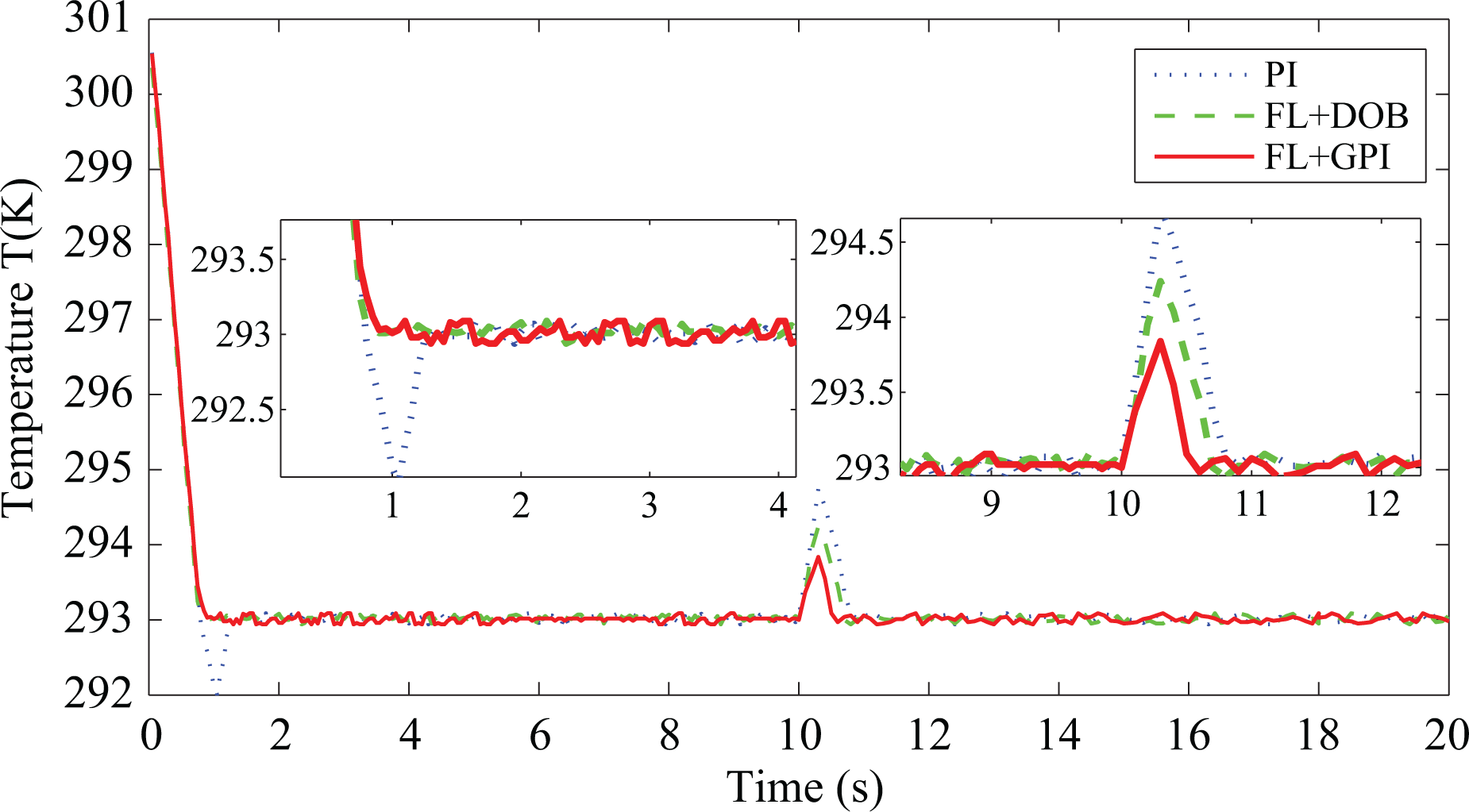
The temperature’s response curves of the thermal control system in the case of 293 K reference temperature (simulation case 1).

The controllers’ output current curves of the thermal control system in the case of 293 K reference temperature (simulation case 1).
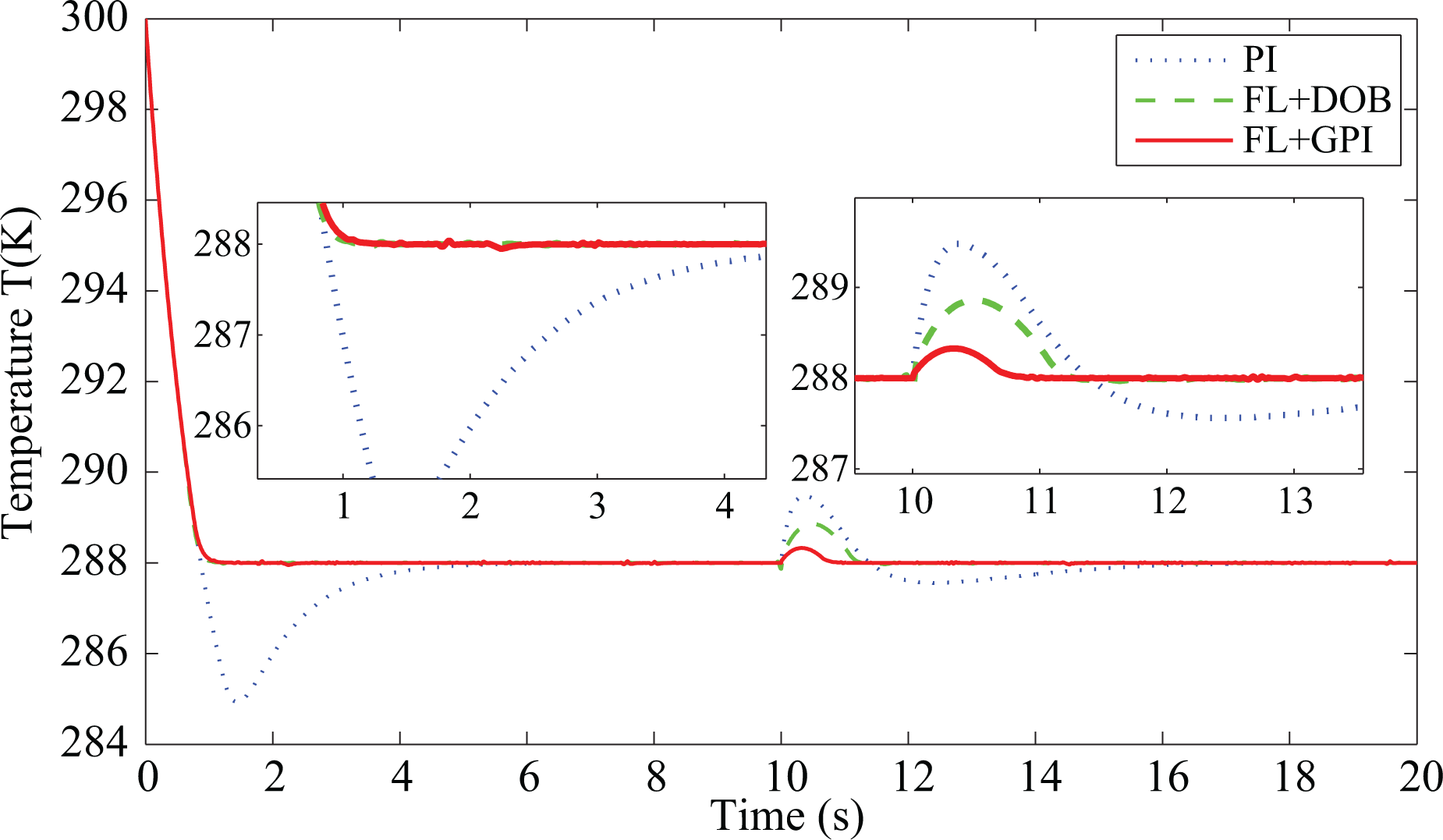
The temperature’s response curves of the thermal control system in the case of 288 K reference temperature (simulation case 1).
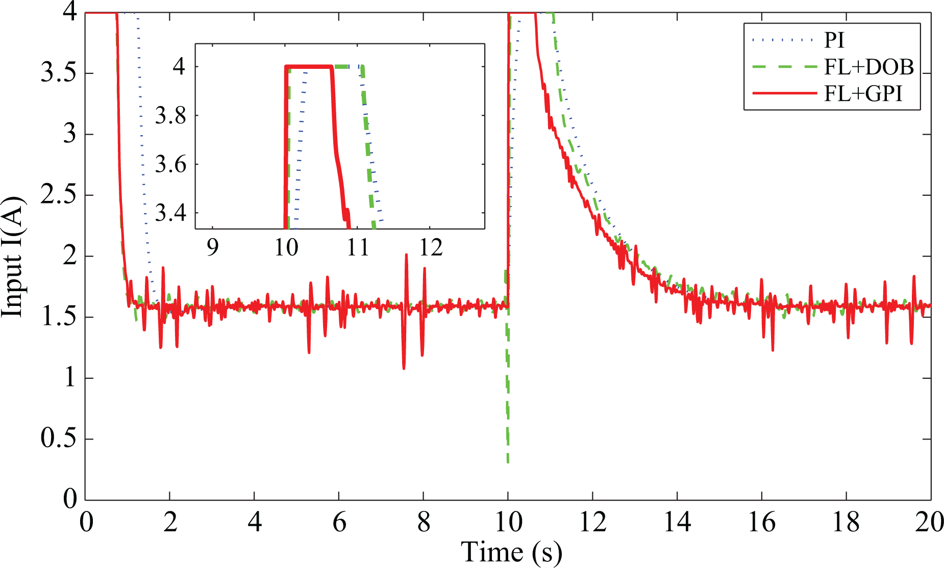
The controllers’ output current curves of the thermal control system in the case of 288 K reference temperature (simulation case 1).

The temperature’s response curves of the thermal control system in the case of 293 K reference temperature (simulation case 2).

The controllers’ output current curves of the thermal control system in the case of 293 K reference temperature (simulation case 2).
In simulation case 1, the cubic polynomial disturbances are considered. The temperature response curves based on FL + GPI, FL + DOB, and PI controller are shown in Figure 4. When a disturbance d = −0.05778t3 + 2.752t2 − 43.77t + 232.5 is applied at t = 10 s, it vanishes at t = 16 s. It can be seen from Table 2 that the FL + GPI control method gives a shorter setting time compared with PI control and FL + DOB control. On the other hand, it can be seen from Figure 4 and Table 2 that the temperature response under our method recovers to 293 Kin about 10.5 s, compared with 14.1 s of PI control and 11.4 s of FL + DOB control. Meanwhile, the corresponding control inputs of three algorithms shown in Figure 5 have the same saturation limit. It can be shown that our method recovers faster against the polynomial disturbances. As shown in Figures 4 and 5, the proposed FL + GPI method has achieved a promising performance in rejecting such polynomial disturbances.
Comparison of the simulation performance indexes.

OS: overshoot, PI: proportional integral; FL: feedback linearization; DOB: disturbance observer; GPI: generalized proportional integral.
In simulation case 2, in order to show that the proposed FL + GPI control method has a better disturbance rejection property in cases where the disturbances are fast time varying, sawtooth-shaped disturbances are considered. The period of the sawtooth-shaped wave is 1 s, and the peak is 14. When the sawtooth-shaped disturbance is applied at t = 10 s, it vanishes at t = 15 s. The response curves of the temperature under FL + GPI, FL + DOB, and PI are shown in Figure 8. It can be seen from Table 2 that the FL + GPI control method gives a shorter setting time compared with PI control and FL + DOB control. As shown in Table 2, it can be found that the maximum increasing temperature with proposed FL + GPI method caused by sawtooth-shaped disturbance is only 0.012 K, while the corresponding control inputs of three algorithms have the same saturation limit. It can be concluded that our method has a better fast time-varying disturbances rejection property.
As shown in Figures 4 to 9, the proposed FL + GPI control method has shown a better disturbances rejection ability against not only the slow-varying disturbances but also the fast time-varying disturbances.
Considering the robustness of the thermal control system lastly, the comparison simulation results are also shown in Figures 6 and 7 and 10 and 11 when both case 1 and case 2 reference temperature signals are given as 288 K (15°C). The parameters of three controllers at different operation conditions are still the same as that of the 293 K case.

The temperature’s response curves of the thermal control system in the case of 288 K reference temperature (simulation case 2).
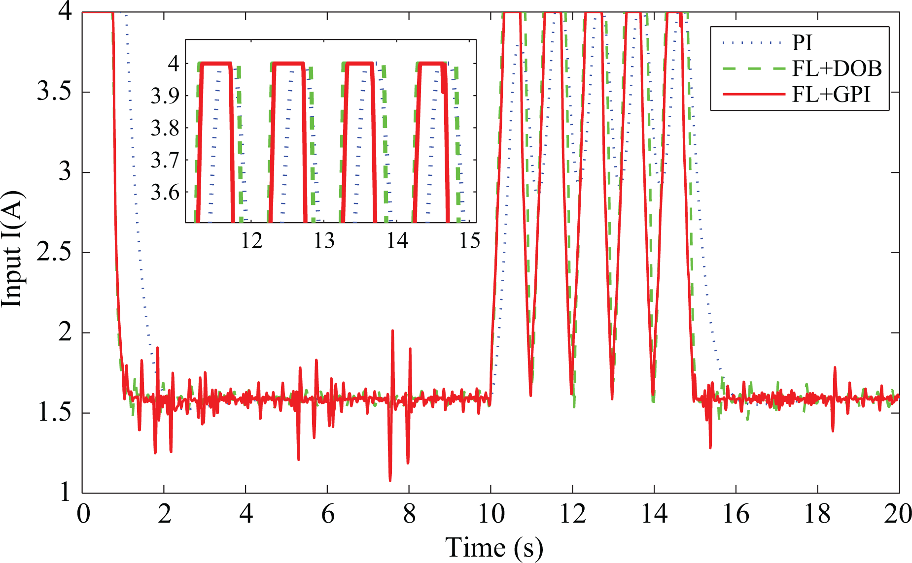
The controllers’ output current curves of the thermal control system in the case of 288 K reference temperature (simulation case 2).
A comparison of performance indexes on the two cases at different conditions is shown in Table 2. It can be observed that in both these two different work conditions, the proposed FL + GPI observer method has achieved a promising performance in rejecting such polynomial disturbances and sawtooth-shaped disturbances while maintaining a good dynamic performance.
Experiment
In order to verify the validity of the proposed FL + GPI method, we have conducted experiments of temperature control. The experimental setup is based on OMAPL138 (Tronlong, Guangzhou, China) processor that can implement data collection and computation. The rated current and nominal voltage are 4 A and 5 V, respectively. The whole temperature control algorithms including the two-phase enhanced high resolution pulse width modulation (eHRPWM) are implemented by the program of the OMAPL138 with a clock frequency of 456 MHz. The control algorithms implemented using C++ program. Three-wire measurement by applying PT100 is adopted to ensure the measurement precision of the temperature. The sampling period for control is 1 ms. The TA7257p (TOSHIBA, Japan) module is driven by eHRPWM inverter with an intelligent power module with a switching frequency of 1 MHz. The current is controlled by the change of phase voltage with the change of duty ratio of PWM. The saturation limit of the reference current is ±4 A. The configuration experimental test setup and its photo are illustrated in Figures 12 and 13. It consists of a Peltier pad, a thermal sensor for contact temperature, a controller, a signal conditioning module, and a heat sink.

Configuration of experimental test setup.

Experimental test setup.
The value of the desired temperature is set as 293 K (20°C). Parameters are chosen as FL + GPI, k = 6, L0 = 80, L1 = 2400, L2 = 32,000, and L3 = 160,000; FL + DOB, k = 9, and L = 38; and PI, kp = 5, and ki = 2. When the temperature of the Peltier surface is kept at 293 K, a finger touches the Peltier surface suddenly at t = 10 s and removes suddenly after some duration.
The experimental results of FL + GPI, FL + DOB, and PI methods are given in Figure 14. Figure 14 shows that the Peltier temperature quickly converges to the reference shortly after startup when the reference temperature is given as 293 K. Compared with other two controllers, the FL + GPI method shows a smallest overshoot (OS) and a shortest settling time. The corresponding controller output current is shown in Figure 15. From Figures 14 and 15, it is obviously shown that the proposed scheme can effectively attenuate the temperature deviation caused by the disturbance variations while maintaining a good dynamic performance.
The temperature’s response curves of the thermal control system in the case of 293 K reference temperature (experiment).

The controllers’ output current curves of the thermal control system in the case of 293 K reference temperature (experiment).
Considering the robustness of the thermal control system lastly, the comparison experiment results are also shown in Figures 16 to 19 when the reference temperature signals are given as 288 K (15°C) and 283 K (10°C), respectively. The parameters of three controllers at different operation conditions are still the same as that of the 293 K case.

The temperature’s response curves of the thermal control system in the case of 288 K reference temperature (experiment).

The controllers’ output current curves of the thermal control system in the case of 288 K reference temperature (experiment).

The temperature’s response curves of the thermal control system in the case of 283 K reference temperature (experiment).

The controllers’ output current curves of the thermal control system in the case of 283 K reference temperature (experiment).
There are also some performance indexes introduced in this work, such as OS (%), settling time (ts), and maximum increase of temperature caused by fingers contact. The tolerance band of settling time in this article is selected as 2%. A comparison of performance indexes on the three methods at different conditions is shown in Table 3. Because the thermal resistance is related to these factors, such as pressure and contact area, there are slight differences between simulation and experiment. It can be observed that in all these three different work conditions, the proposed method has the smallest temperature increase on the whole when a disturbance is applied.
Comparison of the experiment performance indexes.
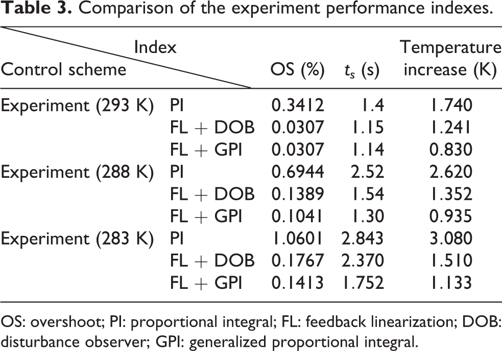
OS: overshoot; PI: proportional integral; FL: feedback linearization; DOB: disturbance observer; GPI: generalized proportional integral.
Experimental result at different conditions indicates that the proposed FL + GPI control method has a better disturbance rejection property while maintaining a good dynamic performance.
Conclusion
In this article, the design and implementation of a composite temperature controller using FL-based control technique and a GPI observer for thermal system has been investigated. First, a GPI observer has been introduced to estimate the system disturbances and the estimated value has been used in feed-forward compensation design. Second, for the feedback regulation part, an FL-based control has been designed. A rigorous stability analysis has been provided for the closed-loop thermal system. Finally, the effectiveness of the proposed method has been demonstrated by simulation and experimental results. The simulation and experimental results show that the closed-loop system under the proposed method has achieved a satisfying dynamic performance. Through disturbance estimation for feed-forward compensation, the compensator generates a corrective input signal to reject disturbances so that the controller shows a better disturbance rejection property by comparison with two other methods of FL + DOB and PI.
Footnotes
Declaration of conflicting interests
The author(s) declared no potential conflicts of interest with respect to the research, authorship, and/or publication of this article.
Funding
The author(s) disclosed receipt of the following financial support for the research, authorship, and/or publication of this article: This work was supported by the National Natural Science Foundation of China (U1531104) and 333 Talent Plan Project of Jiangsu Province.