
Abstract
This article mainly studies the trajectory tracking control for quadrotor unmanned aerial vehicle with unknown time-varying disturbances including parametric uncertainties, model errors, and external disturbances such as wind effects. Conventional backstepping control schemes usually cannot guarantee the performance when it faces the time-varying disturbances. Improved schemes, such as integral backstepping, can only compensate the disturbances in a relatively slow way. By introducing disturbance observer technology into the design of controller, a composite generalized proportional integral observer–based robust control design method is developed. First, by utilizing the generalized proportional integral observer, the lumped time-varying disturbances of unmanned aerial vehicle are estimated. Secondly, combining the value of disturbance estimation and feedforward controller by using backstepping control technology together, a composite controller has been developed, which can be called as backstepping control + generalized proportional integral observer. The proposed control method has a better capability of disturbance rejection and is easy to implement. Simulation and experimental results illustrate the good robustness and tracking performance of the proposed scheme.
Keywords
Introduction
In recent years, there are growing concerns about quadrotor drone with the expanding scope of application. 1 Compared with traditional fixed wing aircrafts, the quadrotor unmanned aerial vehicle (UAV) has distinct advantages, that is, simple mechanical structure, agile maneuverability and capability of vertical takeoff and landing, and so on. The quadrotors have good mobilities, which are useful for rescue work where people in danger environment, especially in cluttered or complicated space. These distinguishing advantages allow the quadrotor UAV to be broadly used in military fields and civil industries, such as filmmaking, traffic monitoring, environmental surveillance, and searching and rescue operations. 2
In these complex tasks, the performance of quadrotor UAV largely lies in the design of flight controller. With the expanding application, great effort of researchers is devoted to the controller design of quadrotor UAV. Various control methods have been reported in the literature. 3 The proportional integral derivative (PID) control has been very widely used in quadrotor control, 4 mainly because the designed controller is simple and easy to implement. However, due to the linear characteristics, which limited the control precision, PID cannot guarantee the increasing demand for tracking accuracy. With the development of microelectronic technology, it allowed various advanced nonlinear control algorithms being used in quadrotor control, such as sliding mode controller, 5 backstepping controller, 6 and model predictive controller. 7 Later, for the purpose of enhancing the robustness of quadrotor UAV system, many advanced control theories were proposed for the quadrotor UAV design, such as methods based on hierarchy theory 8 and Lyapunov function. 9 The effectiveness of the methods mentioned above is proven theoretically and experimentally.
In addition, model mismatches and external disturbances, like rotor damages, payloads, and winds, are not considered in the controller design of the proposed schemes mentioned above, which obviously degraded the performance of the flight controllers. 10 Considering the effect of model errors, external disturbances, and parametric uncertainties, feedforward compensation design of those disturbances can be proved an efficient method. Nevertheless, it is unrealistic to measure all these disturbances because of the complexity and cost. Under these circumstances, the disturbance observer technique can be regarded as an alternative. Some disturbance observer–based control schemes have been used in the quadrotor UAV in recent years. 11 An extended state observer (ESO) is developed to estimate the lumped disturbance, which includes the uncertainties and external disturbances of quadrotor UAV control. 12 The effects of the disturbance can be estimated and compensated by feedforward in real time, and the results demonstrated a better immunity to disturbance. Considering the problems of parameter variations and noise in quadrotor UAV system, a sliding model observer has been proposed by Madani and Benallegue. 13 However, the abovementioned disturbance observer methods mainly focus on slow-varying disturbances. In real applications, the disturbances in UAV may be caused by winds, friction, and model errors, which are very complicated and better to be expressed in time series polynomial forms. The generalized proportional integral observer (GPIO) can observe not only the slow-varying disturbances but also the time-varying ones. 14
To sum up, a GPIO-based robust tracking design scheme is proposed in this article for quadrotor UAV system in the presence of unknown time-varying disturbances including parametric uncertainties, external disturbances, and model errors. The composite controller is composed of two parts. One is the GPIO, which is designed to observe the lumped time-varying disturbances. Another is backstepping controller, the disturbance estimated value is utilized to compensate the lumping disturbances in the process of backstepping controller design.
The noteworthy characteristics of this article are listed as follows: The proposed GPIO-based controller can deal with not only constant disturbance but also lumped time-varying disturbances of quadrotor UAV system, such as the parametric uncertainties, model errors, and external disturbances. The proposed GPIO-based controller can estimate velocities of the UAV. Compared with the velocity obtained by differentiation, the observed velocity is less affected by measurement noise.
The remainder of this article is arranged as follows. The mathematical model of quadrotor UAV is given in detail in the second section. A detail design procession of composite controller is introduced in the third section. In the fourth section, the validity and feasibility of the proposed methods against time-varying disturbances are demonstrated by simulation and experimental results. The final section of the article is conclusion.
Mathematical model of quadrotor UAV
Two main reference frames are considered in this article, which can be found in Figure 1.
15
One is the body coordinate system

Quadrotor UAV system with the body-fixed frame. UAV: Unmanned aerial vehicle.
Dynamic model

where m denotes the quadrotor mass, T is the thrust force generated by the four rotors given by
The transformation between the ground coordinate system and the body coordinate system can be implemented through coordinate transformation matrix. Therefore, in the ground coordinate system, the vehicle dynamic model can be described as

where

where
Kinematics model
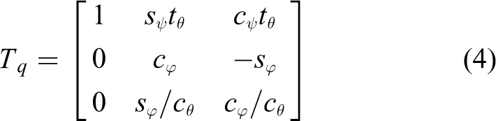
The conversion relations between the attitude angle and the flying round the body axis angular rate can be described as

where
where
State space model of quadrotor
First, define

where

where
Controller design
Feedforward compensation based on GPIO
In the quadrotor UAV system, the disturbances including model errors, parametric uncertainties, and external disturbances are time-varying. According to Taylor polynomial, it can be written as follows 19

To enhance the disturbance rejection ability, a feedforward approach is added. According to the system (5)

the GPIO can be designed as follows

where w
1, w
2, w
3, and w
4 are the estimations of x
1, x
2, d
1, and

Using the similar steps, we can obtain the estimated value of d
2, d
3, d
4, d
5, and d
6, and define them as
Remark 1
The main advantages of the GPIO are that (1) it has a higher observation accuracy in the existence of time-varying disturbances and (2) it does not depend on the model parameters, only the information of the input, output, and system order should be known. Hence, the transmit performances can be improved by introducing the estimated value
The design of composite control
In the strict feedback form, backstepping control (BSC) technique can stabilize the system by a recursive method. The recursive procedure often included two steps: (1) choosing an appropriate Lyapunov function and (2) designing the part of feedback control. By introducing the virtual control variable, it could design the satisfied virtual control step by step, and the real control output can be obtained in the final step [13].
BSC for the rotational motion
For differential equation (7), the first step we consider the tracking error

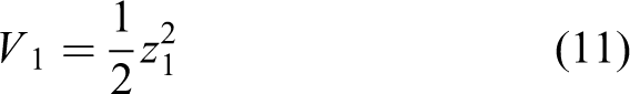
and using the Lyapunov theorem by considering the Lyapunov function z 1 positive definite
and its time derivative negative semi-definite

The stability of z
1 can be obtained by introducing a virtual control input

let

Choose Lyapunov function as

and its time derivative

So it can be conducted that U 2 should be

to make

Using the similar steps above to find U 3 and U 4

where

where
BSC for the translational motion
The attitude control U 1 can be deducted by using the similar approach mentioned above

where
According to the model (5), the motion of the axes x and y are determined by U 1. By calculating the Lyapunov function, the Ux and Uy can be computed as follows

where

where
The control principle diagram of BSC law based on the GPIO can be seen in Figure 2.

Block diagram of control system.
The stability analysis of the controller
Lemma 1 15
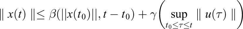
The system

is input-to-state stable (ISS) if there exist a class
Lemma 2 15
Let

where
Lemma 3 15
Consider the system (17), which is ISS. If the input satisfies
Assumption 1
For the electronic throttle system (10), suppose that disturbances satisfy
Theorem 1
If the quadrotor UAV system (7) satisfies Assumption 1 and the control law u is chosen as (17), then the disturbances of quadrotor UAV system (7) can be removed from the output channel in the steady state under the proposed GPIO-based BSC (17), on the condition that the observer parameters in (8) are properly selected such that Ae is Hurwitz matrix.
Proof
For the quadrotor UAV system, the state estimation errors are defined as

Taking the derivative of (20) and combining it with (10) and (7) together, the observation error dynamics can be expressed as follows

where

The characteristic polynomial of the observer error dynamics is then derived and given by

By selecting all the parameters in
By defining

where
It is easy to conduct that system (24) is asymptotically stable. And for system (19), the Lyapunov function of the system can be chosen as follows

where

where

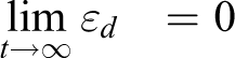
From Lemma 2, it is clear that system (24) is ISS. Meanwhile, the observation error
Simulation and experimental results
In order to validate the proposed control algorithm, BSC, BSC + ESO, and BSC + GPIO are examined by both numerical simulations and experiment in the presence of time-varying disturbances. List of the values used as model parameters are listed in Table 1. Parameters similar to the real quadrotor are selected to make a realistic model.
Parameters of the modeled quadrotor.

Simulation results
The controller parameters are as follows:
In simulations, a spiral trajectory example is exhibited. The desired trajectory is

The simulation results are shown in Figures 3 to 8. The trajectory tracking results are illustrated in Figures 3 to 5. The position tracking trajectories and tracking errors of x, y, and z axes are presented in Figures 6 to 8.

Three-dimensional flight path of the quadrotor UAV under BSC. UAV: Unmanned aerial vehicle; BSC: backstepping control.

Three-dimensional flight path of the quadrotor UAV under BSC + ESO. UAV: Unmanned aerial vehicle; BSC: backstepping control; ESO: extended state observer.

Three-dimensional flight path of the quadrotor UAV under BSC + GPIO. UAV: Unmanned aerial vehicle; BSC: backstepping control; GPIO: generalized proportional integral observer.

Tracking trajectory and tracking error of x-axis: (a) speed response curves and (b) q-axis current response curves.

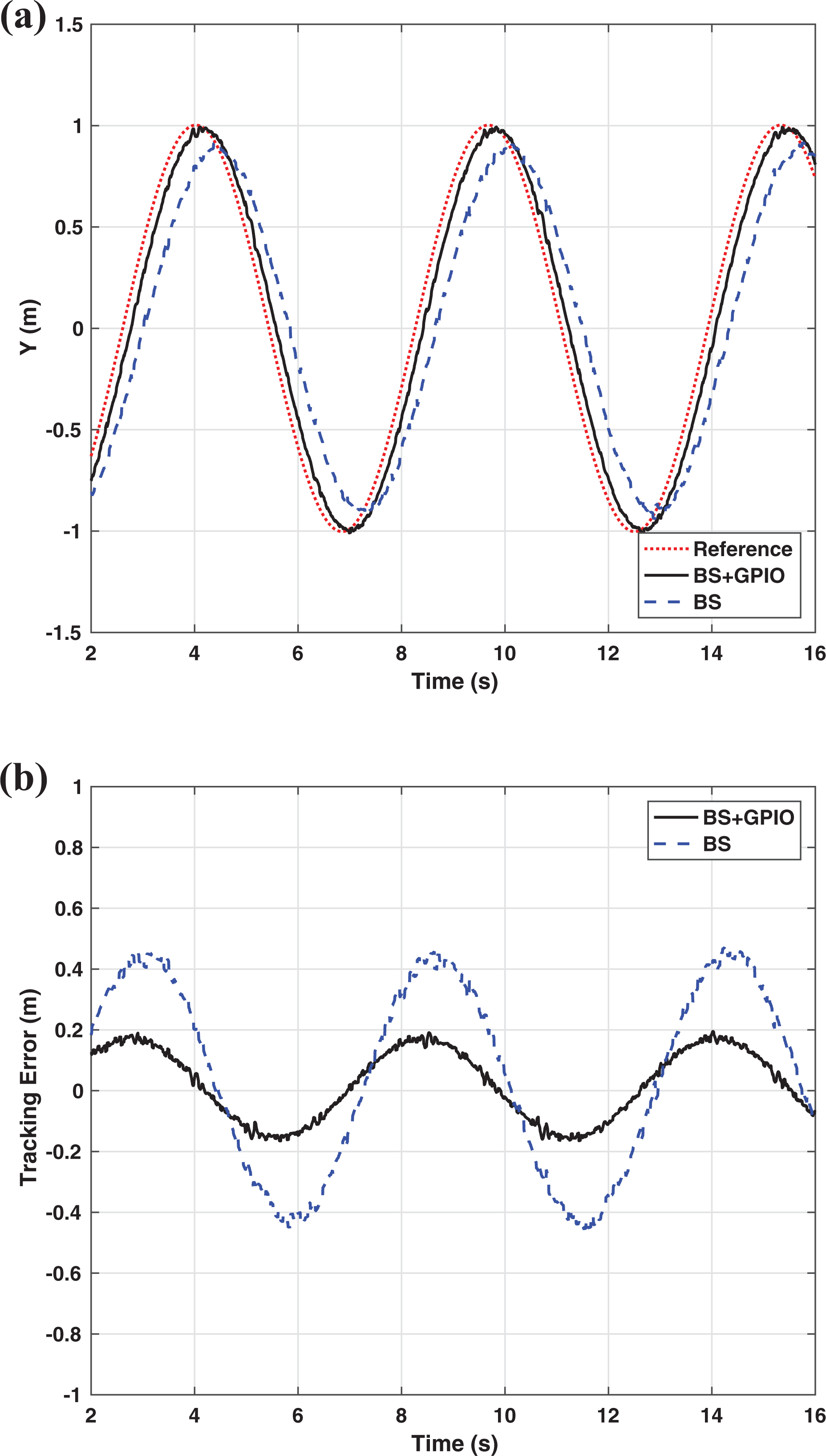
Tracking trajectory and tracking error of y-axis: (a) speed response curves and (b) q-axis current response curves.

Tracking trajectory and tracking error of z-axis: (a) speed response curves and (b) q-axis current response curves.
It can be seen from Figures 3 to 5, under the circumstance of existing time-varying disturbances, the proposed controller can drive the quadrotor UAV tracking the desired trajectory fast and accurately, which cannot be achieved by the backstepping controller. According to Figures 6 to 8, in contrast to BSC, steady-state error of GPIO-based BSC is smaller and the convergence rate is faster.
Experimental platform
Mechanical components
In consideration of durability, the body of this quadrotor uses carbon fiber as its structural material because of its high strength and light quality. Balance capacity is provided by its 500 mm diagonal axis, APC 12 × 3.8 propellers and Langyu Model Co., Ltd's SUNNYSKY-X4110S motors. In addition, rubber rings offering shock absorption are used to fix the autopilot to the body, in order to achieve a better balance.
Electrical components
TDK Group Company's MPU9250 made up of a 3-axis accelerometer, a 3-axis gyro, a 3-axis magnetometer, and an extra digital-out temperature sensor is used for pose estimation. MPU9250 provides a 16-bit high-resolution ADC for each axis, two modes of communication (I2C and SPI), and one embedded digital motion processor. Consequently, MPU9250 is a best choice. NEO-M8N is a GPS used to access location information. Meanwhile, optical flow sensor and ultrasonic sensor are selected to calculate body attitude and avoid obstacles.
A BeagleBone Blue (BBB) board which is a Linux-based computer for robotics is used as the controller of the quadrotor. The BBB integrates onto a single board the OSD3358 microprocessor, together with Wi-Fi/Bluetooth, IMU/barometer, power regulation, and so on. Moreover, remote commands are received by a 6-Channel RC receiver. Wi-Fi module also can transmit remote commands and data including sensor and camera.
Pose estimation
The body attitude of the quadrotor is estimated according to filtered data of MPU9250. Digital data collected from MPU9250 are fed to a sliding mean filter to eliminate periodic interference and get high smoothness with a small amount of CPU time.
Controller software
The flight controller software based on RT-Linux consists of periodic tasks including collecting and handling sensor data and calculating and outputting control. A ground station can be installed on client computer to view flight data, send commands, and design air line. The experimental platform is shown in Figure 9.

Structure of the overall closed-loop control system.
Experimental results
To test this further, the experiment is carried out. The controller parameters are as follows:
The real-time results with the control law of BSC + GPIO and BSC are shown in Figures 10 to 12.

Tracking trajectory and tracking error of x-axis: (a) speed response curves and (b) q-axis current response curves.
Tracking trajectory and tracking error of y-axis: (a) speed response curves and (b) q-axis current response curves.

Tracking trajectory and tracking error of z-axis: (a) speed response curves and (b) q-axis current response curves.
Figure 10 presents the sinusoid trajectory tracking curves of x-axis and tracking error under proportional derivative (PD) controller and GPIO method. Compared with tracking error of BSC (0.6 m), it can be found that the proposed BSC + GPIO algorithm has a higher tracking accuracy (0.2 m). Figure 11 presents the sinusoid trajectory tracking curves of y-axis and tracking error under PD controller and GPIO method. Compared with tracking error of BSC (0.4 m), it can be found that the proposed BSC + GPIO algorithm has a higher tracking accuracy (0.2 m). Figure 12 presents the sinusoid trajectory tracking curves of z-axis and tracking error under PD controller and GPIO method. Compared with tracking error of BSC (0.15 m), it can be found that the proposed BSC + GPIO algorithm has a higher tracking accuracy (0.08 m).
From the experimental results, the lumped time-varying disturbances are compensated by the GPIO rapidly. Hence, the position of oscillations and trajectory tracking error using BSC + GPIO are less than the ones using BSC.
According to the above results, it can be concluded that the proposed control algorithm can effectively suppress the lumped time-varying disturbances and provide better trajectory tracking performances.
Conclusion
In this article, a robust tracking design method for quadrotor UAV has been proposed to enhance the ability of disturbance rejection in case of multiple sources of time-varying disturbances. Firstly, a GPIO is introduced to observe the lumped time-varying disturbance, and a corresponding disturbance feedforward compensation part has been designed. Secondly, a BSC technique is applied in the feedback design. The proposed method can be seen as a composition of BSC and GPIO. Compared with BSC, the proposed method has greatly improved the tracking performance and the robustness against multiple sources of time-varying disturbances by both simulation and experiment.
Footnotes
Declaration of conflicting interests
The author(s) declared the following potential conflicts of interest with respect to the research, authorship, and/or publication of this article: The authors declare that they have no financial and personal relationships with other people or organizations that can inappropriately influence their work. There is no professional or other personal interest of any nature or kind in any product, service, and/or company that could be construed as influencing the position presented in, or the review of, the manuscript entitled “a generalized proportional integral observer–based robust tracking design approach for quadrotor unmanned aerial vehicle.”
Funding
The author(s) disclosed receipt of the following financial support for the research, authorship, and/or publication of this article: This research was funded by the Natural Science Foundation of the Jiangsu Higher Education Institutions of China, grant number 19KJB510033.