
Abstract
In this article, a design of honeycomb structure–based soft continuum manipulator is proposed to achieve higher structural strength while keeping compact layout, low material consumption, and thinner wall. At first, a pneumatic deformable cell is designed to simulate the beehive hexagon structure. Secondly, cell units are combined together in a parallel way to form the body module whose stiffness is increased. Thirdly, a gripper module is designed based on the combination of the cell units in one end. Fourthly, several body modules and a gripper module are serially linked to form a soft robot. Fifthly, the basic kinematics of the module is modeled and analyzed. Finally, a prototype made up of silicone rubber is developed for experiments. In the experiments, the soft robot managed to pick up a ball and an egg. The quantitative experiments show that the maximum bending angle was about 90°, and the maximum extending ratio approaches 1.7:1 for a three-module robot test. Reliability test shows a good behavior even though the robot lost its 50% cells. The results show that the new design idea, which is inspired by the cell in biology, is available to improve the reliability of soft robot as expected and enables the robot to move with good flexibility.
Introduction
S
Force/torque sensor: The first effort is to install force/torque sensor on the robot hand or gripper. When unexpectedly touching people, there will be big changes in the sensor, then the robot controller may know that an unexpected collision has occurred. However, the collision may occur on the arm, not the hand. Furthermore, when a collision is detected, it has happened. Although infrared or sonic distance sensor can be utilized to avoid collision, it is impossible to be mounted all the robot body surface. Stiffness/impedance adjustable robot: In these robots, the stiffness/impedance of the driven joint can be adjusted, thus it acquires flexibility when touching people. The passive robot or underdriven robot can also be categorized into this type. When unexpected collision occurs, the passive joint or underdriven robot can absorb the impact.
5
However, this will result in uncertainty and complexity in motion control. Hyperredundant robots (or snake-like robots): By configuring multijoints (generally more than 6) in the body, the robot can acquire mechanic flexibility during motion. Thus, it has high environment adaptability. These robots usually consist of many joints of DOFs connected by rigid links,
6
such as trunk-like manipulator
1,7,8
and manipulator by jamming of granular media.
9
However, hyperredundant robot is complex in motion control. Robot with flexible driven or flexible part: One way is to wear soft cover on the hard robot, like Pebble.
10
The other way is to use flexible driven or flexible link in the robot. SMA or cable has elasticity, and they can deform to absorb impact during collision, thus making the robot “soft,” like SMA-driven robot
11
–13
and cable-driven octopus tentacle.
14
OctArm is a soft manipulator worked with pneumatic artificial muscles (PAMs) which can withstand a large payload. However, restricted by shape and working characteristics of PAMs, OctArm’s structure is not flexible enough and cannot stretch.
15,16
While in gecko-like robot, it applies elastic link in the robot thus making it soft.
17
Robots made up of soft material: Soft material is the key and the important difference between the soft and the hard.
18
It is an intelligent bionic artificial material, which has biologically soft and deformable features and can withstand large strain.
2
Robots can better reproduce the properties of the natural organisms with soft material.
19
Because of these, soft robots have been an interesting research aspect for its continuous deformation, high adaptability, and high safety. Researchers have developed many kinds of soft robots. Shepherd et al. made a quadruped soft robot using Ecoflex® material and accomplished walking functions.
20,21
And later they changed the quadruped structure into a four-finger claw or three-finger claw to grasp objects.
22,23
In their design, the feet or fingers can bend but cannot stretch. Correll et al. design an inchworm soft robot with pneumatic drive using Ecoflex material,
24
which can extend and bend, thus has more movement flexibility. Martinez et al. build a pneumatic soft tentacle using Ecoflex and PDMS, thus to grasp an object by winding on it like a trunk.
25
Marchese et al. and Cianchetti et al., respectively, make a soft manipulator with a similar structure of pneumatic soft tentacle made by Martinez et al.
25
using the same material.
26,27
Shanghai Jiao Tong University made a modular soft robot using ordinary rubber, which moves like a caterpillar.
28
But its structure is rather simple to achieve complex motion.
Generally, soft robot is prone to be broken down, and the reliability of traditional design with pneumatic drive is rather low, that is, while one of its chambers leaks, the robot cannot work. Therefore, a new design is demanded to improve the soft robot’s reliability. In addition, soft robot made up of Ecoflex material is rather soft, which can just move or grasp small objects. Robot should be soft for safety, but it should not be so soft when performing tasks. Therefore, the soft robot should have enough structural stiffness to perform tasks.
The cellular hexagon structure enables the honeycomb high structural strength while keeping compact layout, low material consumption, and thinner wall. The hat and lantern shown in Figure 1 are made up of soft paper and can deform easily. However, they can keep their shape in some extent of structural strength due to beehive structure.

Beehive-structure-based paper hat and lantern.
Inspired by the beehive structure, which consists of many same cell units with least material but achieve maximum structural strength, a new design of modular soft robot is proposed which is based on beehive structure. Firstly, a cell is designed which simulates the beehive hexagon structure. The cell can deform under pneumatic drive. Secondly, body module and gripper module are developed by consolidating many cell units to increase the motion, reliability, and stiffness. Thirdly, several modules are linked to form a soft robot. The number of modules can be changed according to the necessity. A simple kinematic model is also proposed for simple control. To verify the validity of the design, a prototype is fabricated with silicone rubber. The qualitative and quantitative experiments indicate that the proposed design is feasible and valid. Some of our previous work has been introduced in IROS 2015. 29
Our contribution of this article is mainly about the following: (1) Beehive cellular hexagon structure is introduced into design, which improves the reliability and the structural stiffness of the soft robot. (2) Body module and gripper module are designed. The hexagon cells are consolidated to form body module and gripper module. These modules can generate the basic motion for the soft robot, such as extension/extraction, bending, and grapple. (3) A prototype has been fabricated with silicon rubber with cast method. Some qualitative and quantitative tests are implemented to verify the design. The tests show the basic characteristics of the soft robot and verify its advantage that the proposed soft robot can still work even if it loses its 50% cells.
The rest of the article is organized as follows: We begin with the manipulator’s structure design in the second section, which is the most important part in our article. Third section proposes a simple kinematic model. Fourth section introduces a prototype based on the general characteristics in the second section. Fifth section introduces tests and analysis, followed by the sixth section discussing some further problems. The final section concludes this article.
Structure design
Overall structure
In beehive structure, hexagon is prone to deform; however, hexagon can be tessellated that they are mutually connected in a compact way, which makes beehive a stable shape.
Inspired by this, a soft robot is designed, as shown in Figure 2. The soft robot consists of five body modules and one gripper module. Each module consists of many same hexagon cell units which are arranged in beehive way.

Snapshot of the proposed soft robot.
Cell unit design
Hexagon cell is the smallest structure unit, and its tessellation will make the structure more compact and stable.
Figure 3(a) shows the linear sketch of the hexagon cell, Figure 3(b) the three views of the engineering design, and Figure 3(c) the schematic deformation.

Illustration of cell unit: (a) linear sketch; (b) three views of engineering; (c) schematic deformation.
Figure 3(a) shows that the hexagon cell is a hexagonal prism with its inner space a cavity for air. The cavity enables the hexagon cell that can be pneumatic driven to deform. Figure 3(c) shows the initial state and the deformations of a hexagon cell in normal shape, contracted shape after air exhaust, and extension shape after inflation. Since the cell can deform, the front and back walls need to be deformable. To fulfill this, the front and back walls both consist of six triangles which are in different planes, and these triangles eventually construct a special hexagon which can deform like a foldable trusses. From Figure 3(c), it can also be seen that the height change is dependent on the cell’s back wall, because it will arrive at its extreme at first.
In the initial state, the two opposite interior angles of the hexagon cell are 60°, with the other angles 150°. With such configuration, the cell may have roughly equal strokes when be extended or compressed (as shown in Figure 3(c)). The cell is designed like fan-shaped, as shown in Figure 3(b). This design enables them to be connected into a circular shape. The rim between the hexagons and the upper / lower wall is made round corner to avoid stress concentration.
Body module
For only one hexagon cell, it can only have extension or contraction motion. For two columns of adjacent hexagon cell groups, they can have bending motion except extension motion and contraction motion by adjusting the air pressure in each column, as shown in Figure 4(a). If a manipulator consists of such groups, then complex motion can be generated by synthesizing these motions.

Body module design: (a) deformation of cell groups, (b) stiffness of different configurations of cell groups, (c) body module consists of n × m cells, (d) schematics of body module configuration and deformation.
Elephant nose is well known for its flexibility and dexterity. Its cross section is round; therefore, it is plausible to choose cylinder as the basic geometry for manipulator. Furthermore, its axial symmetry makes it convenient to construct arbitrary spatial configuration of manipulator and feasible to arrange these hexagons on the lateral surface of cylinder as shown in Figure 4(b).
The body cylinder can be supported by sparse layout of the columns of hexagon cells, shown as the right figure in Figure 4(b). Although the sparse arrangements need less cells, obviously it has low stiffness (especially antitorsion). Therefore, dense arrangement is preferred for its good stiffness, as the middle in Figure 4(b).
Module layout
According to the dense arrangement, a module consists of m layers with n cells in each layer, as shown in Figure 4(c). The m layers are staggered in arrangement, which makes the upper wall of the lower layer becomes the lower wall of its upper layer, and vice versa.
Obviously, this layout is compact, each cell units mutually sustain, and there is no null interspace between them. This arrangement saves material and exhibits advantages of structure stability, lightweight, flexibility, and torsion resistance.
Cell length
The hexagonal prism cell unit is fan-shaped, so the area of back wall is smaller than the front wall, thus while they expand maximally, the distance between the upper and lower wall will be larger at the front side. In extreme case, if the cell length approaches the module’s radius, then the back wall cannot expand/fold or just can expand/fold in a very small range. In this case, module’s movement ability and flexibility will be significantly impaired. To avoid this situation, under the consideration of the front and back wall’s design, shorter cell length is better for module’s movement ability and flexibility.
Chamber connectivity
Since each body module has n × m cells, there will be n × m cavity chambers. It is hard to pneumatic drive these chambers individually, neither the physical connection nor driver will be complex. Therefore, these chambers are divided into three groups, and each group is connected through small eyelets in the interval wall, as shown in Figure 5. The inner walls are still kept to ensure its antitorque stiffness.

Triple groups of connected chamber.
With such a design, the body module still can have motions of extension, contraction, and bending, as shown in Figure 4(d).
Structure interference
For real cells, the thickness in the wall is neglected for scheme, but it will result in structure interference since the deformations of the interior side and exterior side of the wall are different. For this interference, flexible elastic material is utilized whose elasticity can eliminate or adapt to the structural deformation interference.
Gripper module
Generally, gripper is one part of robot. Especially in soft robots, flexible passive grapple is a useful way to reduce cost.
Figure 6 shows the cell-based soft gripper module. The soft gripper consists of a central part and three fingers. Each finger consists of four cell units (the number of cells in each finger is determined by bending radius required). The central part contains some chamber which connects eyelets of these fingers.

Soft gripper with triple fingers.
To make these fingers bend, the inner sides of back walls are filled up with silicone rubber. When air is inflated into the central part, all front walls of these fingers will expand simultaneously, while the fillers prevent back walls to expand. Thus, the fingers are bended for grasp motion.
Module connection
The robot shown in Figure 2 consists of five body modules and one gripper module. The modular design enables the robot to change its structure easily or change new part easily. To connect the body module, a docking joint is designed to combine different number of modules along axial direction.
A docking joint consists of a pair of mortise and tenon which can be used to connect or disconnect the modules conveniently, as shown in Figure 7. On the interface between two modules, there are n pairs of such joint, which are uniformly distributed along circumferential direction on the bottom and top surface of the modules. These joints will be locked by elastic force along the radial direction of the module. The elastic force is due to the relative position of these joints, which can be adjusted during the initial assemble. This design reduces docking joints’ weight and brings convenient installation.

Docking joints.
Basic kinematics
As previously mentioned, each body module is divided into three big single chambers, denoted by A, B, and C, respectively. There exists a definite relation between the total length of these chambers and their chamber pressure. As shown in Figure 8, we define the middle line on the big single chamber’s outer surface along the axial direction of the module as the total length of the single chamber, denoted as

λ, α, and θ to indicate the module state.
As shown in Figure 8, three parameters, α, λ, and θ, are used to portrait the kinematic position of the module in the rectangular coordinate system. O and O′ are, respectively, the geometrical center of the bottom and top surface of the module, and O is the origin of the rectangular coordinate system. Assuming that the backbone
Under the above assumption, it is not difficult to deduce the following relations

where L is the initial height of the body module in normal state. While for the position of O′ (x, y, z) in the coordinate frame O-xyz, it can be worked out as follows

If we want to control O′ to move to (x, y, z), then from equation (2)
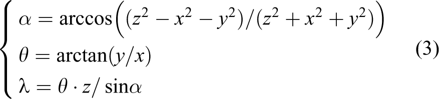
According to above, the coordinates (x, y, z) can be used to change the length of AA′, BB′, and CC′. The motion attitude of the module can be controlled based on this relationship.
Some similar and more efficient models can be found in previous works. 30
Prototype
To verify the design, a prototype of the soft robot as shown in Figure 2 is developed.
Structure parameters
In the developed robot, five body modules and one gripper module are employed. For each body module, Has a height of 600 mm and diameter of 100 mm. Consists of seven layers with six cells in each layer, totally 42 cells. Has a cell length of 25 mm. The shorter length is the better, but the minimum length should ensure that cell’s front and back walls won’t intervene; 25 mm is appropriate for our module dimension.
To let the deformation mainly along the direction vertical to the upper and lower walls, different thicknesses should be set in the upper/lower wall and front/back wall, that is, upper/lower wall should be thicker than front/back wall. With this configuration, the change in pneumatic pressure will result in bigger deformation in thinner walls than in thicker walls. In our prototype, we choose that the minimum thickness of the front and back walls is 1 mm, and the thickness of the lower and upper walls is 1.5 mm.
For our body module, the 42 cells are divided into 3 groups of connected chambers, each group containing 14 cells (120° circumferential distribution, as illustrated in Figure 5).
To enhance the reliability, each group of connected chambers is equally divided into two small subgroups. Each subgroup contains seven cells and one vent. The two vents of the same big group are connected together by Y-style tube joint, which means the two subgroups share the same air pipeline driver.
Fabrication
To fabricate the prototype, the materials should be selected at first. Material is the significant difference between hard robot and soft robot. In our prototype, Dow Corning GP silicone sealant is adopted as the basic material due to its large elasticity. It can be turned into elastic silicone rubber through reacting with moisture in the air after solidification at room temperature. GP is an acid-curing silicone sealant, and Table 1 shows its physical properties. After solidification, it has high tenacity and can bear pneumatic pressure about 0.5–1.2 MPa.
Physical properties of silicone sealant.

aUltimate tensile strength and movement capability are measured in 7 days after curing.
The cell unit’s structure is complex. In order to fulfil this complex shape with the silicone rubber casting molding is employed. At first, a 3D mold model is acquired by 3D printing. Since the minimum thickness of cell wall is about 1 mm in the prototype, the 3D printer should undertake the shape’s completeness.
It is difficult to fabricate each cell one by one. Hence six cells are fabricated in a layer simultaneously. Then seven layers are stuck up one by one to form a body module.
The molds and the fabrication process are illustrated in Figure 9.

Fabrication procedure.
For the gripper module, one layer of silicone rubber with walls and another without walls are fabricated. Then they are stuck up and cut into single cell units. After sticking these single cells into the shape as shown in Figure 5, the finger and gripper can be acquired.
Pneumatic driven system
For every body module, the chamber groups are denoted by A, B, and C, respectively. For every chamber group, there are a vacuum pump and air pumper connected with them, as shown in Figure 10. In Figure 10, V i (i = A1, A2, B1, B2, C1, C2) are electromagnetic valves, which are controlled by Relay modules to turn on or off the air pipeline. P j (j = 1, 2, 3) are pressure sensors to sense the air pressure in chambers A, B, and C, respectively. The pumps and valves are controlled by an MCU (Arduino Mega 2560).

Pneumatic driving and control system.
For different body modules, different pneumatic drivers and controls are required. For gripper module, only one air pipeline is required, since its motion is only to clasp or to unclasp.
A high-level PC is employed to coordinate all the module’s control. By differentiating motion parameters for different modules, complex motion can be formed for the soft robot.
Figure 11 shows a prototype of the body module, with 60 mm height and 100 diameter, containing 3 big single chambers and 3 Y-style gas joints; 6 small single chambers and 6 vents. Forty-two cell units are tessellated to form a cylinder leaving a tunnel along the axial direction. Pneumatic tubes can be deployed through the tunnel, and such layout makes the module looked less messy. Something more, each big single chamber has two vents for air supply, converting the pressure energy to relaxing and contracting motions. Vents locate on the inner wall of cylindrical module, connected with the external tubes.
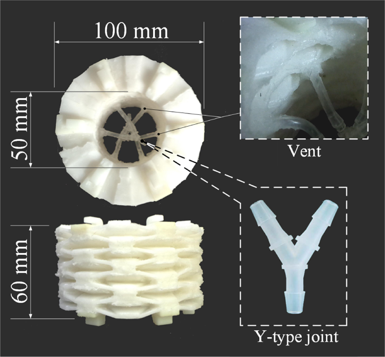
Prototype of a body module.
Each big single chamber contains 14 cell units and 2 vents. We use three Y-style joints to connect the six vents (one joint connect the two vents in the same big single chamber), eventually there will be three gas tubes in a module. Figure 12 shows the basic motions of the body module: bending, contraction, and extension. Table 2 shows the basic parameters of the body module.

Basic motion of body module.
Body module parameters.a

aThe above data are measured under gravity environment.
Experiments and analysis
To verify the design, qualitative and quantitative experiments are conducted with the developed prototype.
Qualitative tests
In the first experiment, three body modules are connected to form a soft manipulator, with an electromagnet as end effector.
The soft manipulator is hung in the air and is successfully controlled to stretch to pick up a polygon paper ball which has a stuck coin for magnetic suction and then to transit the ball into a box, as shown in Figure 13. In the test, it can contract to the minimum or stretch to the maximum length. The maximum expansion ratio reaches 2:1. The maximum bending angle is up to 85°. It is less than the accumulated maximum bending angle or three modules; this is because the gravity offset some bending torque.
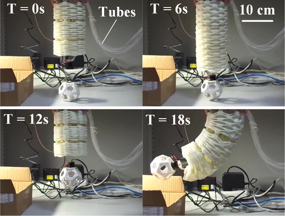
3-Module test.
In the next test, the manipulator is made up of five body modules and one gripper module.
The similar task is conducted, except that the ball is grasped by the soft gripper, as shown in Figure 14. With self-adaptability of the soft gripper, when in contact with the paper ball, the grasper can achieve compatibility with it by passive deformation. This means that the soft gripper can pick up fragile objects without pressure sensor. In this test, the maximum expansion ratio decreased to 1.6:1; the bending angle reaches about 105°. The deduction is resulted in the addition of undeformable docking mechanism. The gravity of modules will affect the gas volume and increase the deformation deviation.

5-Module robot test.
Gravity affects the performance of the designed soft manipulator. Therefore, it is tested in the microgravity situation, that is, in a water tank. The soft manipulator is sunk in the water to allow the buoyancy to counteract some gravity. In this environment, the manipulator can construct “S” configuration, which exhibits a good flexibility. Figure 15 shows the test to pick up an egg. Since the gripper can deform passively, it succeeds to pick up the egg easily, which shows the significant characteristic of the soft manipulator.

Grapping a duck egg in the water.
Quantitative tests
For quantitative tests, three-module manipulator is used.
Extension test
Total length is used to indicate the extension state of manipulator. The three groups of chambers are inflated or deflated simultaneously. The correspondence between length and air pump pressure is shown in Figure 16. The original length of three modules is 180 mm, but in the experiment, its original length decreases to 160 mm due to the gravity.

Relation between length and pump air pressure.
From the curve, maximum extension ratio (MER, the ratio of maximum length to minimum length) is about 1.69:1. The length variation has a nearly linear relation with pump pressure when pressure is in −3 to 9 KPa. Out of this range, the chamber space has reached its deformation extreme, and other variation mainly is due to elastic deformation of the material itself.
Bending test
To make the body bend, there are two ways: one is to inflate two groups of connected chambers (denoted by two active eay, TAW) and the other is to inflate just one group of connected chambers (denoted by one active way, OAW), as shown in Figure 17. In the figure, the abscissa is the air pressure where the noninflated chambers are deflated to −30 KPa air pressure.

Relation between bending angle and air pressure.
From the figure, we can see that the maximum bending angle reaches 95° when two groups of connected chambers are inflated to 12 KPa. When only one group of connected chambers are inflated to the same pressure, the maximum bending angle is about 70°, 26% lower than the former.
This difference is because there are more cells involved in extension in the TAW (66.7%) than in OAW (33.3%). Therefore, in OAW, more air pressure should be required for the same bending angle in TAW. Furthermore, it should be noted that the bending directions for TAW and OAW are different in these situations.
Reliability test
The body module consists of many connected hexagon cells, and these cells are divided into three groups of connected chambers or six subgroups of connected chambers. If any cell is broken down, then its subgroup connected chamber can be cut off for isolation. The other chambers can ensure the body function normally.
In the reliability test, we simulate the cell malfunction by turning off some valves. Figure 18 shows one of the tests. In the figure, the “red” indicates the malfunctioned subgroup, while the “green” indicates the normal. In the extension test, we can see that the extension curve is similar to the normal case except that there is a decrease in A chambers. This is due to the malfunctioned subgroup in A lies in the bottom. Therefore, less cells can be employed to support its upper module weight. In the bending test, we can see that there is also a decrease in the bending angle. This shows that in case of malfunctioned cells, more driven force should be provided. However, the robot can still extend or bend as expected, which indicates that the cell-based robot has higher reliability than normal robot. The test shown in Figure 19 verifies this conclusion again, where there are 50% cells are lost but symmetrically distributed. The only impact is that there is obvious decrease in the expansion or bending during inflation at the same pressure as normal case.
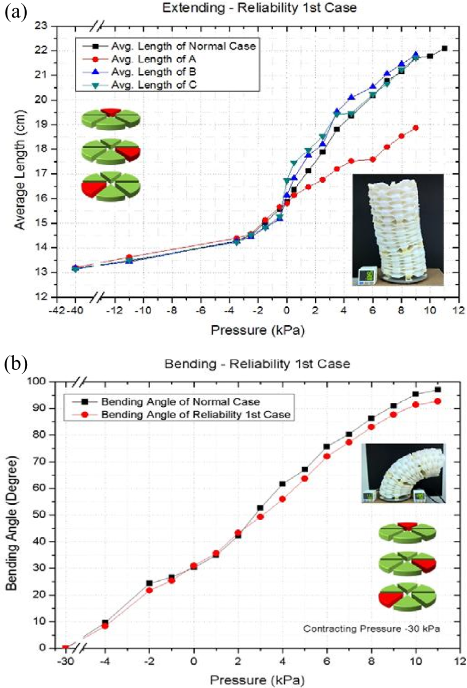
Reliability test 1: (a) extension test and (b) bending test.
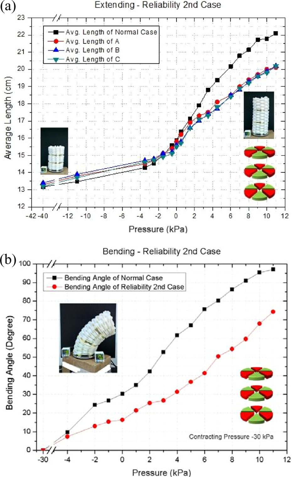
Reliability test 2: (a) extension test and (b) bending test.
Table 3 shows the quantitative characteristic of the manipulator after quantitative test.
Manipulator size and motion parameters.a

aThe above data are measured under gravity environment.
Discussion
In this article, a soft robot is developed with soft material and is managed to pick up fragile objects by pneumatic drive. But there are still some issues to be further improved.
In the qualitative experiments, the soft manipulator is hung in the air, while in the quantitative experiments, it is fixed vertically on the ground. In the two different configurations, the gravity has different influence. To summarize, the gravity has impact on the performance of the soft robot. In fact, in soft robotics, the stiffness and the flexibility contradict each other. Therefore, to find a better balance between them, further optimum in raw material selection and structure design is still a significant research direction in the future. For example, hybrid hard and soft material may enhance its adaptability, by utilizing hard but light material as skeleton while soft material as body cover.
Except the material, the structural parameters of the prototype, such as wall thickness, may not be the most reasonable. More works should concentrate on how to reduce the weight, for example, the thickness of the inner wall of a body module should be decreased. Due to the constraints of current fabrication technology, it is two times as thick as the top wall. If 3D printer can be utilized to print the soft robot directly with miscellaneous material, it can have better performance.
Furthermore, in the experiment, the soft robot is under manual control. In order to function autonomously, more works are required: (1) Control loop should be closed. The robot controller should sense its state and position; (2) more kinematics and inverse kinematics model should be developed; (3) kinematics parameters should be calibrated.
However, the experiment can verify that the beehive-structured modular soft robot is a valid design. It shows the advantages of both modular design and cell design. Even if some cells are broken down, the soft robot can keep function similarly. It also shows advantages in grasping fragile objects through passive deformation without requiring precise force feedback control.
Conclusion
In this article, a new design of soft manipulator is demonstrated, which is inspired by the cell in biology and beehive structure. In biology, organ consists of cells and body consists of organs. When few cells are broken, the body can still work. While in beehive structure, hexagon cell makes the beehive firm but compact and light.
Inspired by these advantages, a deformable hexagon cell unit is developed. Based on the cell unit, body module and gripper module are developed by compact and ingenious layout. Then its basic kinematics is set up and analyzed. Its pneumatic driven and simple control are devised too. Finally, a prototype is developed with silicone rubber.
To verify the feasibility, some experiments are conducted. In the qualitative experiments, the soft robot was controlled to pick up a ball and an egg. This shows the flexibility and feasibility of the soft robot. In the quantitative experiments, the maximum extension ration and bending angle are tested. In the three-module case, the exact MER is 1.7:1 and the maximum bending angle is about 97. Furthermore, the reliability of the soft robot is also testified by simulating cell unit malfunction. The test results show that even the manipulator loses its 50% cells, it can still work to some extent.
In summary, the new design helps to improve the reliability of the soft robot, it can achieve continuous deformation. The experiment shows that it has potential in some tasks which soft touch and grapple are demanded, such as space object grapple.
Footnotes
Acknowledgements
The authors thank Sheng Zhang and Zuohao Hua who contributed their efforts in the control system’s design and manufacture in the previous research progress.
Declaration of conflicting interests
The author(s) declared no potential conflicts of interest with respect to the research, authorship, and/or publication of this article.
Funding
The author(s) disclosed receipt of the following financial support for the research, authorship, and/or publication of this article: This work was supported in part by the Fundamental Research Funds for the Central Universities under Grant No. YWF-14-YHXY-015.