
Abstract
Aiming at the problem of apple branch obstacle localization in fruit picking process of harvesting robot manipulator, in order to obtain three-dimensional information of the apple branch obstacle, the binocular stereo vision localization method of apple branch obstacle is proposed. Firstly, branch skeleton is extracted by morphological thinning method and then the feature skeleton is obtained after removing the false branch and recovering the occluded branch. After that, the endpoints and bifurcation points regarded as match feature points are extracted from skeleton, and the stereo matching algorithm based on features is adopted. Then, the depth information of branch obstacle is obtained on the basis of triangulation theory. Finally, the experiment results for apple tree branches localization show that the error lies in ±6.2 mm. Moreover, the error is merely ±1.5 mm when the distance between the object and the binocular camera is 1000 mm, which meets with localization accuracy requirements of apple harvesting robot visual system.
Introduction
The perception of fruit tree branches plays a very important role in obstacle avoidance and fruit picking process of harvesting robot manipulator. If a robot cannot identify the branch obstacles efficiently, the robot manipulator may collide with the obstacles and destroy itself as well as the fruit trees. Therefore, the accurate positioning of branch is one of the key techniques in the obstacle perception of fruit harvesting robot. In our prior research of branch recognition, 1 we mainly focused on identifying the two-dimensional space of branches and did not included the depth information of branches. This work is different from the above 1 in that it focuses on branch localization including depth information based on the branch recognized.
At present, several research about trees’ three-dimensional (3D) modelling and fruit localization are available. 2 Shlyakhter et al. and Liu et al. 3,4 paid attention to the study of 3D modelling of trees based on L-system without combined research with robot obstacle avoidance. Meanwhile, Si et al. 5 researched about localization of fruit by a matching algorithm based on area and epipolar geometry to locate the apples. The apples with similar areas were matched according to the principle of ordering constraint by calculating the maximum value of cross-correlation function of vertical projections. Arefi et al. 6 researched about tomato localization using morphological features of images. In order to solve the problem of low localization accuracy which results from the rough edge of apples after segmentation, a new method based on a contour symmetry axis was proposed to locate the picking point of apples. 7 Bac et al. 8 researched about stem localization of sweet pepper plants using object-based and 3D features and minimum expected stem distance. From these references, the fruit and stem localization are usually a solution of the single point coordinates. However, branches are more complex than fruit and stem. Moreover, the branch including certain angle and length is irregular, and the single-point localization for a branch cannot fully display the whole branch localization. The branch localization and 3D reconstruction were studied by Cai et al. 9 The 3D information of branch diameter and length was given in the experiment, but the depth distance of the target was not verified.
The branch can be regarded as the connection of many feature points which perform the structure of the branch, and therefore the localization of these feature points can represent the localization of branch. According to earlier studies, 1,10 –12 it is difficult to process stereo matching of the branch images because of the large number of image pixels which are not only various but complex. In this condition, it is necessary to extract the related parameters of the corresponding feature regions or the feature points of two images as the characteristic parameters of the stereo matching. As the actual shape of the branch is cylindrical, the entire branch can be viewed as a section of the cylinder spliced; the centre and radius of each cylinder determine their location and size, so the centre position and the radius of a cylinder branch are crucial characteristic parameters for trees.
To obtain the skeleton of branch, this article firstly extracts the axis of the branch; segments the skeleton with endpoint, branch point, and other feather points; and recovers 3D space information of branch according to the feature that branch is cylinder spliced. Then the stereo matching algorithm based on the feather is adopted. Finally, the depth information of branch obstacle is obtained on the basis of triangulation theory.
Materials and methods
Skeleton feature extraction for apple tree branch
Skeleton of branch
Skeleton S(A) is a collection of all points that can be tangent with the boundary outline of A (at least two points), setting any point in the binary image as the centre of a circle, and it can be obtained by dealing with the binary image A with morphological erosion and open operation. 13
Adopting the morphological thinning method, the branch skeleton is shown in Figure 1. It is obviously seen that this method can not only keep skeleton image connective and meet single pixel but also reduce the amount of computation greatly due to merely dealing with the target area. However, this method produces more false branch, which has a profound impact upon the target matching. So further skeleton pruning is required.

Branch morphological thinning image.
Skeleton pruning
The main reason for the generation of false branch is that the edge of the recognized binary image is not smooth due to some small bumps.
1
The following definitions are proposed before the skeleton pruning:
Endpoint: There is only one skeleton point among eight neighbourhoods of the skeleton point p.
Bifurcation point: There are at least three skeleton points among eight neighbourhoods of the skeleton point p.
The steps for removing false branch are as follows: Step 1: The number of skeleton point is counted among eight neighbourhoods in the skeleton image obtained by morphological thinning, if the value is 1, the skeleton point is endpoint, if the value is greater than or equal to 3, it is bifurcation point, and all points are recorded, respectively. Step 2: All the eight neighbourhoods of bifurcation points are turned into zero, meanwhile the branch is disconnected from the main branch. Step 3: If two endpoints of this branch are bifurcation points recorded in step 1, this branch is the main branch. It cannot be cut off, turning to step 8. Step 4: If two endpoints of this branch are endpoints recorded in step 1, this branch is an independent skeleton segment. It cannot be cut off, turning to step 8. Step 5: If two endpoints of this branch are the endpoint and bifurcation point, respectively, recorded in step 1, this branch is the true branch. Step 6: The eight neighbourhoods for each skeleton point of the true branch are marked, and the total number of pixels of each branch is counted, thus get the pixel length of each branch. Step 7: Setting the threshold as 5 pixel length, comparing the length of each branch with the threshold, if the length is smaller than the threshold, the branch is removed. Step 8: Covering removed bifurcation points, turning to step 3, until all the bifurcation points are recovered.
The final skeletons are shown in Figure 2 after the above steps are taken.
Skeletons after removing false branch.
Recovery of occluded branch
In the process of the branch recognition, one branch may be divided into two segments or even more due to the existence of shields. The shields can be the leaves on branch, or the fruits on branch, there may be branches in the disconnected part, if the harvesting robot ignores the branch which is occluded by leaves, it will lead to the damage of manipulator and the failure of picking process. Meanwhile, branch is occluded by the fruits, but it is unnecessary to recover the occluded branch, as the aim is to pick apples. However, under some special situations like two apples are close and located behind and front of branch are hard to tackle. If the two apples are picked orderly, it will result in failure of picking process due to the branch obstacle cannot be avoided in time. So no matter in any situations, it is necessary to recover the occluded branch. In this article, linear Hough transformation is adopted to obtain and cut the skeleton line and recover the occluded branch.
14
Obtaining for skeleton line
Scanning the occluded skeleton image along the x-axis by line and recording the pixel points whose value is 1. Defining the top left of the image as the coordinate system origin, turning Cartesian coordinate system (x, y) into parametric coordinate system (r, θ) according to the Hough transformation, setting the pixel point as a starting point, drawing a ray every degree in a counter clockwise direction from 0° to 360°, calculating the distance r from each ray to the origin and the angle θ between the normal of each ray and x-axis. Equation (1) is adopted to calculate the r to avoid the slope of ray perpendicular to x-axis is infinite, the value of r and θ are stored in matrix M(r, θ), counting the number of every M(r, θ), the requested line consists of the point that most frequently maps to Cartesian coordinate system. The corresponding line is shown in equation (2)


The line calculated by the above step is shown in Figure 3, and the most frequent parameter coordinate (r, θ) used 62 times is (333, 80). The linear equation is
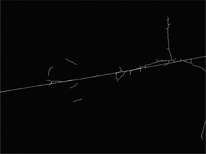
Linear Hough transformation on branch skeletons.
Cutting for skeleton line
Meanwhile, the line obtained by Hough transformation permeates the entire image, and the main steps about cutting are as follows: Step1: Counting the number of eight neighbourhood pixel points of the point whose pixel value is 1 in Figure 3 and recording the point whose value is greater than or equal to 3. Step 2: Counting the number of eight neighbourhood pixel points of the point whose pixel value is 1 in Figure 2 and recording the point whose the value is greater than or equal to 3. Step 3: Comparing the points recorded in steps 1 and 2, finding out the extra points, and recording them. Step 4: Finding out the points recorded in the previous step in the image of skeletons after removing false branch, turning it and its eight neighbourhoods into 0, and copying it to Figure 3, and then the line is cut off. Step 5: Counting the pixel point in eight neighbourhoods of every pixel point in the line, marking the point whose value is 1 as P, cutting off the line if two endpoints of line are all P.
After the above process, result of the occluded branches recovery is shown in Figure 4.

Result of the occluded branches recovery.
The extraction of branch radius
The eight neighbourhoods of each skeleton point in Figure 4 will be counted with the endpoint and the bifurcation point achieved in the previous section. If the value is 1, the point is endpoint. If the value is greater than or equal to 3, it is bifurcation point, they are also marked along x-axis line by line. These points will be used in feature matching as feature points later. During the picking process, if the branch is viewed as a plane and its thickness is ignored, it is highly possible for the picking robot to collide with the branch obstacle. The space information of branch obstacle will be obtained by calculating their radius after treating the skeleton point between feature points as centre. The radius is calculated by acquiring branch distance transformation image which is acquired as follows. 15,16
Firstly, image A (pixel resolution M × N) is scanned along x-axis line by line in forward direction, the position of point, whose pixel value is 1, is recorded as (xi
, yi
) (1: target, 0: background). O is the collection of all target points:


Distance transformation image of branch.
According to the distance transformation image, the branch skeleton is consisted of maximum distance between the target point and the boundary in the branch binary image, therefore the value of these points is the radius of the branch in this point. So, R is all the maximum distance between two feature points in a branch

where S is the collection of skeleton points between two feature points, d(p) is the distance value of skeleton point p and N is the total number of skeleton points between two feature points. Because the skeleton of occluded recovery branch is not displayed in distance transformation image, thus the distance value of this part of the skeleton cannot be directly obtained. In fact, the radius value of middle section of occluded branch is always between the values of the other two section branches (Figure 6[a]), or the values are equal to the other two branches (Figure 6[b]), so the radius of occluded recovery skeleton is the average radius of the other two sections in branch.

Simulated image of the segment of occluded branches recovery. (a) Radius of middle section is among the other two; (b) radius of middle section is equal to the rest two.
Branch obstacle stereo matching
Stereo matching is the key to the branch obstacle localization of apple harvesting robot. In order to obtain the depth information of branch obstacle, the parallax between images taken from left and right cameras should be obtained firstly, and stereo matching is the premise of obtaining parallax. The stereo matching based on feature is adopted to accelerate the arithmetic speed. 17 Meanwhile, this method is not dependent on the grey directly with strong robustness. The parallax can finally be obtained by subtracting abscissa of matching points in left and right images taken from camera.
Stereo matching based on feature is a method that matches the feature points of the same scene in two images. All the feature points, namely the endpoints and bifurcation points of skeleton, should be found out first in the left and right images. Then according to the limit constraints, the feature points in the images are restricted and the search range is reduced, and the feature points in the left and right images should meet the matching principle of uniqueness and order. 18 Meanwhile, the number of skeleton points in eight neighbourhoods of left and right images is equal based on the feature of branch obstacle.
The limit constraints specific principle is shown in Figure 7. The match point of P in the right plane can be found in polar ray l, and the searching scope is limited to the m 1 m 2, which can reduce mismatch and the matching time.

The limit constraints principle image.
The uniqueness of matching involves every feature point in the left plane, and the match point can only have one point in the right plane. Sequential consistency refers to that the location of the feature points in the left plane pole online order is consistent with the order of the right plane corresponding to a line. As shown in Figure 8, three points a, b and c on the left plane polar l 1 projection sequence is a, b, c, so they are on the right plane, polar l 2 projection sequence also is a, b, c.

Sequential consistency principle image.
The method proposed by Ji et al, 1 is adopted to recognize the original images in Figure 9 taken from left and right cameras, and recognition results are shown in Figure 10. Then stereo matching based on features is adopted to match the recognized images, and the matching results are shown in Figure 11.

Original images acquired from left and right cameras. (a) Left camera; (b) right camera.

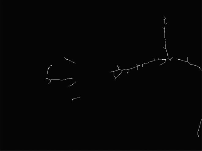
Recognition results of branch obstacle from left and right cameras. (a) Left camera; (b) right camera.
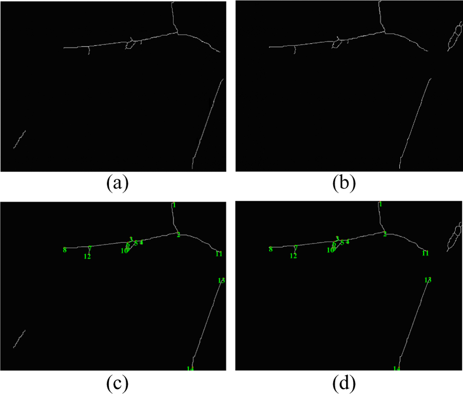
Result of stereo matching based on features. (a) The shielded skeleton recovery of left image; (b) the shielded skeleton recovery of right image; (c) left image after stereo matching; (d) right image after stereo matching.
Depth information acquisition of branch obstacle
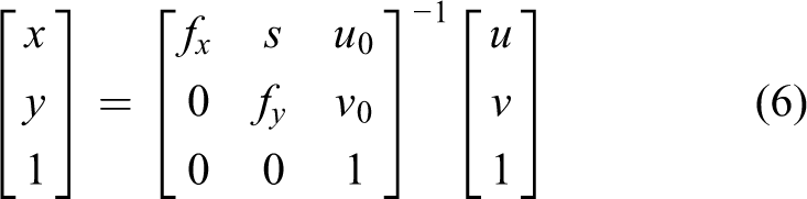
The parallax of feature points in the left and right image planes is obtained after matching (shown in Figure 12). Pl
and Pr
are the matching points in the left and right plane of feature point P. As matching feature points are in the coordinate system based on pixel, the internal parameter matrix obtained by calibration is adopted to transform the feature points in pixel coordinate system into the physical coordinates based on millimeter
19,20
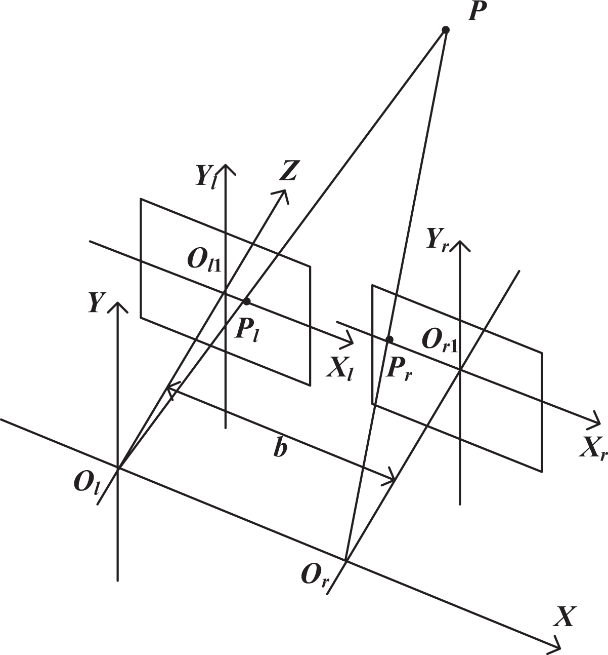
Three-dimensional information acquisition model.
After calculating, the coordinate of Pl and Pr are (xl , yl ) and (xr , yr ), the parallax d is d = xl − xr , according to the principle of limit constraint; and the same height of left and right cameras: yl = yr = y; the left camera coordinate system and the world coordinate system are set to coincide with each other for easy calculation, the coordinate values (X, Y, Z) of feature point P in the world coordinate system according to the 3D information acquisition model as shown in Figure 12 and the triangulation theory are 21
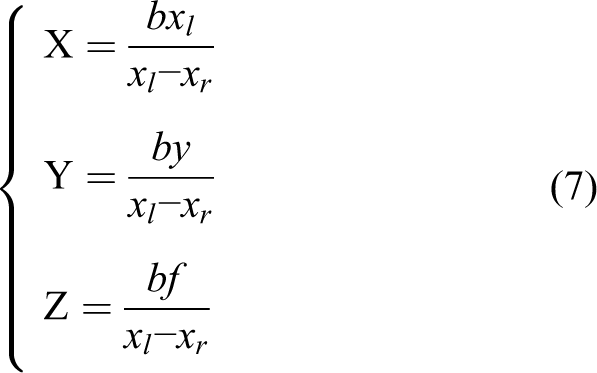
where b is the baseline distance, f is the average distance obtained by calibration between two cameras, f = 233.3 mm, Z is the distance between feature points in branch skeleton and camera. If the location is only to skeleton, which is the axis of branch, the harvesting robot will touch the branch. So the section radius must be taken into consideration, and the true deep distance Z is

where k is a safety factor. According to Ji et al., 12 k is selected as 1.05.
Experimental result and analysis
The experimental platform consists of a MV-VS220 binocular stereo vision system (Xi’An Microvision Digital Technology Co., Ltd., Xi'An,China.) and an industrial computer with Intel Core 2 Duo CPU ET3000 @ 2.66 GHz and 2 GB RAM and 320 GB hard disk. Experimental software platform is Visual C++6.0. The experiment was done in October 2015 at apple demonstration orchard of Feng Country, Jiangsu Province, China. Specific steps are as follows:
According to the picking robot workspace, the binocular stereo vision system is placed in different locations between the vision camera and the apple tree branch within the range of 500–1500 mm. When the system is in normal operation, the proposed method is used to extract all the feature points of the branch skeleton in the image of camera view and mark them with ‘+’. Then, the disparity of the feature points in the left and right image plane is obtained by stereo matching and is used to calculate the depth distance information of the feature points for the localization of branches.
In order to facilitate quantitative comparative analysis, the distances 800 mm, 1000 mm and 1200 mm, respectively, between the binocular camera and the image of apple are considered as examples to carry out the branch localization experiment. The experimental results are as follows:
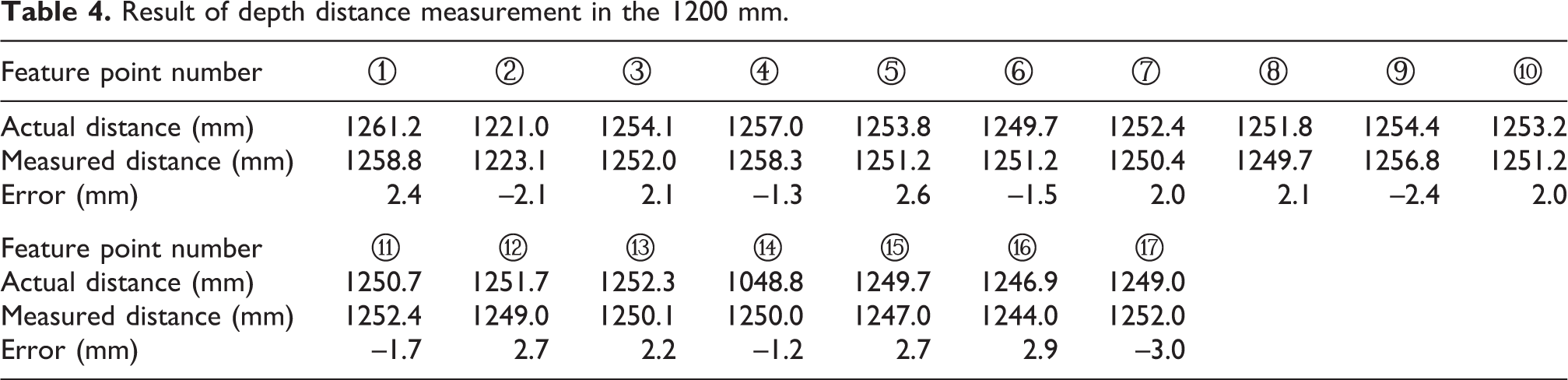
Figures 13 and 14 show the images of the left and right camera when the distance between the binocular camera and the image of the selected apple is 1000 mm; 17 and 14 same feature points of branches extracted from left and right images of Figures 13 and 14 are marked with ‘+’ and numbered one by one. Based on the proposed method, the deep distances of feature points of branches after the stereo matching and calculation are shown in Table 1 and Table 2. Here, the actual distance value is got by the manual measurement, and the measured distance value is obtained by the proposed method. Binocular stereo vision platform is moved forward and back by 200 mm, respectively, along the target direction, and repeated experiments for selection and localization of the branch feature points are carried out. Tables 3 and 4 and Tables 5 and 6 are the results when the distance between the binocular camera and the image of the selected apple is 800 mm and 1200 mm. When the distance is 800 mm, due to the shortening of distance, the view field of the camera becomes narrow. The camera only can capture the smaller part of branches. The number of extracting the feature points of branches is reduced from 17 to 10 and 14 to 8, respectively, so only the depth distance of 10 and 8 feature points are measured.

Apple tree image and feature point extraction of branch with the distance 1000 mm. (a) Apple branch left image; (b) apple branch right image.

Apple tree image and feature point extraction of branch with the distance 1000 mm. (a) Apple branch left image; (b) apple branch right image.
Result of depth distance measurement in the 1000 mm.

Result of depth distance measurement in the 1000 mm.

Result of depth distance measurement in the 800 mm.

Result of depth distance measurement in the 1200 mm.
Result of depth distance measurement in the 800 mm.

Result of depth distance measurement in the 1200 mm.

It shows that the maximal measurement error is 6.6 mm which occurred in the distance with 800 mm, whereas the minimal error is less than 1.5 mm when the distance is 1000 mm.
On the basis of the above two groups of experiments, 50 apple tree images acquired under all-weather natural conditions are used for testing. The statistical results show that the measurement error lies in [−6.2 mm, 6.6 mm]. When the distance is 800 mm and 1200 mm, the error is relatively large. However, the error is minimal within ±1.5 mm when the distance is 1000 mm.
The main causes are analysed as follows: when the distance is too small, the entire apple branch image cannot be taken from the left and right cameras at the same time and leads to the fewer feature points for matching, so the error is larger. When the distance is too big, a small error in pixel coordinate will amplify in the world coordinate system. In summary, the localization is more suitable in the distance to the object of 1000 mm in the apple harvesting robot vision localization system.
Conclusion
In this article, the vision localization method of apple branch obstacle is examined. Firstly, the branch skeleton is extracted from the morphological thinning. Secondly, the methods of removing false branch and occluded branches recovery are adopted to get the feature points of skeleton and the radius of branch is obtained by the distance transformation image. Then the stereo matching based on skeleton points is carried out, and the depth information of branch is obtained with matching parallax and triangulation theory. Finally, the obstacle branch localization experiment based on binocular vision system indicates that the error between true value and measured value of depth information lies in ±6.2 mm. Moreover, the error is merely ±1.5 mm when the distance to object is approximately 1000 mm, and the validity of proposed method has been proved.
In this article, the deep distance range with minimal error is found out by moving the camera forward and back. It provides reference information for avoiding obstacle control and path planning of harvesting robot. And the specific relationship between the target location distance and error is the key point to further improve the robot localization accuracy and time, which as well is our research emphasis on branch localization in the future.
Footnotes
Declaration of conflicting interests
The author(s) declared no potential conflicts of interest with respect to the research, authorship, and/or publication of this article.
Funding
The author(s) disclosed receipt of the following financial support for the research, authorship, and/or publication of this article: This work was supported in part by the National Natural Science Foundation of China (NSFC) Grant 31571571, the Natural Science Foundation of Jiangsu Province Grant BK20150530, the Professional Research Foundation for Advanced Talents of Jiangsu University Grant 14JDG077, and a Project Funded by the Priority Academic Program Development of JiangSu Higher Education Institutions (PAPD).