
Abstract
To replace the lost limb, the active prosthesis foot has been investigated for several decades. The current powered ankle-foot prostheses function like a human ankle using accurate control systems. However, it is still hard to accurately mimic the impedance characteristics of the human ankle, especially at the end of the controlled dorsiflexion phase. This article presents the mechanical design, optimization, and experiment evaluation of a novel powered ankle-foot prosthesis using a geared five-bar spring mechanism. Compared with the traditional structure of single axis with elastic unit, the geared five-bar spring mechanism has more flexible movements. The optimization and experiment results of the geared five-bar spring mechanism show that it can provide a better performance on impedance torque in controlled dorsiflexion phase. Compared with the traditional powered ankle-foot prosthesis, the powered ankle-foot prosthesis using the geared five-bar spring mechanism may have the ability to provide the patients with better security during controlled dorsiflexion phase.
Introduction
The human ankle-foot plays a very important role in human walking. It provides the vertical support and the propulsion of human forward progression by stretching and contraction of human muscles. 1 In the past several decades, many kinds of ankle-foot prostheses have been developed. Initially, solid-ankle cushion heel (SACH) is designed to replicate the lost normal walking function for below-knee amputees. The SACH foot is mostly made of wood and metal. Due to the strong demand of amputees to take part in the daily life, the ankle-foot prosthesis technology has been greatly developed using the energy storage and release (ESAR) technology. 2 The concept of ESAR foot is the foot, which stores energy during the mid-stance phase and releases energy during the late stance phase using carbon fiber. The echelon foot and motion foot, for example, are both ESAR foot with the adjustable hydraulic unit. Compared with the SACH foot, the ESAR foot can reduce the metabolic cost of the amputee. 3,4 Besides the ESAR foot enables higher walking velocity and larger range of motion. 5
However, based on the function of the human ankle, passive ankle-foot prostheses have more restrictions. Below-knee amputees with ESAR foot rely on the spring-back energy which is not enough to propel the human body forward at normal and fast walking speed. 6,7 Studies indicate that below-knee amputees with passive ankle-foot prostheses show asymmetry gait patterns. 8,9
Studies show that human ankle produces more energy than that it absorbs, which means that the active component is necessary for the design of ankle-foot prostheses. 10 –12 To provide additional torque and closely mimic the function of human ankle, powered ankle-foot prostheses, which are based on the biomechanics and energetics of human ankle, are designed and studied. Many theoretical model have been investigated to be applied to the powered ankle-foot prosthesis. 13 –15
The primary challenges in the development of powered ankle-foot prostheses include the demand of considerable power and precise control of the impedance torque. 16 To decrease the power demand of the active ankle-foot prosthesis, in recent studies, Hitt et a. 17 presents the design methodology and model verification of a robotic transtibial prosthesis is named SPARKY. The biomechanical energy regeneration technology is applied to reduce the energy consumption by the combination of a spring and a robotic tendon actuator. Herr 18 presents commercially available powered ankle-foot prosthesis. It comprises a 200-W DC brushless motor and ball-screw transmission in series with a carbon-composite leaf spring. This foot provides a net-positive power assist during the stance period of walking. It can closely mimic the function of the human ankle. Safaeepour et al. 19 propose a novel viscoelastic ankle-foot prosthesis. The prosthesis contains two pneumatic cylinders: one works during the early stance phase and the swing (SW) phase and another saves the energy during the mid-stance phase and supplements the energy during the late stance phase. Cherelle et al. 20 present an energy-efficient, powered transtibial prosthesis called AMP-Foot 2.0. The prosthesis stores energy in springs during the complete stance phase that can be released at push off. Due to this, it can provide the full power necessary for forward propulsion with a low power actuator. Bergelin 21 presents an active prosthesis using a four-bar mechanism. The simulation results prove that it can provide a range of motion similar to that of the normal human ankle.
To closely realize the characteristics of the impedance torque of the human ankle, current researchers usually use various control systems. 22 –26 Studies 27 –30 show that inefficient impedance torque of the human ankle will lead to the differences in the value of dorsiflexion and plantarflexion. At the end of the controlled dorsiflexion (CD) phase, the slope of the torque versus angle curve of the human ankle becomes infinity to protect the human ankle from excessive flexion. Although the current powered ankle-foot prostheses can closely behave the function of human ankle using accurate control systems, they are hard to accurately and stably mimic the impedance characteristics of the human ankle, especially at the end of the CD phase. By contrast, some passive prosthesis can provide stable and reliable support in CD phase without the control system.
Therefore, in this article, we propose an active ankle-foot prosthesis, which can passively provide amputees with accurate impedance torque in CD phase using the geared five-bar spring (GFBS) mechanism. 31,32 At the same time, the GFBS mechanism can reduce the power demand by storing energy during the CD phase and release the energy in the powered plantarflexion (PP) phase. It may provide better stability in the CD phase.
It should be noted that the design and control strategy for different types of prostheses, for example, transtibial prosthesis and transfemoral prosthesis, are different. But the type of the amputation doesn’t affect the demand of the torque and angle of the ankle prosthesis. It will affect the gait and posture of amputees with different amputation. The transfemoral prosthesis 33 needs both a powered ankle joint and a powered knee joint to attain a better performance. In this article, our prosthesis is applied to transtibial amputees.
Biomechanics and model type selection
Human walking biomechanics
It is important to consider the human biomechanics for the design and development of the powered ankle-foot prosthesis. The angle, torque, and trajectory of the ankle are collected for the quantization of the human biomechanics during different walking conditions. Although the walking data change across different walking conditions, the characteristics of the human biomechanics remain similar. 16,27 The ankle torque versus ankle angle curve is widely analyzed in research to mimic the function of the human ankle. This curve displays narrow hysteresis loop at normal walking speed (0.5–1.75 m/s). A complete gait cycle begins when one foot touches the ground and ends at the next heel strike of the same foot. Usually, the intact gait cycle contains two main subdivisions: the stance phase (62%) and the SW phase (38%). The stance phase contains controlled plantarflexion (CP), CD, and PP.
A typical intact ankle torque–angle curve or a 75-kg person at 1.25 m/s is shown in Figure 1 (data obtained from Au et al. 34 ), which can be divided into four distinct phases as follows:

A typical intact ankle torque versus angle curve.
CP phase: As shown in Figure 1(1) and (2), CP starts at the heel strike and ends at the foot flat. The human ankle absorbs the impact force 35 and controls the rate of forefoot slap. During CP, the human ankle behavior is similar to a linear spring.
CD phase: As shown in Figure 1(2) and (3), CD starts at the foot flat and keeps going till the ankle reaches a state of maximum dorsiflexion. During CD, the ankle stores energy and provides the vertical support. The ankle power is predominately negative, and the ankle behavior can be characterized by a nonlinear spring 6. As shown in Figure 1, the ankle stiffness increases with the increase in the ankle angle. Passive elements are usually considered to model the ankle during CD. The optimized GFBS mechanism should have similar stiffness characteristics with the human ankle to efficiently mimic the function of human ankle during CD.
PP phase: As shown in Figure 1(3) and (4), PP starts at the ankle reaching a state of maximum dorsiflexion and ends at the toe off. During PP, the ankle releases the stored energy and provides additional energy for the forward propulsion. The prosthesis with the GFBS mechanism should release energy stored in spring and provide additional power for the forward propulsion by a torque actuator.
SW phase: As shown in Figure 1(4) and (1), SW starts at the toe off and ends at the heel strike of the same foot. During SW, the human ankle adjusts the ankle angle to equilibrium position, which can avoid the friction between the toe and ground.
Model type selection
It is generally believed that the performance of the human ankle is similar to a single axis hinge (shown in Figure 2a). Hence, the series ankle elasticity 17,36 (SAE) model is widely used in the design of the prosthesis foot. The architecture of the traditional SAE mechanism is demonstrated in Figure 2(b). The simplified SAE mechanism consists of two bars and an elastic unit (spring or cylinder). Hinge A represents the human ankle joint, while linkages AB and AC represent the human foot and shank, respectively. In a closed-chain multibar mechanism, a pair of hinges that are not adjacent is called the opposite hinges. As can be seen in Figure 2(b), the traditional SAE model can be considered as a four-bar mechanism with a spring hinged between the opposite hinges.
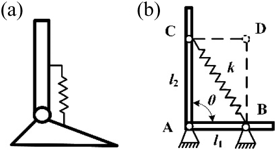
A typical intact ankle torque versus angle curve. (a) The human ankle model. (b) The traditional SAE mechanism model. SAE: series ankle elasticity.
The traditional 2-degree of freedom (DOF) closed-chain five-bar linkage mechanism is illustrated in Figure 3(a), which consists of five linkages sequentially linked by five hinges. When a pair of gears is added to a pair of adjacent hinges, it becomes the 1-DOF geared five-bar (GFB) mechanism. In Figure 3(b), the two gears are fixed on AE and BC. It means that the gears have the same rotation with the linkages where they are fixed. Hence, the GFB mechanism is supposed to consist of three linkages with no gear (AB, CD, and DE), two linkages with one gear (BC and EA), one linkage with two gear (AB), and five hinges (A, B, C, D, and E).

(a) The traditional five-bar linkages mechanism. (b) Type A: the GFB mechanism with the reversed direction of rotation. (c) Type B: the GFB mechanism with the same direction of rotation. GFB: geared five-bar.
As mentioned above, the traditional closed-chain five-bar linkage mechanism has two DOF, while the GFB mechanism has one DOF, as a result of which only one input is required to be specified for the GFB mechanism. For type A (Figure 3b), the input is set for geared linkage AE named drive component. And BC rotates in the opposite direction of AE. In the type B (Figure 3c), BC rotates in the same direction as AE. There are two gears in type A and three gears in type B.
One primary issue of the GFBS mechanism, to be applied to ankle joint model, is the choice of the hinges to be used as the ankle joint. Generally, the DC motor is supposed to be fixed on the shank so as to reduce the volume of the ankle-foot prosthesis, and the input should be set for a joint or a geared linkage. Therefore, hinges A and B can be selected as ankle joints with regard to the mechanical stability. A is symmetric to B on a dash line (Figure 3b). Hence, we choose hinge A as the ankle joint. There are two linkages connected to hinge A: AB (a linkage with two gears) and AE (a linkage with one gear). In order to avoid the interference of the DC motor and the gear, AE is selected as the shank and AB as the foot.
Another essential concern of the GFBS mechanism being used as ankle joint model is the location where the spring should be placed at. To simplify the optimization, the location of the spring is limited to the hinge axes. There are five hinges in the GFB mechanism (Figure 3b), where hinge A is connected to the transmission unit of the DC motor. Nevertheless, to avoid the interference of the spring and the transmission unit, hinge A cannot be connected to the spring. Hence, there are three pairs of the opposite hinges: B and D; B and E; and C and E. However, when A is chosen as the ankle joint and BE as the spring position, the triangle ABE with the spring is the same as the traditional SAE mechanism. Hence, two options are available for the position of the spring: B and D named position 1 (P1), C and E named position 2 (P2). Regarding the direction of rotation (type A and type B), there are four possible configurations of the GFBS model as shown in Figure 4, which are numbered with types 1, 2, 3, and 4. Types 1 and 2 are applied with the type A GFB mechanism, while types 3 and 4 implement the type B GFB mechanism.

Four possible configurations of the GFBS ankle-foot models. (a) Type 1: combination of P1 and type A. (b) Type 2: combination of P2 and type A. (c) Type 3: combination of P1 and type B. (d) Type 4: combination of P2 and type B. GFBS: geared five-bar spring.
According to the impedance characteristics of the ankle during CD, the stiffness of the GFBS model applied to the ankle-foot prosthesis mechanical model should increase with increasing ankle angle. Four potential GFBS ankle-foot models are tested for the selection, the initially optimized test parameters are listed in Table 1.
Test parameters.

The impedance torque versus rotation angle curves of the four types of the GFBS models are depicted in Figure 5. The typical intact ankle torque versus angle curve during CD is also plotted in Figure 5. The rotation range of the human ankle during CD is nearly 20°. In the selection of the optimal GFBS model, the x-axis is set from 0° to 30°. In addition, the four types of the GFBS models have the same direction of rotation with the human ankle during CD.

The impedance torque versus rotation angle curves of the four types of the GFBS models and the human ankle during CD. GFBS: geared five-bar spring; CD: controlled dorsiflexion.
By comparing the characteristics of the slope and the value of curves in Figure 5, it can be found that type 1 is the one whose curve best fit the curve of the human ankle during CD. Compared to the concave torque–angle curve of the human ankle, types 2 and 4 have different curvature. Therefore, type 1 is chosen to be the model for imitating the human ankle.
Optimization of the GFBS mechanism model
The optimized synthesis of the GFBS mechanism is of great importance for the prosthesis to precisely imitate the human impedance. As depicted in Figure 6, nine parameters for GFBS mechanism need to be optimized: the length of five linkages (l1, l2, l3, l4, and l5), the gear ratio r (g1–g3), the initial angular positions θ 1 and θ 3, and the spring stiffness k. Parameters α 1 and α 3 refer to the rotated angle of AE and BC, respectively.

The position of the GFBS mechanism. GFBS: geared five-bar spring.
In order to obtain the impedance torque of the GFBS mechanism, first the positional kinematics of the GFB mechanism should be calculated.
In Figure 6, a GFBS mechanism is presented schematically. The solid line shows the coordinate diagram of the GFBS mechanism. The dash line shows the coordinate diagram of the GFBS mechanism after AE rotating angle α 1. AB is fixed on the x-axis. According to the geometry of the GFB mechanism, the following formulations can be derived:


The original length of the spring l 0 can be determined by:

Equations for the two gears are:

The rotated angle of BC is derived by:

When AE rotates α
1, the GFB mechanism in new position (the dash line in Figure 6) should be solved again. The orientations

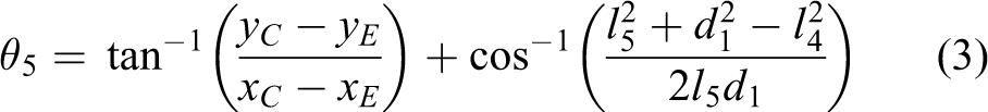
Through Equations (1), (2), and (9), the coordinate values of points E′ and C′ can be determined, respectively. Once the coordinate values of points E′ and C′ are known, the coordinate values of point D′ can be calculated by:

Then, the GFB mechanism after AE rotating α 1 degree can be solved. The free length l of the spring can be obtained by:

The spring force FS is given as:

During CD, the GFBS mechanism keeps the ankle joint balanced. The force condition of the GFBS mechanism during CD is shown in Figure 7.

The force condition of the GFBS mechanism. GFBS: geared five-bar spring.
By analyzing the force condition of point D′, the following equations can be derived:


When


The torque of gear 1 to gear 3 and gear 3 to gear 1 are named M13 and M31, respectively. The impedance torque of the GFBS mechanism is named M1. By using Equation (7), the following can be obtained:

The impedance torque of the GFBS mechanism can be derived from Equations (15) to (17). Then, once the rotated angle α is known, the impedance torque M1 of the GFBS mechanism can be given as:

The solving process of the impedance torque of the GFBS mechanism is shown in the flowchart (Figure 8).

The flowchart of the GFBS-solving process. GFBS: geared five-bar spring.
Fifty points are selected in the typical intact ankle torque versus angle curve during CD, with the data from Equation (19). Each point has an angle value

In order to evaluate the quality of parameters, the least squares method is applied to the optimization of the GFBS mechanism. The optimization objective function is:

For a normal male adult, the foot breadth is almost 100 mm, the foot length is almost 260 mm, and the length from the ankle joint to tiptoe is almost 150 mm. Considering the size and the intensity of the hinges, it is defined that the length of all linkages in the GFBS mechanism ranges from 20 to 80 mm. With regard to the range of the ankle rotation, the initial angular positions θ1 and θ3 are supposed to range from 0.15 to 2 rad. And considering the mechanical structure and assembly of the GFBS mechanism, the gear ratio is expected to range from 1/4 to 4 and the spring stiffness should be no more than 40 kN/m. Hence, the constraints are expressed as follows:


The fmincon function in the MATLAB optimization toolbox is applied to this article. In order to achieve optimal results, the traversal method is applied to find the initial point, which can be obtained by increasing or decreasing parameters in the specified range. The valid initial point and the optimization results (final point of the fmincon function) of the GFBS mechanism are shown in Table 2.
Optimization parameters of GFBS.
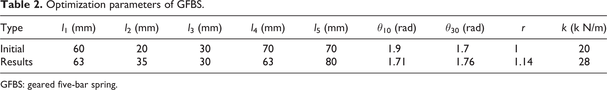
GFBS: geared five-bar spring.
Mechanical design and function control
A SolidWorks model of the prototype is shown in Figure 9. The prototype is mostly made of aluminum (6061). As shown in Figure 9, the GFBS ankle-foot prosthesis consists of four main elements: a DC motor (Maxon RE35, 90W ), a transmission unit, a GFBS mechanism, and a foot plate. Since the motor is cylindrical, the DC motor is placed in the shank plate. The transmission unit consists of a gearbox (200:1) and a pair of bevel gears (2:1). The energy of the DC motor can be transmitted to the axis of the ankle joint through the gearbox and the pair of bevel gear. The traditional joint structure is replaced by the GFBS mechanism, which is in parallel with the ankle joint. When the human shank rotates forward around the ankle joint during CD, the spring of the GFBS mechanism is compressed. In this way, the prosthesis stores energy and provides the vertical support for the forward rotation of the shank during CD.

The SolidWorks model of the prototype.
The GFBS prosthesis foot is designed to have a 70 mm height of ankle joint, 90 mm width of breadth, and 260 mm width of anterior posterior. The initial ankle angle of the GFBS prosthesis foot is set at 96°, while the rotation range of the GFBS mechanism is set at −35° to 20°.
Two pressure sensors (500 Hz) are applied in the GFBS prosthesis foot to detect the current gait phase and two gyro sensors (MPU 6050, 300 kHz) to determine the current ankle angle. In Figure 9, it is shown that the two pressure sensors are placed on the forefoot plate and the heel plate, respectively. An Arduino (Mega2560) is used to record the value of sensors. Since the human gait is a periodic motion, the finite-state control method 37 –40 has been widely used in the control of powered ankle-foot prosthesis. The detection of the heel strike and the forefoot strike is performed by analyzing the values of the two pressure sensors.
During CP, the prosthesis is controlled to rotate till the foot flat. The angle of this prosthesis joint should follow the rotation of the normal ankle. When the pressure sensors detect the heel strike, the Arduino microcontroller will give specific voltage to the controller of the Maxon motor. Then the operation of this Maxon motor is controlled by position control strategy during CP.
During CD, the GFBS mechanism works independently to provide the impedance torque for the ankle joint. During CD, the motor follows the rotation of the ankle angle but doesn’t provide any additional torque to the joint. Due to the features of our GFBS mechanism, if the control system breaks down, the prosthesis can still work passively and precisely during CD phase.
During PP, the GFBS mechanism and the DC motor provide the impedance torque simultaneously. Once the current ankle angle is known, the motor moment MM can be determined by the following equation:

During SW, the GFBS prosthesis foot works as a position control system. The DC motor adjusts the ankle angle to prepare for the next heel strike of the same foot. The control flowchart is shown in Figure 10.
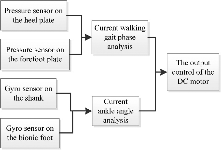
The control flowchart of the GFBS prosthesis foot. GFBS: geared five-bar spring.
Simulation, experiment, and discussion
Simulation using Adams
In order to verify the accuracy of the calculation, we conduct a simulation experiment using Adams [X64 2013] software. As shown in Figure 11, the model of Adams is established based on the SolidWorks model. The length of every bar and the spring stiffness are set using the optimization results. The blue part is the foot plate, which is fixed on the ground in this simulation. The green part and red part are a pair of gears. The gear ratio is set according to the optimization results. And we also set a motion that can make the leg rotate forward the ankle joint. Then the torque value of the ankle joint is recorded during CD in this simulation.
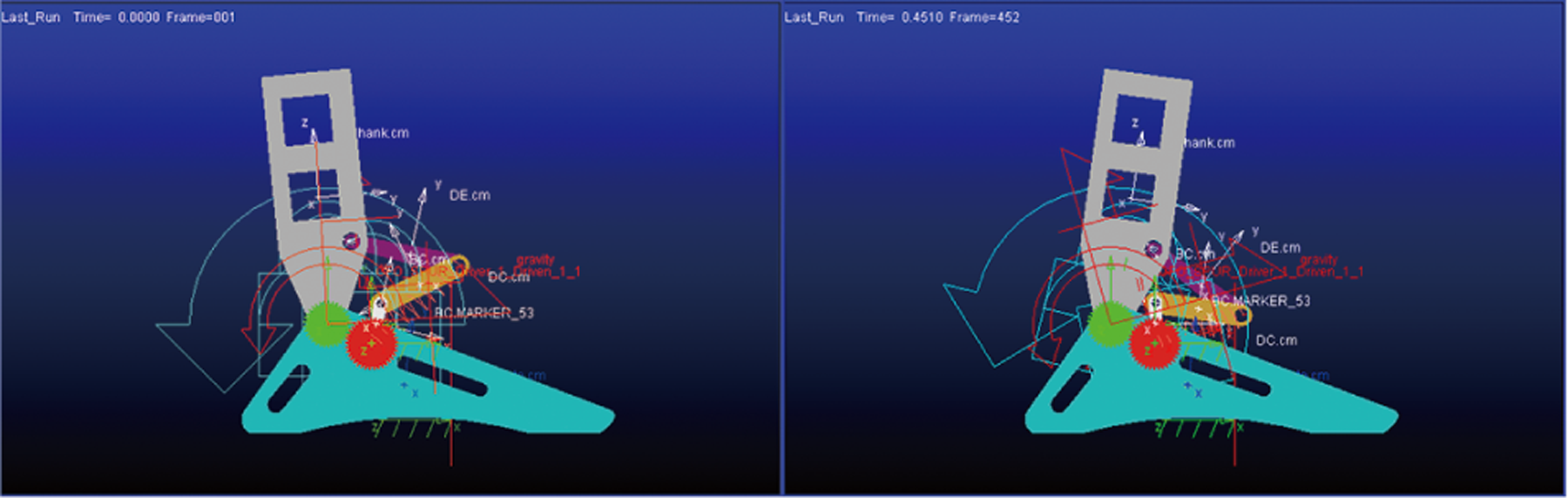
The Adams simulation experiment.
The simulation result is depicted in Figure 12. It can be seen that the GFBS mechanism can reach peak torque of 120 Nm. And the slope of the torque curve increases with increasing time.
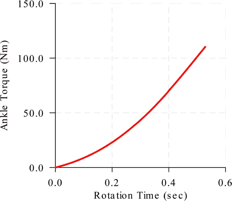
The results of Adams simulation.
Static mechanical experiment
A static mechanical experiment is conducted to verify the impedance characteristics of the GFBS mechanism during CD as shown in Figure 13. Different masses are added to simulate the variation in the external torque. Moreover, the angle of the ankle joint rotation is recorded.
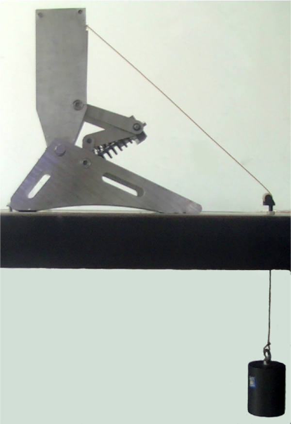
The impedance test of the GFBS prosthesis foot. GFBS: geared five-bar spring.
The result of the static mechanical experiment is shown in Figure 14. It can be found that the prototype has a larger impedance torque until overtaken by optimization results at 7°. This is due to friction at hinges between different bars and gears. However, there is no big deviation among the results of the Adams simulation, the optimization, and the static mechanical experiment. Therefore, the above calculation process is correct.
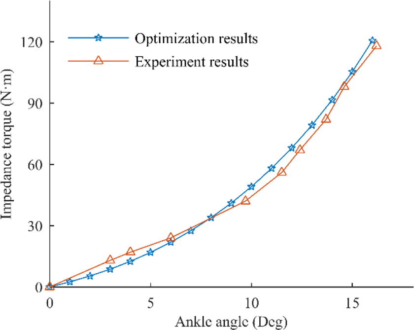
The comparison of the optimization result and the experiment result of the GFBS mechanism. GFBS: geared five-bar spring.
Application experiment
In order to evaluate the dynamic performance of the powered GFBS ankle-foot prosthesis, the prototype is tested for a volunteer (male, 180 cm, 75 kg, 1.2 m/s and level-ground) wearing an amputee simulator (Figure 15). LED lights are used as markers. And the gait data are captured by a high-speed camera (JVC GC-PX100BAC, 250 fps). By spotting the position of the LED lights in the picture, the current angle of the ankle joint rotation can be obtained. Meanwhile, an experiment without prosthesis is conducted to collect the trajectory of the ankle joint with the same volunteer in normal walking condition (1.2 m/s and level ground).

Test the prosthesis in a volunteer wearing an amputee simulator.
The experiment results are depicted in Figures 16 and 17. It can be found that the GFBS prosthesis foot can give volunteer ability to work naturally. Especially, the GFBS prosthesis can provide good performance during CD. The deviation in CD is the smallest among the four gait phases. However, compared with the normal ankle, there is a delay in the ankle dorsiflexion versus gait curve of the prototype. This is because the basic proportion integration differentiation (PID) control values should be modified based on different human subjects. The value of dorsiflexion angle at foot flat is larger than that of the normal ankle. This may be because there is no angle constrains in our control strategy. So the foot will clap on the ground.

The ankle dorsiflexion versus gait curve.

The ankle torque versus gait curve.
After several tests, the volunteer reported that the prosthesis can provide stable and comfortable support during CD, but the active force was obviously inefficient in PP. As can be seen in Figure 17, there is an obvious derivation between the normal ankle and the prototype in PP phase. It means the additional torque in PP phase is not enough. And this may explain why there is a big deviation in the ankle dorsiflexion between our prototype and the normal ankle.
Discussion: Comparison of our GFBS and SAE
To compare the impedance characteristics of the GFBS mechanism and the traditional SAE mechanism, the same method is used to calculate the impedance torque of the optimized SAE. As seen in Figure 2(b), four parameters need to be considered: the length of two linkages (l1, l2), the initial angular position θ, and the spring stiffness k. The least square method is also applied to the optimization of the SAE. The constraints are determined by the size of the structure and the design of the spring as:

The initial point and the optimization results are shown in Table 3.
Optimization parameters of SAE.

SAE: series ankle elasticity.
The impedance toque versus ankle angle curves (T–A curves) of the optimized GFBS and SAE mechanism are shown in Figure 18, where the human ankle has a nonlinear impedance torque versus ankle angle curve during CD. In this figure, the ankle angle is defined as the angle that ankle joint rotated from the beginning of CD. It can be found that the impedance torque values of the GFBS and SAE mechanism increase with increasing angle of ankle, which is similar to the normal ankle. The SAE mechanism has the largest torque value until overtaken by the GFBS mechanism at 12.4° and the normal ankle at 13.7°.
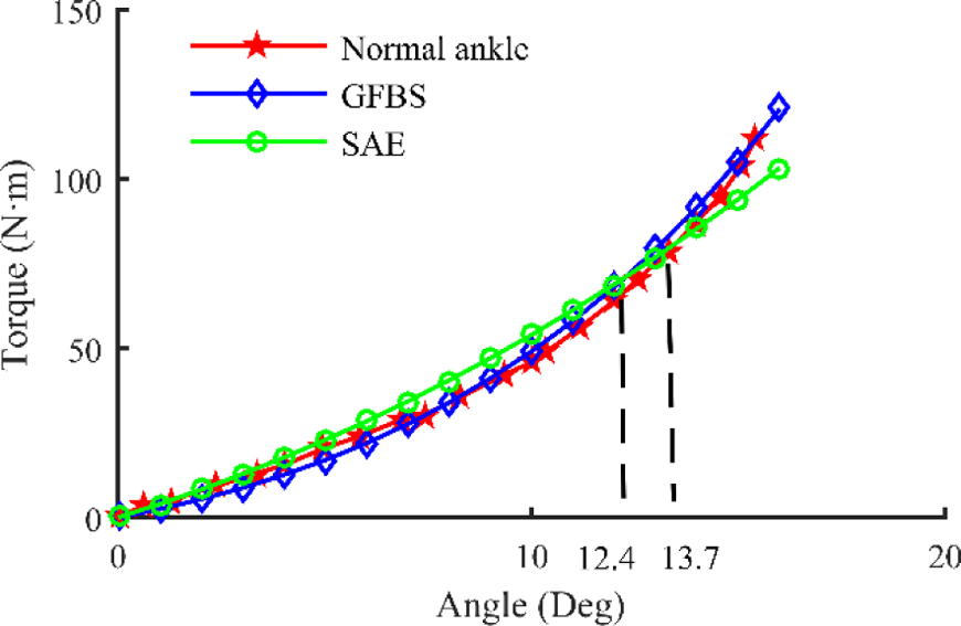
The impedance torque versus ankle angle curves of the GFBS and SAE mechanism during CD. GFBS: geared five-bar spring; SAE: series ankle elasticity; CD: controlled dorsiflexion.
For a more detailed assessment, an evaluation index called the root mean square error (RMSE) is introduced to this article. The RMSE can be obtained by the following equation:

where Xobs
is torque value of GFBS or SAE,
Xmodel
is torque value of the normal ankle, and
n is the number of points for calculation.
The RMSE is shown in Table 4. It can be found that the RMSE of the GFBS is 66.46% of the SAE on the torque values. Therefore, the GFBS mechanism is closer to the normal ankle than the SAE mechanism on the value of impedance torque.
The root mean square error.

GFBS: geared five-bar spring; SAE: series ankle elasticity.
The slope of the impedance torque versus ankle angle curves is depicted in Figure 19. There is a big deviation between the SAE mechanism and the normal ankle, especially after 9°. By contrast, the slope of the GFBS mechanism is very close to that of the normal ankle. The RMSE of the slope of the GFBS is just 37% of that of the SAE mechanism. It can be seen that, the T–A curves of the GFBS mechanism and the normal ankle have the same slope after 12.5°. Therefore, the GFBS mechanism can provide better security at the ending of CD.

The slope of the impedance torque versus ankle angle curves.
Conclusions
According to the impedance characteristics of the human ankle, the GFBS mechanism is applied to realize the structure and function of the human ankle with one DOF.
The design parameters of the GFBS mechanism is optimized for achieving precise impedance torque in CD. The results of the optimization show that the GFBS mechanism can closely mimic the impedance characteristics of the human ankle during CD. The Adams simulation and the static mechanical experiment verify that the calculation process is correct.
Compared with the SAE mechanism, the GFBS mechanism provides prosthesis with better impedance characteristics on values of the impedance torque and the slope of the impedance torque versus angle curves. At the end of CD, the GFBS has the same slope with the human ankle, which enables amputee to have the limitation of an excessive flexion. Hence, the GFBS prosthesis foot can provide amputee with better support and security during CD.
The results of the nonamputee experiment show that the GFBS prosthesis foot can provide volunteer with close function of the human ankle but the active force during PP is obviously inefficient, which means we need to improve the performance of the power transmission system in the next generation.
In our further study, we will focus on improving the performance of our prosthesis at different speed and different terrains. At the same time, we need to improve our control strategy to avoid clapping on the ground during the CP phase.
Footnotes
Declaration of conflicting interests
The author(s) declared no potential conflicts of interest with respect to the research, authorship, and/or publication of this article.
Funding
The author(s) disclosed receipt of the following financial support for the research, authorship, and/or publication of this article: This work is supported by the National Natural Science Foundation of China (50975230) and Research fund for the Doctoral Program of Higher Education of China (20136102130001).