
Abstract
This article presents a novel sensorless control system of assistive robotic ankle-foot prosthesis, two estimation algorithms were developed and an analogy between them has been made. The system actuator’s motor is a permanent magnet synchronous motor, unlike other powered ankle-foot, where the brushless DC motor and DC motor were used. Utilizing the permanent magnet synchronous motor will reduce the torque ripples and increase system ability to be overloaded compared to systems which utilize the brushless DC motor. Moreover, the ability of the machine to operate in all speed range makes this machine more suitable for the application. Both estimation algorithms are built using C-code and assessed in MATLAB Simulink. The estimation algorithms are used to provide motor and powered ankle-foot’s angular speed and position. Two-level control system is used to evaluate the estimation algorithms; the control system role is to mimic biological ankle-foot performance during normal ground level walking speed. Based on the result of this article the unscented Kalman filter (UKF) is applicable for the application, as a result of the observer ability to estimate the motor load and angular position. On the other hand, extended Kalman filter (EKF) accuracy is affected by the load applied to the motor. Furthermore, the angular position is evaluated by integration of the angular speed which means integration of angular speed estimation error.
Keywords
Introduction
It is believed that ankle plantar flexion (PF) has an important role during the gait cycle. 1 Ankle PF muscles are responsible for generating approximately 80% of the torque required by the gait cycle, which has an important distribution to regulate the whole-body angular momentum (H). 2 As a result, transtibial amputees suffer from higher falling risk compared to non-amputees and the risk vary in different walking speed and/or terrains. 2,3 The use of passive prosthetic foot is the cause of many short-term gait problems (asymmetric gait, higher metabolic consumption, and so on.) and long-term health problems (osteoarthritis, backache, and so on.). 4
Recently, the robotic lower limb prosthesis has been developed to restore ankle PF roles, in 2007 MIT’s powered ankle-foot was the first prototype able to generate enough torque for normal speed walking. 5 Then in the MIT Media Lab Biomechatronics Research group proved that the powered ankle-foot prototype could enhance metabolic economy from 6 to 20% compared to passive elastic prostheses. 6 The spring ankle with regenerative kinetics (SPARKy) project introduced a mechanical design and control algorithm for a powered ankle-foot, and the main objective of the project was designing powered prosthesis to work efficiently in different speed operation. 7,8 In 2008, SPARKy project developed the mechanical design of powered ankle-foot and introduce SPARKy version two and three. 9 Nonetheless, there are no published data about the performances of the new designs. Furthermore, a two-degree of freedom (DoF) powered prosthetic ankle-foot with a toe joint was developed, 10 followed by the design control algorithm of Zhu et al. 11 Nevertheless, there was no notable enhancement compared to single DoF powered ankle-foot. A light weight robotic ankle-foot with a novel damping controller developed by Wang et al., 12 the design and control system were amended to reach the final prototype in 2015. 13 However, the damping controller has a slow response, so the problem of asymmetric gait cycle was not solved. Another prototype was developed by Shultz et al., 14 researchers introduced a mechanical system prototype with ground level walking control algorithm, then design was enhanced by replacing the 4-pole brushless DC (BLDC) motor with 14-pole one to reduce motor torque ripples and introducing a fifth-order impedance controller. 15 The new controller used with new high level controller to master walking in different speed and standing adaptively according to ground slopes, finally walking on uneven terrain as shown by Shultz et al. 16,17 A more descriptive reviews on robotic prostheses’ control algorithms and mechanical prototypes given in the literatures. 18 –20
All powered ankle-foot control system used encoders to acquire the angular position and speed of the motor and ankle end effector (in some cases two encoders were used in MIT ankle-foot), which would make the suggested algorithm applicable to implement in any system. Furthermore, almost all portable robotic prostheses researchers utilized BLDC or DC motor 18 in system actuators; in this article, the permanent magnet synchronous motor (PMSM also known as BLDC with sinusoidal commutation) is used as system’s electrical machine. A comparison between the electrical machines can be summarized as shown in Table 1. The main drawback of PMSM compared to BLDC is the ratio between the generated torque and weight (10% less). However, the overall increase in motor weight is 30 g, which does not affect the applicability of the motor in the powered ankle-foot system.
A comparison between three electrical machines applicable to the application.

BLDC motor: brushless DC motor; PMSM: permanent magnet synchronous motor.
Estimation algorithms
The sensorless drivers depend on estimation algorithms to complete the feedback control-loop instead of utilizing position encoder to measure system angular position. Basically, estimation algorithms could be divided into: Fundamental excitation, saliency and signal injection, and artificial intelligence (AI)-based observers. 21
The sensorless driving techniques have many advantages, which can be classified into mechanical and electronic. Using sensorless control systems reduce the actuators’ design complexity and cost, increase actuators sturdiness and reliability, and enhance actuators’ noise immunity. 22 Moreover, the estimation algorithms in sensorless drivers can be implemented with any control technique (force oriented control or direct torque control). Table 2 illustrates the pros and cons of the well-known estimation techniques.
A compression between common estimation algorithms.

KF: Kalman filter; AI: artificial intelligence.
In this article, two model-based algorithms are used to estimate the PMSM angular speed and position. The model-based methods are used to be a trade-off between computation cost and accuracy. The PMSM dynamic model in the quadratic rotation frame (dq reference frame) was used in both algorithms. For more description on machine mathematical model and common control algorithms, readers can refer the works of Vas 22 and Chiasson. 23
Extended Kalman filter
The extended Kalman filter (EKF) became a basic technique, which is used in nonlinear estimation and machine learning applications. The main procedure for EKF is propagation of Gaussian random variable (GRV) in a system’s dynamic model. More precisely, the state distribution is approximately represented as GRV, and then it propagates through the first-order linearization of the nonlinear system. The estimated state variables of EKF (
Prediction stage
In this stage, a computation of two components is performed. Firstly, the predicted state variables


Kalman gain
A computation of Kalman gain (

Correction and update stage
The predicted values are in a correction stage to compute the corrected state variables and covariance matrix for next sample time as shown in equations (8) and (9), respectively, where


Unscented Kalman filter
For highly nonlinear process, depending on the first-order linearization is inaccurate and leads to a high estimation error. Julier and Uhlmann 24 introduced the unscented transformation to approximate the probability distribution based on a set of sampled points by so-called “sigma-points,” which propagate through the nonlinear model of the system. Consequently, the estimation accuracy of mean and covariance increases. The overall accuracy could be as accurate as using the third-order (in some cases it may reach the fifth-order) linearization. Almost the same procedure of EKF is followed in Unscented Kalman filter (UKF), the differences are finding sigma-points and there is no need to find the linearized model from the dynamic model of the system. For more detail about UKF, readers can refer to the study by Wan and Van Der Merwe. 25
Prediction stage
The initial step of the algorithm is the computation of a scale parameter λ based on three constant parameters (α, β, and κ). Then, four weight parameters are calculated as illustrated in equations (13) to (15). The weight parameters along with estimated state variables are used in sigma-points determination, and estimated state variables (


Compute sigma-points
Cholesky decomposition is applied to compute (c


Predict state variables and covariance matrix
Based on weight average technique, predicted state variables (


Kalman gain
To calculate Kalman gain, the output covariance and the cross-covariance between state variables and outputs (


Correction and update stage
As in EKF, the predicted state variables and covariance are corrected using Kalman gain, then update all algorithm matrices and vectors for the next sample time, where


Control algorithm
The two-level control system was chosen with the aim of testing estimation algorithms accuracy. A series elastic actuator based on PMSM is driving the robotic ankle-foot end effector. Figure 1 illustrates the powered ankle-foot schematic model. Furthermore, in ground level walking, the role of damper can be neglected as a result of low angular speed during dorsiflexion (DF).

Schematic model of powered ankle-foot with parallel damper.
High level control system
The high level is a FSM 6,14 to distinguish five gait’s subsections (PF, DF, power planer flexion (PP), and two subsections in swing phase) as illustrated in Figure 2. The biological ankle-foot trajectory given is the average of five gait cycles of 70 kg normal subject captured using Vicon system (Oxford, UK) in the motion laboratory.

Normal subject ankle-foot trajectory for one gait cycle divided into five subsections should be differentiated by the control system.
Moreover, the second duty of high-level controller is to regulate powered ankle-foot stiffness, while impedance controller is the dominant controller. Therefore, the controller is providing four different stiffness to the powered ankle-foot to mimic normal ankle-foot behavior.
Low level control system
The prosthesis’ end effector has a bond contact with working terrains, so, when it is not possible to model working environment depending on position controller, it is not suitable for application. Therefore, a simple impedance controller has chosen equations (33) to (36) to represent the controllers of four subsections (τa,xx is the required ankle torque during the subphase xx, Kxx
and Bxx
is respectively the required stiffness and damping during subphase xx, Δτ
PP is the offset torque during the PP, and


The overall control system can be represented in a block diagram as shown in Figure 3. It is important to note that the decoupling block has an important role, because motor’s shaft has angular speed during operation and the controller is not a position controller, where the angular speed is equal to zero in steady state. Motor current controllers are designed based on zero-pole cancelation, in contrast to other controllers’ parameters, which were tuned based on trial and error to get sufficient performance of the robotic ankle-foot prosthesis. Moreover, the torque command is transferred to current command, and this is one advantage of using PMSM where the relationship between the generated torque and the quadratic rotating frame Isq is totally linear.
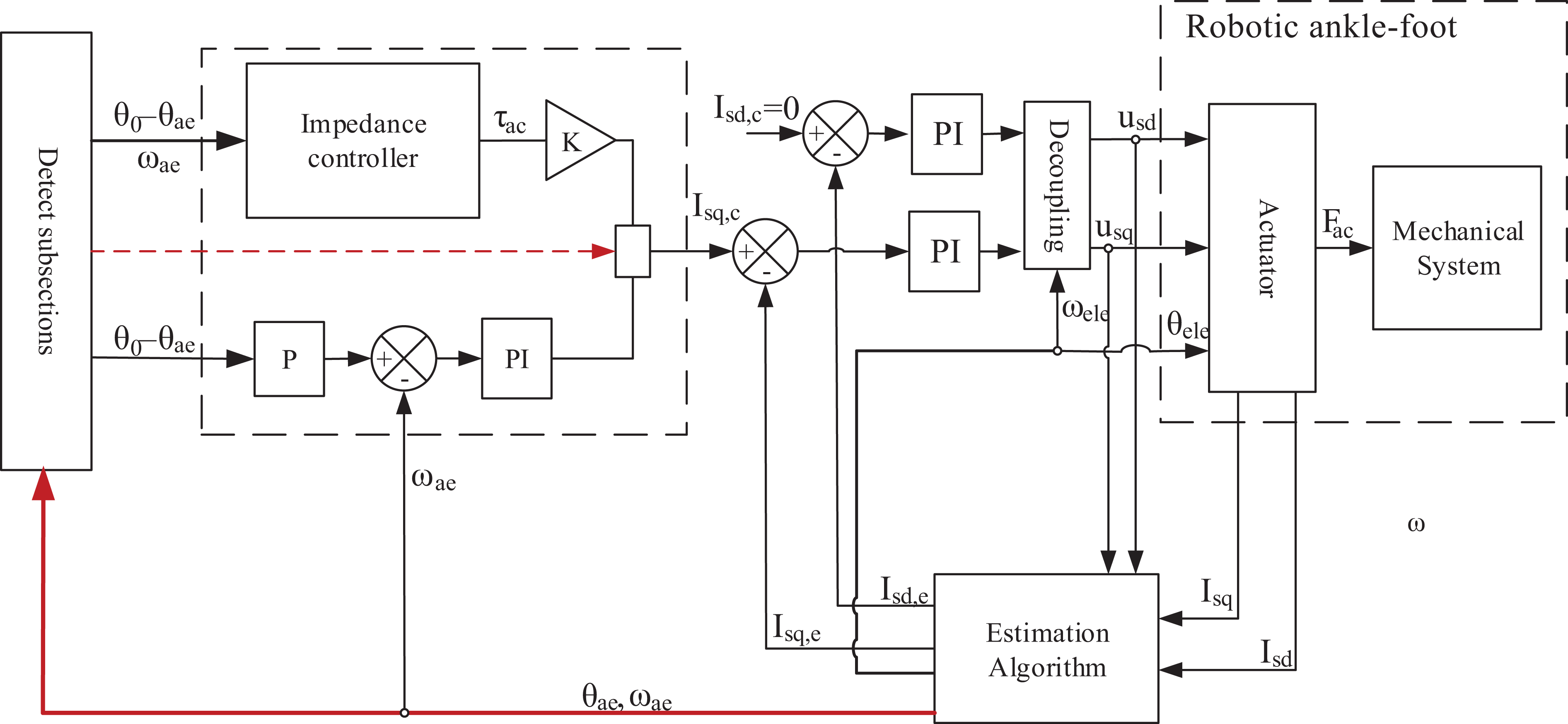
Sensorless control system for robotic ankle-foot.
Simulation results and discussion
The estimation algorithms and control system was built using C-code as well as the system and motor dynamic model. Motor
As shown in Figure 4, the proportional integral current controller is able to retain the current value equal to zero. However, it is obvious that the current got a value at the beginning of PP due to the increase in the value of coupling component. In Figure 5, the estimation errors are shown for both EKF and UKF. Nonetheless, as system nonlinearity increased, the error of EKF rise to pick at 0.04 A.
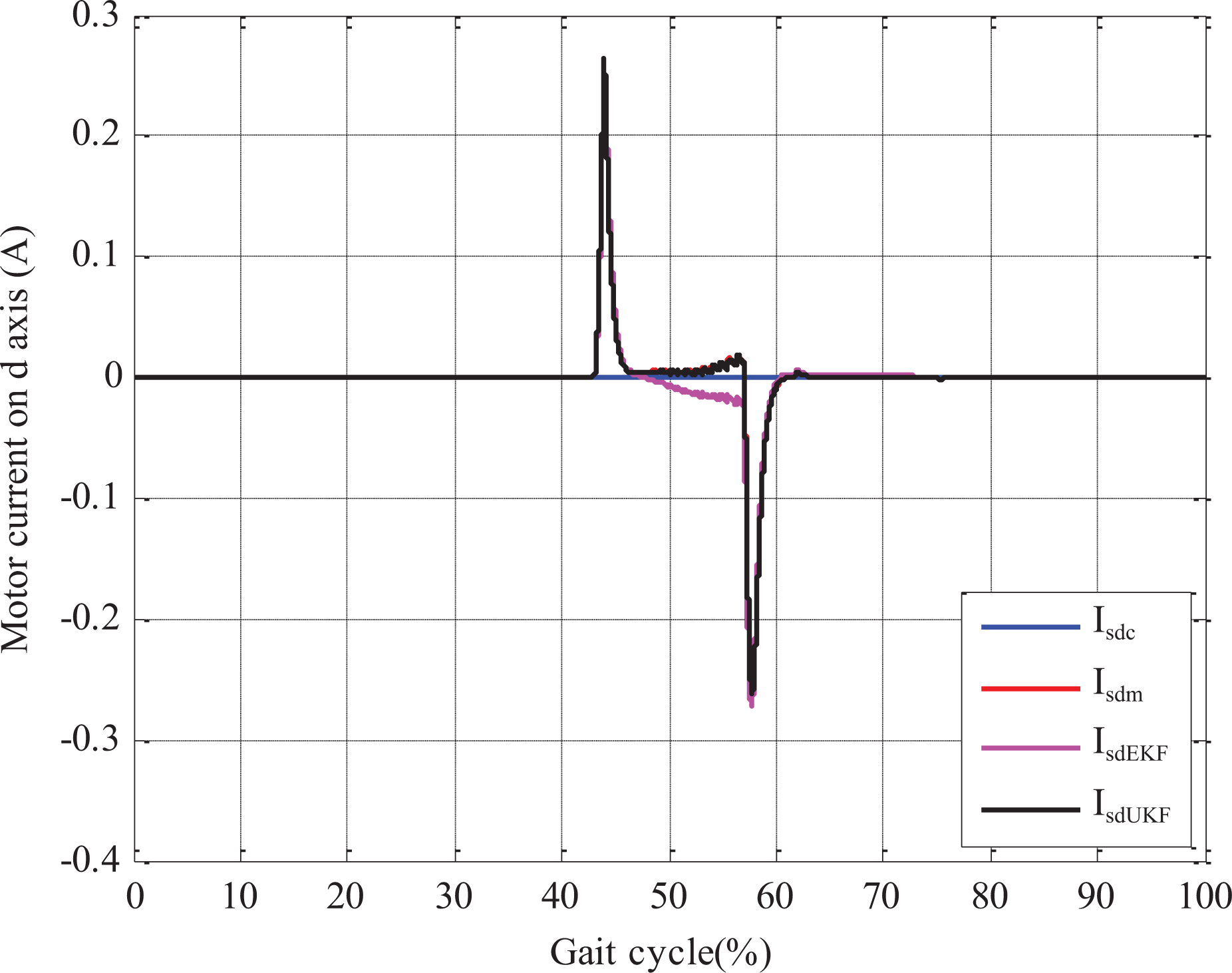
The stator current responsible for machine flux. Blue graph is the current command, red graph represents the measured current, and the magenta and black graphs are the estimated current using EKF and UKF, respectively. EKF: extended Kalman filter; UKF: unscented Kalman filter.

Estimation errors of the stator current responsible for machine flux. The magenta graph represents EKF estimation error, and black graph is UKF estimation error. EKF: extended Kalman filter; UKF: unscented Kalman filter.
Figure 6 illustrates the motor current that is directly responsible for generating mechanical torque. It is clear that the motor is overloaded during PP subsection. Nevertheless, the motor still applicable to the application, and it would be able to operate without any problem as shown in the manual.

The stator current responsible for machine torque. Blue graph is the current command, red graph represents the measured current, and the magenta and black graphs are the estimated current using EKF and UKF, respectively. EKF: extended Kalman filter; UKF: unscented Kalman filter.
The error in the estimation of motor current Isq is demonstrated at Figure 7. For both algorithms, the errors are almost zero. However, it could be observed that the matching of having error in estimation of Isq and the value of Isd (Figure 4). The error of EKF is roughly 10 times more than UKF as a consequence of increase in the system nonlinearity when the current Isd has value not equal to zero.

Estimation errors of the stator current responsible for machine torque. The magenta graph represents EKF estimation error, and black graph is UKF estimation error. EKF: extended Kalman filter; UKF: unscented Kalman filter.
The dynamic model and estimated angular speed of the powered prosthetic are shown in Figure 8. The impedance controller keeps the speed minimum in each subsection, and as the equilibrium point of system angular speed equal to zero, the system act as a spring with damper.

Powered ankle-foot angular speed for one ground level gait cycle at normal speed. Red graph represents the measured angular speed, and the magenta and black graphs are the estimated angular speed using EKF and UKF, respectively. EKF: extended Kalman filter; UKF: unscented Kalman filter.
In Figure 9, the difference between the dynamic model speed and estimated speed based on EKF and UKF are illustrated. The EKF performance is affected by the increase of motor load and the switch of the control system from an impedance controller to position controller. On the other hand, the UKF performance is more stable and the estimation error is between −0.005 and +0.005 (rad/s).
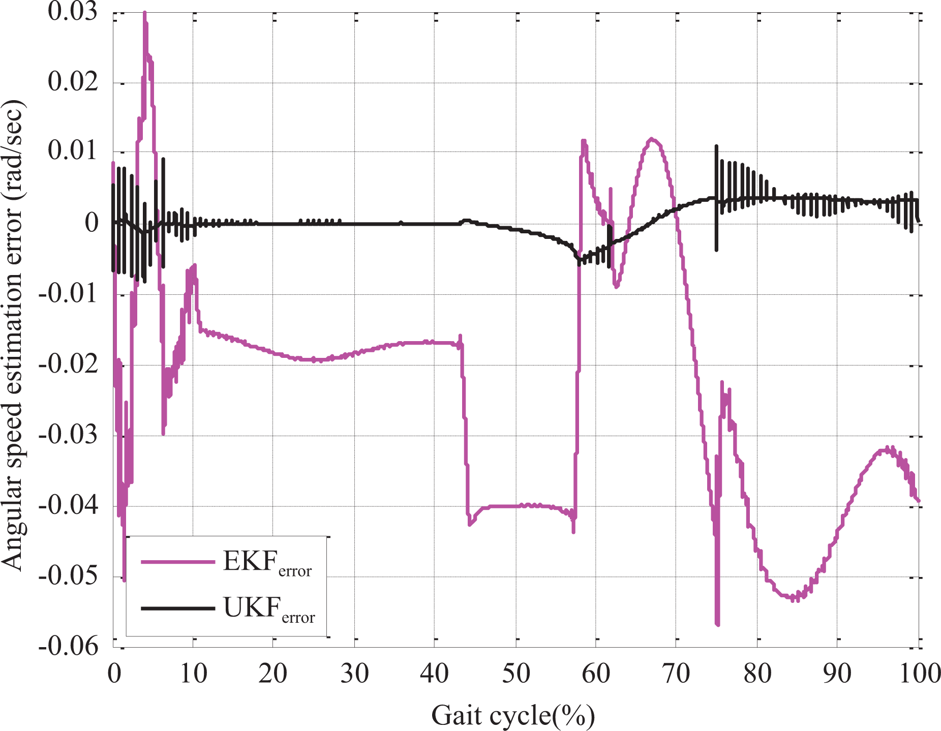
The error in powered ankle-foot angular speed estimation. The magenta graph represents EKF estimation error, and black graph is UKF estimation error. EKF: extended Kalman filter; UKF: unscented Kalman filter.
Figure 10 demonstrates the powered ankle-foot performance compared to sound ankle-foot trajectory in ground level walking at normal speed and the estimated angular position. The control system is not able to track the ankle trajectory especially during PP where the system has a highly nonlinear performance (picks up command torque at the beginning and is almost zero torque at the end, 0.18 s, of this subsection).

Powered ankle-foot angular position for one ground level gait cycle at normal speed. The blue trajectory represents normal subject ankle-foot performance, red graph represents the measured angular position, the magenta and black graphs are the estimated angular position using EKF and UKF, respectively. EKF: extended Kalman filter; UKF: unscented Kalman filter.
The UKF performance is accurate and the estimation error less than 0.3°, but the error of EKF picks up at −2° at the end of the cycle as a result of integrating the estimated speed, which already has an estimated error (Figure 11).

The error in powered ankle-foot angular position estimation. Magenta graph represents EKF estimation error, and black graph is UKF estimation error. EKF: extended Kalman filter; UKF: unscented Kalman filter.
Conclusion
In this article, a theoretical proposal to enhance powered ankle-foot prostheses actuation technique was introduced. Firstly, the commonly used BLDC was replaced with PMSM to reduce the actuator torque ripples and improve actuator ability to be overloaded. Secondly, two model-based observers were developed to predict the PMSM angular speed and position, and then the end effector’s angular speed and position were calculated using the mechanism transmission ratio. The simulation results show an accurate and reliable performance of UKF. Nevertheless, the system nonlinearity and load disturbance influenced EKF performance and the position estimation error reached −2°. The powered ankle-foot prosthesis control system is based on two-level control system to trace biological ankle-foot profile. However, the control system was not able to precisely track (2% gait shifts prior swing phase) the ankle-foot profile as shown in Figure 10.
Future work will be devoted to design control system based on T-S fuzzy logic impedance controller, the controller knowledge base would be developed to identify gait cycle subphases. Utilizing the fuzzy logic controller would enhance system performance by eliminating the switching between states and regulate the prosthesis in smooth continuous manner. Furthermore, the motor’s current controllers (PI) will be redesigned based on an optimal control theory (H2 or H∞) to minimize power consumption.
Footnotes
Declaration of conflicting interests
The author(s) declared no potential conflicts of interest with respect to the research, authorship, and/or publication of this article.
Funding
The author(s) disclosed receipt of the following financial support for the research, authorship, and/or publication of this article: The work has been fund by the grants: Platcom HIP-2, and FG004-17AFR.