
Abstract
In a Robot Operating System (ROS) application, robot software is often distributed across multiple networked components, forming the ROS network, where every component acts as server and/or a client, and publishing and/or receiving robot data simultaneously. For indoor robots, a local ROS network, through a Wi-Fi hotspot, is sufficient. But for outdoor robots, a remote ROS network is needed to connect the ROS application to the cloud. Although a number of cloud-based solutions support this, implementing them is challenging, as they need to be configured to facilitate ROS's unique, multidirectional, and simultaneous flow of robot data. This article presents Port Forwarding as an alternative approach, which offers a private, secured, and a direct ROS-to-ROS, eliminating the need for a dedicated middleware and its configuration and setup complexities. But Port Forwarding has its own challenges; chiefly, the beforehand knowledge of Internet addresses of all networked components and the need to update port forwarding settings when these addresses change, which they often do. This article addresses this issue (and others) and presents a detailed procedure for setting Port Forwarding for ROS applications, highlighting configuration, and troubleshooting steps. Also, the article compares between Port Forwarding and cloud-based solutions, in terms of setup, performance, and others. Results show that robot performance under Port Forwarding is on par with cloud-based solutions, but it required a fraction of setup time. The authors developed a set of shell scripts that monitor the Internet addresses of all networked components and auto-update Port Forwarding settings when they change, solving this issue. With this, Port Forwarding could be considered a viable option for ROS system networks, on par with cloud-based solutions.
Introduction
The Robot Operting System (ROS) is one of the fastest growing platforms for robot software development, 1,2 and one of its many features is software distribution. As often in a ROS application, robot software is distributed over multiple networked components, forming the ROS network shown in Figure 1. In this network, robot data are shared among all connected components, with every component publishing and/or subscribing to this robot data, and ROS’s architecture manages the flow of data, ensuring proper robot operations.
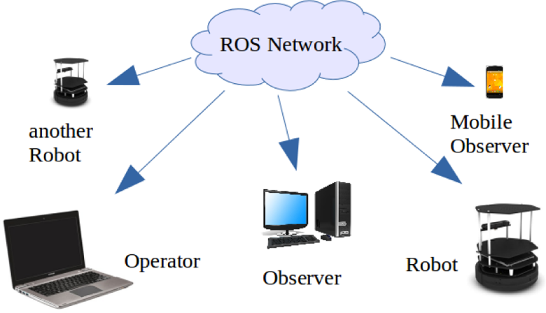
The ROS network. ROS: robot operating system.
For indoor robots, a local ROS network is sufficient, where all components are networked via a local Wi-Fi router. For outdoor robots, however, the situation becomes more challenging. 3 This is where a remote ROS network is needed, where components are networked remotely through the cloud. But due to standard Internet protocols (IPs), the remote ROS network, as shown in Figure 4 below, would not work without further setup. One approach is to create a bridge, or a middle point in the cloud, where robot data are hosted and is accessible to all connected components, allowing them to indirectly interact with each other. A number of cloud-based solutions facilitate this, such as webservers, android, and a number of cloud-robotics platforms, such as RoboEarth. 4 –9
However, utilizing these solutions for ROS applications is challenging; by default, webservers host data and publish it only when requested by clients, such as web applications or android Apps. But in a ROS network, every component acts as client and/or a server, publishing and/or receiving robot data. Therefore, cloud-based webservers need to be configured to act as simultaneous clients and/or servers to facilitate the multidirectional and simultaneous flow of robot data needed in a ROS network. 10,11 Other factors need to be managed as well to ensure proper robot operations, such as security, privacy, concurrency, and time delays.
This article presents an alternative solution, portforwarding (PF), which offers a secure, private, and a direct ROS-to-ROS remote connection, without the need for a middle ware, eliminating the need to configure a third party technology for ROS. Furthermore, PF is also scalable, as it allows application updates without further setup, something cloud-based solutions cannot achieve, as will be shown below. However, PF has its own challenges and limitations.
This article begins by reviewing cloud-based solutions, highlighting pros and cons. Then, the article presents a detailed procedure for implementing PF for ROS, highlighting configuration, and troubleshooting steps. Finally, the article compares between the two solutions, in terms of setup, performance, and challenges of each method.
Literature review
ROS provides the needed tools to link its applications to the cloud, such as the
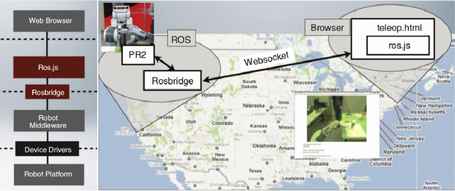
Rosbridge and RobotWebTools in action. 4
But as the figure shows, rosbridge is just a small component of the software developed to make this happen. After all, rosbridge only links ROS and non-ROS clients, but these non-ROS clients still need to be developed. They need to perform ROS operations (e.g. robot operations, sensor management, visualization, etc.) in a non-ROS environment. In the example above, the web application interacting with ROS, which utilizes the ROS.js library, the implementation of ROS in JavaScript, is still needed to be written by the developers. Furthermore, the teleop example shown above is a very simple ROS application that requires very few message types to be transmitted, such as Geometry_msgs/Twist, which defines robot speed. Therefore, the ROS.js code needed to achieve this is relatively simple. But in a typical ROS application, there are tens to hundreds of message types being transmitted simultaneously in all directions, describing various aspects of robot operations, such as robot speed, location, sensor data, odometry, and so on, and each of these message types must be transmitted individually or their meanings would be lost. In other words, each of these message types requires its own bridge to be remotely transmitted, see Figure 5, which only adds to the complexity.
Another cloud-based solution is
Researchers recognized these challenges and introduced a number of cloud-robotics platforms to streamline the process of linking ROS applications to the cloud. These include RoboEarth, RobotWebTools, and others. 7 –9 In fact, Figure 2 shows the architecture of RobotWebTools, while Figure 3 shows the components of RoboEarth.

Components of RoboEarth. 7
However, these platforms have limits. The best way to describe these limits is by an analogy; consider rosbridge and cloud-robotics platforms as manual and automatic transmission in car; and the automatic transmission provides a bit of convenience, but the driver still needs to drive the car. The same thing applies in cloud-robotics platforms; while they do provide the scaffolding that links between the various technologies discussed above, developers still need to learn how to use these tools and then develop the necessary applications that use these tools. For example, the RoboEarth platform is built of several components such as Rapyuta, KnowRob, WIRE, and so on. So, when using this platform, one must learn each of these individual components as well as their base technologies, which happen to be rosbridge, webservers, database design, web application, and so on. Also, these platforms can never fully predict the individual needs of every robot application (e.g. message type to be transmitted, etc.), and so developers could end up coding and setting many of these components after all. Finally, utilizing these open source platforms brings concerns over data security and privacy, as robot data would be exposed to anyone with access, which could be undesirable for proprietary and private applications.
Port forwarding for ROS applications
As discussed above, the remote ROS network would not work without further setup. That is because each modem/router acts as a gatekeeper that blocks any incoming remote requests from accessing local components. This is a security protocol designed to protect the local components from remote attacks or unwanted intrusion. Because of this, the robot and laptop in Figure 4 can only recognize the routers of each other but not each other. So, if the laptop attempts to contact the robot, it would not be able to do so, because the robot’s router blocks that connection and vice versa. In cloud-based solutions, this problem was solved by creating a middle point in the cloud, such as webserver, where the robot and computer would share and indirectly interact with each other. But as discussed above, this extensive websever setup is required to facilitate ROS’s multidirectional and simultaneous flow of robot data.
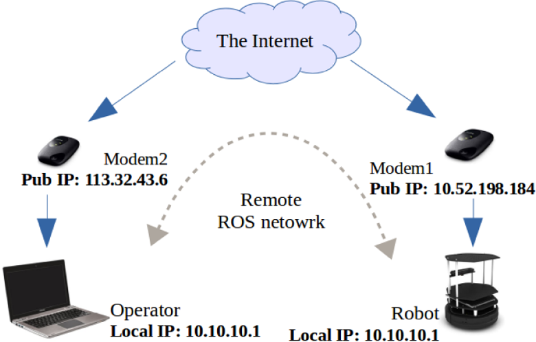
The remote ROS network. ROS: robot operating system.
PF offers an alternative solution, by allowing incoming remote requests to be forwarded from the routers to the local components, which allows remote access. 14 So in the above example, the robot and laptop would be able to recognize each other directly, without a middle point or a third party solution, establishing the remote ROS network. 15 Today, PF is used for pin-point remote access of game servers, to bypass proxies, to create secure and private networks, to remotely access Intranet and other private networks remotely, and to remote access hardware devices such as home computers and surveillance cameras.
Another great advantage of PF over cloud-based solutions is shown in Figure 5. As discussed above, due to the need of a middle point, or bridge, every message type in the ROS application requires its own bridge when transmitted through the cloud. In PF, this is not necessary.

Cloud solutions versus port forwarding.
PF does not require a bridge or a middle point, instead it creates direct ROS-to-ROS channel as if the connection was local, alibi with time delay. This allows any and all message types of the ROS application to be transferred. Also, future application updates or modifications would not require any further setup.
For example, if a new sensor was added to the robot in Figure 4 was modified, then the cloud-based solution would need to be reconfigured to accommodate the new bridges needed to transmit the new sensor’s message types. But in PF, once the initial setup is done, then any new updates or modifications are supported without further configuration.
Challenges to implementing PF
On the other hand, implementing PF comes with its own challenges. First of all, implementing PF is a
Secondly, PF requires the
Thirdly, implementing PF for corporate connection (company or university) would
Fourthly, due to the mobile nature of outdoor robots, conventional virtual private networks
Finally, ROS tutorials
Methodology
A successful ROS network, local or remote, that consists of a group of components (robots, computers, mobile devices, and others), must fulfil the following
10,11
requirements: There must be a complete, bidirectional connectivity between all components, on all available ports. Each component must advertise itself by name that all other components can resolve. One of these components is declared the ROSmaster of the network (usually the main robot). All ROS packages, distributed over this network, must be configured to use this ROSmaster.
All the settings and configurations discussed in the sections below are designed to fulfil these requirements. The following sections are divided into three parts; the expected outcome, the configuration steps, and the verification steps. The meaning of these parts should be self-explanatory. Also, because each component is linked to the Internet through a separate modem in a remote ROS network, the following settings must be implemented on each modem, and its connected component. For example, in Figure 4, the laptop is connected to the internet through modem2, therefore, the following settings must be performed on modem2 and the laptop. Similarly, the settings below must also be performed on modem1, the robot (through its netbook), and so on.
Step 1: ISP Settings
As discussed above, there are generally three types of ISP connections, corporate, home, and telecom connections, and so the settings for each connection type are discussed below.
Expected outcomes
Obtain confirmation from ISP that PF is enabled to your connection, on
Obtain a public IP address for your modem that will be used by others in the remote ROS network.
By default, the router/modem is usually provided by the same ISP, and so this and the following steps, ISP and router/modem settings, are usually performed concurrently. Nevertheless, there are important factors that the user must understand before selecting a suitable telecom ISP for PF, which is discussed below.
Configuration steps
The configuration steps discussed below vary for each type of connection, specifically:
Corporate connection
The user must contact the IT department, specifically the network administrator to obtain permission to use PF on all ports. Once that is accepted, the IT department would usually help configure it and assign the modem a fixed IP address. PF is usually meant for a specific port, hence the name port forwarding. But since ROS requires all available ports be used, the term used here is DMZ, which is basically PF to any available port. Also, corporate connection usually uses a local area network (LAN)-cabled connection, and the user would need a router to establish a wireless network for ROS component. Therefore, configuration of the router with PF (to all ports) could also be handled by the IT department as well.
Home connection
By default, there is no need for a permission for this type of connection, but it does not hurt to contact the ISP, and confirming the PF is indeed enabled. Also, the public IP address is usually the IP address of home router/modem.
Telecom connection
Unlike corporate and home connections, telecom connection is the only true mobile connection, which is ideal for outdoor mobile robots. Corporate and home connections are useful for experimenting indoors. Telecom ISPs either provide portable wireless modems/routers or the user’s mobile phone can be used, through the tethering and portable hot spot features. Either approach provides a portable wireless connection. As such, the user must contact the ISP to enable PF, however, when contacting a telecom ISP, one must remember the following pitfalls: It is possible that the general tech support are not well trained on PF, so request to speak to the more technically trained networking department, or arrange an appointment. Not all the telecom ISPs support PF and some support it partially through specific types of portable modems and specific types networks. The ISP may or may not provide a fixed public IP address, in the event the IP address is not fixed, the user must put that in mind when performing later configurations steps.Another issue to consider is the coverage area offered by the ISP, connection speed (3G or 4G), cost of subscription, and similar factors.
Once all that is done, the provider would supply the user with a device that supports a wireless connection (portable or grounded), which also supports PF on all ports, with a fixed or changing public IP address.
Verification steps
In reality, and as discussed above, the first two steps (ISP and modem/router settings) are usually performed concurrently. As such, there is no verification at this point and the actual testing begins after the router/modem has been configured, which is the next step.
Step 2: Router/modem settings
As discussed before, the purpose of PF is to configure the modem/router to forward remote requests to members of the local network.
Expected outcome
There is only one expected outcome here: obtaining an “Open” status when checking for PF through any available and open port. Once the router/modem is configured, the connection and PF are tested using online PF testing tools. These are used to check the success or failure of the configuration. For a modem/router provided by a telecom ISP without a fixed public IP address, this has to be verified a multiple times through multiple IP address, as discussed below.
Configuration steps
Corporate connection
Usually, the network admin would perform this step concurrently with the first step (ISP setting). That is, the IT department of the corporation or Uni would usually enable PF and configure the modem/router.
Home and telecom connections
Using a browser, log into the router/modem’s homepage, navigate to firewall settings, and enable PF, DMZ, and other filtering features shown in Figure 6.

Router/modem settings: port forwarding.
In order to forward remote requests from modem1 to the robot, as shown in Figure 4, the modem is configured to forward these remote requests to the local IP address of the robot, which is the IP address value shown in Figure 6. This is very important, if the local IP address of the robot changed for some reason, then the user must come back here and reconfigure the router. Alternatively, the local IP address (in this case 10.10.10.1) can be permanently reserved for the robot and so no reconfiguration is required. Since all available ports are required by ROS, the range was set as shown in Figure 6. As it can be seen in the figure, this router also support DMZ, which could be easier to setup, but not all ISPs provide a separate page for DMZ, if not, then the settings shown in Figure 6 would suffice. In the event that the router/modem is not provided by the ISP, then the router’s manufacturer’s support resources would be consulted, such as the online resources for D-Link, Netgear, or others manufacturer’s websites.
Verification steps
An important point to remember here, ports must be allowed open and available by the ISP or network admin before attempting to configure the modem/router. Therefore, this must be verified by the ISP before testing these steps. To verify that PF and/or DMZ settings have been correctly configured, follow these steps: First, ensure your connection is working, open a browser, and browse the internet. If OK, then proceed. Select a port number between 1024 and 65000, let us call this value: portNumb. Start a netcat chat session on the selected port. In Linux, run: For example, if you chose portNumb = 12345, the command would be: This will start a netcat server at the portNumb you selected (you can try Open a new browser window, search for any PortChecker website, and then go to it. In the website, you will see your modem’s public IP address, and a space to enter the number of the port you wish to check, enter the number, and hit OK or Go. If the status of the port is Open, then this step is successful, and you can proceed to step 3. Repeat the test with different portNumbs to confirm that your PF works on any port.
This test puts the component being configured (robot, computer, etc.) in a situation that mimics the remote ROS network (Figure 4). The netcat command mimics the ROSmaster service, while the PortChecker website mimics the signal received remotely from other components. The ideal result expected here is Open, which indicates that everything is set properly. In the event, the result is Closed, and there are two possibilities, as shown in Table 1.
PortChecker test results and their meanings.

As shown in the table, the user must ensure that the netcat server is up (command has been typed in a terminal), otherwise the selected port would not be used. However, if the netcat server was indeed up, and the result is still Closed, this means PF setup and configuration has not been done correctly. This could be due to three possible reasons. Port is being used by another service on the network, try another port numb (higher than 1024). There could be firewalls and/or network limitations by the ISP or network admin, return to step 1. Modem/router PF configuration was not properly performed, return to step 2.
Once the result is Open to all components of the remote ROS network, as shown in Figure 4, then this step is complete and you can proceed to step 3.
Step 3: Linux OS settings
From this point onwards, all configuration steps are within the computer level (PC, laptop, netbook, etc.), therefore, from now on, the term component refers to the computer of the item being networked in the ROS network. For example, referring to Figure 1, this could be the Desktop of the observer, the laptop of the operator, the netbook onboard of robot1, and so on. Also, this article assumes that Linux is the operating system of all of these components. However, the settings discussed below are generic and so they can be applied in any other ROS-supported operating systems.
Expected outcome
At the end of this step, network components are expected to: Ping each other, using network names. Secure SHell (SSH) to each other, using network names. Netcat chat with each other, using network names, initiated from either side, and on any port.
These three tests check for important features used by ROS. Recalling that in a ROS network, components must recognize each other and exchange data in order to facilitate the performance of the robot. These steps verify that. In the last test, it is important that the netcat chat session should be successful when initiated from either side. That is because in a ROS network, every component is expected to initiate an exchange of data and act like a publisher and/or subscriber.
Configuration steps
For each component of the remote ROS network (Figure 4), do the following: Take note of the local and public IP address of the component. For example, the laptop in Figure 4 has a local IP add = 10.10.10.1 and a public add IP = 113.32.43.6. Access the file that defines local hosts in your OS. In Linux, run: Edit that file as shown in Figure 7 below. Ensure that you key-in the correct IP addresses. Take note of the discussion below. Save, close, and restart. Repeat this step for each component.

Local hosts configuration—in the laptop.
The hosts file is a Linux environment file that registers names and IP addresses of each component. As shown in Figure 7, the laptop is defined as sami and the robot is defined as turtlebot, where these names are completely arbitrary.
The hosts definitions must be created for each component and from its point of view. Figure 7 shows the definitions from the laptop’s point of view, where it is defined by its local IP address, and robot is defined by its public IP address. From the robot’s point of view, as shown in Figure 8, the situation is reversed. The robot is now defined by its local IP address and the laptop is now defined by its public IP address.

Local hosts configuration—in the robot.
Also, notice how the names sami and turtlebot are the same in both hosts definitions file. This is actually a convenience, and it is indeed recommended to be the same. Because technically these components could be assigned different names in different hosts files, but that would make networking far more complicated. Apart from this, there are several pitfalls and challenges that could arise here, which are discussed below:
gedit might not work
The command
Changing networks
Hosts definitions are valid for the network they are part of. As can be seen in Figures 7 and 8, public IP addresses are being used, which is only true for a remote ROS network. If a user decides to switch to a local network, where only local IP addresses are used, these definitions can no longer be used and other definitions need to be defined.
Furthermore, the component (robot or laptop) could be used in different networks in different times, changing from a corporate network to a remote network to a local-telecom network (robot and laptop using the same portable telecom modem/router). In every one of these networks, the IP addresses would change.
Therefore, it would be useful to create a hosts definition file that caters for all these changes, one example of such file is shown in Figure 9.

A complete hosts file configuration.
As it can be seen in the figure, there are several sets of hosts configurations that can be applied, depending on the type of network currently used. There are two local networks (office and portable) and a remote network. The local network use local IP address, while the remote network uses public IP addresses. Finally, this file is from the laptop’s point of view, and so a similar file should be created for the robot’s point of view.
Dynamically changing IP address
As discussed above, ISPs may not allocate you a fixed public IP address. If so, you will need to update the hosts file every time you restart the portable modem, this could be cumbersome and error-prone. The solution is to automate this step using a combination of shell scripts and a cloud storage facility, such as Dropbox. Through this setup, the robot’s netbook can enquire about its current public IP address, informs the laptop (through Dropbox), allowing the laptop to update its hosts file. The scripts used for this project, developed by the author, can be found on this repository. 18 In the discussion section below, these scripts and their inner workings are further discussed.
Verification steps
There are three tests to be conducted here: the ping test, the SSH test, and the netcat chat test. All the three are conducted through the remote network. Note that the names and IP addresses used in the test below are based on the settings saved in the hosts files in the laptop and the robot of the author, use the your own names and IP address in your tests. The ping test is as follows:
In the laptop’s terminal, run: If you used a different name for the robot, use it. If successful, run the same test from the other side. If successful, then you can proceed to the SSH test.
Figure 10 shows an example of a successful outcome, where the laptop was able to ping the robot through the remote network using only the host name. As it can be seen from the figure, the public IP addresses are in effect (partially hidden).

A successful ping test, through the remote network.
The SSH test
SSH from the laptop to the robot using a command similar to the one shown in Figure 11. If successful, run the same test from the other side. If successful, then you can proceed to the netcat test.

A successful SSH test, through the remote network.
It is possible that the SSH test could fail due to reasons related to SSH itself and not anything discussed so far. Issues are such as public key, username authentication, installation issues of SSH, SSH being down (switched off), and other related factors. Therefore, run the SSH test on a local network first. This would require you to reconnect robot and laptop through a single modem and update the hosts definitions to reflect this change. Then attempt to SSH between robot and laptop, and then deal with SSH-related issues, and once resolved, then you can proceed to run this test on a remote network. Figure 11 shows an example of a successful outcome, where the laptop was able to SSH the robot through the remote network using only the host name.
The netcat chat test
In the laptop, open two terminal windows. In one window, SSH to the robot Now you have two terminal windows open, one for the robot and one for laptop, as shown in Figure 12. In the laptop’s window, run: In the robot’s window, run: If OK, then you created a chat session, type a away in either window, you should see it on the other side. If successful, then repeat step 3 from the robot’s window and step 4 from the laptop’s window. If both sides are successful, then step 3 is complete, and you can proceed to the final step (step 4).

A successful netcat test, through remote network.
Once again, portNumb is the port number you chose, which could be any available port above 1024. Figure 12 shows an example of a successful outcome. In the figure, we can see a chat session established in the robot’s side. The chat session was successfully established from the laptop’s side as well.
It is important to understand that step 6 of the test is very important. One must ensure that the chat server can be established on both sides, because that represents the ability of each component to act as a server and a client, which is a fundamental requirement for ROS components.
Step 4: ROS settings
This is the final step in the configuration and so the reader is advised to ensure all previous steps are completed successfully before attempting this step. The objective of this final step is to register all components of the remote ROS network with the ROSmaster and insure that all components are able to publish and subscribe to each other. A ROSmaster could be any component of the ROS network. For the network shown in Figure 4, the robot was selected as the ROSmaster. Therefore, the expected outcomes would be as follows.
Expected outcomes
The ROSmaster component is properly registered for each member of the ROS network.
Every component is able to publish or subscribe to other components in the remote ROS network.
This can be achieved by appending the bash file, the shell environment file, and setting the value of ROS_Master_URI to equal the IP address of the ROSmaster, or specifically:
Configuration steps
In the ROSmaster component, add the following:
In other components, add the following:
Do not add definitions of
Public versus local IP addresses
Once again, since the ROSmaster (robot) refers to itself, we use the robot’s own local IP address. If we attempt to use the public IP address here, roscore would throw an error and would not start.
As for other components, such as the laptop, they will refer to the robot using its public IP address. This is very similar to the hosts definitions created in step 3.
ROS_IP and ROS_HOSTNAME
ROS networking tutorials 10,11 recommend setting these values in order to solve networking issues. However, it was found by the author that doing so would cause ROS problems; some components would be able to publish only and not subscribe, or vice versa; subscribe only and not publish. One must remember that these tutorials were written primarily for the local ROS network, where these settings would be fine. But for the remote ROS network, these definitions would override the hosts definitions created in step 3 (Linux settings) and so cause the ROS problems discussed above.
As such, for the remote ROS network, the authors recommend using the ROS_MASTER_URI only and set the hosts as discussed in step 3.
Changing IP address
If the robot’s public IP address is variable, then once again, the bash settings in each component must be updated every time the robot’s portable modem is restarted. Once again, this step could be automated, as discussed in step 3, through the use of shell scripts and a cloud storage facility such as Dropbox. In fact, the scripts developed for this project, 18 referenced above, automate this step as well.
Verification steps
At this stage, all settings and configurations have been completed, and to verify the settings, the remote ROS network needs to be started and tested. There are three ROS tests that can be used here: the minimal network test; the listener/talker test; and the turtlebot interaction tests.
These tests are designed to test specific ROS funtionalities, which are outlined and discussed below.
The minimal network test
Switch on all the modems, and ensure connection is ON.
Update the hosts and the bash files to reflect the current public IP address of the robot.
From the robot’s onboard computer, open a terminal window and run:
Alternatively, SSH into the robot’s onboard computer from another component, and start ROS.
At this point, the remote ROS network is up.
From the laptop, run:
If you see a list of topics, then this test is successful, and you can proceed to the next test.
The listener/talker test
From the robot’s computer, start a talker, buy running this command:
From the laptop, start a listener, by running this command:
If all is OK, the listener on the laptop should respond to the talker from the robot’s computer.
Again, this might longer than usual to happen.
If successful, repeat this test from the other direction, a talker from the laptop and a listener from the robot.
It does not matter who starts first, a talker or a listener, and it should always work regardless.
If successful, then this test is successful, and you can proceed to the next step.
The turtlebot interactions tests
If you have reached this point, then that remote ROS network has been successfully configured. The final test is to implement it on an actual robot. The following test assumes that the robot is a ROS-enabled robot, which means that it has already been preinstalled with the required ROS packages needed to interact with other ROS components. For this article, Turtlebot2 is used. Also, the reader is expected to be familiar with ROS, its concepts, and the terminologies used in this test. Before starting, ensure that all the modems are switched on, that the network is up and running, and that you updated all hosts and bash files to reflect the current IP addresses of the robots. In case you automated this step with dynamic direct domain system (DNS), double check the values for good measure. Then, if all is set, then you can begin the final test. Using roslaunch files, bring up the robot (minimum). From the laptop, start a keyboard teleop session. From the laptop, start an rviz visualization session. In rviz, add a camera view to receive a live feed. Change the image quality to be compressed, or black and white, to reduce burden on the network. When everything is open, proceed to teleoperate the robot (publish) and receive live visual feed (subscribe).
If you are able to teleoperate the robot and receive live images from it, then Congratulations! You have successfully configured your ROS remote network via PF.
Discussion
In this section, an outdoor ROS application is to be linked to the cloud, using a number of cloud-based solutions and PF, with the following settings: The robot is a mobile (wheeled) agriculture robot. It is set to operate in an open field, performing a set of pre-programmed autonomous agriculture tasks.
For an effective performance of this robot, a remote ROS network is developed, similar to the one shown in Figure 4, using the following technologies: rosbridge, ROS-android, RoboEarth, and PF. Through this remote network, the robot sends real-time status and task updates to the operator. Who would use this data to monitor, control, and select the needed agriculture task for the robot to perform.
Data published by the robot are current robot speed, current location in the field (global positioning system [GPS], fix), live feed (camera view of the robot), battery and power status, task status, and task completion.
For example, Figure 13 shows the setup of the ROS-android method, showing the rosjava publishers and subscribers (developed by the authors) to publish robot data, user commands, and establish connectivity, as required. Other methods followed similar setup and patterns.
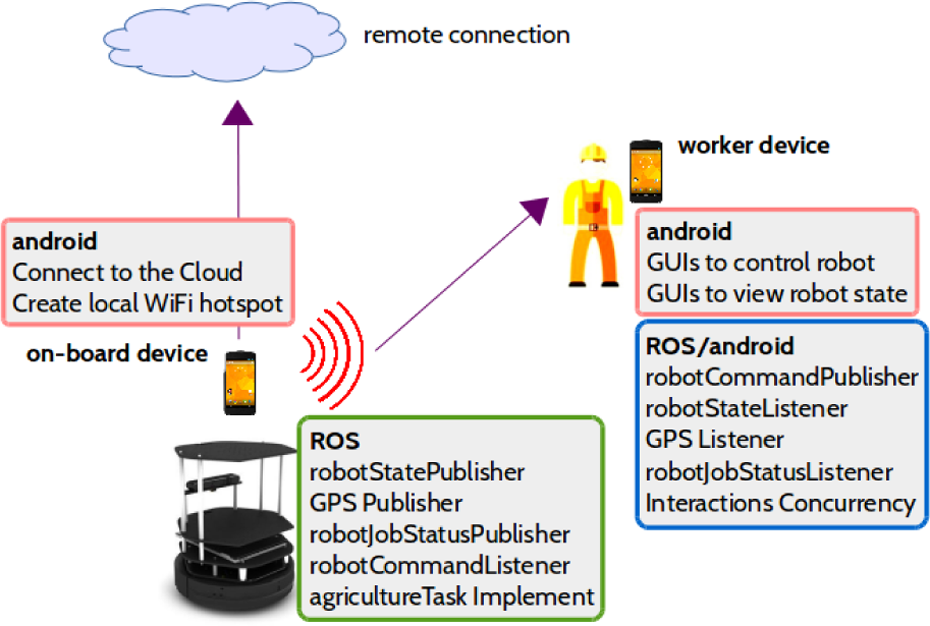
Setup of the ROS-android method.
Then, these methods are compared in terms of setup complexity and effort required, robot performance (utilizing the remote network), and challenges facing implementation of each method (and how to resolve it). The findings of this comparison are discussed below.
Setup complexity
For this work, setup complexity is measured by the amount of man-hours needed to learn, install, and develop the software needed for each method. This is shown in Figure 14 and Table 2. The man-hours needed for ROS and networking were excluded because they are common to all.

Man-hours needed to develop each method.
Software needs for each method.
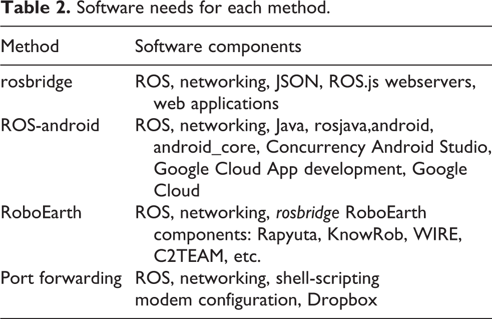
As it can be seen, PF required the least amount of man-hours to learn, install, and develop. This is understandable, considering that it does not require any third party technology or platform. On the other hand, RoboEarth required the most man-hours because developers need to learn all of its components, as shown in Figure 3, which in turn require learning all the basic concepts such as rosbridge, websevers, web applications, database design, and so on.
Also, ROS-android also required extensive learning as it involves learning of Java, and android app development, along with its advanced concepts.
Robot performance
Effect of each method on robot performance can be measured in robot response time. If a method causes too much delay, then it becomes impractical. Through ROS logging, time of robot commands (when given by users) and time of robot execution of these commands were recorded, and by calculating the difference between them, robot response time was found. Figure 15 shows robot response times in each method, while performing a set of robot operations.

Robot remote response time
As shown in the figure, robot performance is comparable in all methods. So, regardless of the method used, the robot performed autonomous tasks the fastest and sensor-related tasks, such as mapping and localization, the slowest, since the robot needed to transmit sensor data to the home computer, remotely, for processing.
An unexpected challenge faced by the authors, when developing cloud-based solutions, was the need to recreate ROS’s visualization tools such as rviz but in non-ROS environments. This meant more development effort was needed to develop these visualization and monitoring tools for android, RoboEarth, and web applications.
In ROS-android, this was solved by utilizing android’s views such as ProgressBar, ImageView, MapView, and so on, as shown in Figure 16. These views allowed users to view robot’s battery status, speed (currently not moving), GPS fix (shown in a google map), and current job status (current task highlighted in blue). Also, control buttons were added for users to interact with the robot.

Agribot App and MapView.
For PF, there was no need for such extra work, as PF allowed a direct ROS-to-ROS connection, so ROS’s visualization tools were utilized as if the connection was local. The only difference was the minor time delays.
Managing dynamically changing IP addresses
As discussed above, ISPs seldom provide users with fixed IP addresses, instead they usually provide a range of IP addresses, such as 173.17.XXX.XXX, where the XXX could range from 000 and 255. This is obviously a problem for PF, as the settings outlined above would need to be updated every time the IP addresses change. The solution to this challenge is to auto-update PF settings through a combination of shell scripts, combined with a cloud-storage facility such as Google’s Dropbox. This is shown in Figures 17 to 19.
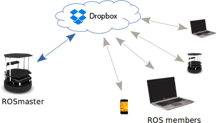
Auto-update PF settings.
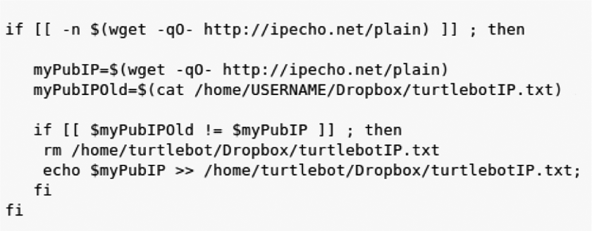
Auto-update PF settings, master-script.

Auto-update PF settings, member-script.
The process begins with the ROSmaster component of the ROS network, which hosts the ROS session and manages the flow of information across the ROS network, ensuring all components transfer their data to the right destinations. In this example, the ROSmaster happens to be the agriculture robot, and there is only one other member, the operator’s laptop.
The master-script is installed in the ROSmaster’s embedded computer and runs when the robot is started. It first checks for internet connection, then it checks the current public IP address. If there is any change, then it updates the value stored in a file saved on Dropbox. Because all ROS members are linked to the same Dropbox file, they all get notified when the file is modified (when the IP address is updated). This in turn triggers the member-scripts (Figure 19).
Similarly, the member-script checks for changes in the IP address of the ROSmaster, which is indicated by changes in the Dropbox file. Once triggered, then the PF settings for the member (laptop) are updated. This is done by updating hosts and the ROS_master_URI, which are steps 3 and 4 of the PF configuration process, as discussed above. But, Figures 18 and 19 show simplified versions of these scripts, where all prompts, confirmations, and the complete two-way PF settings update are shown. The source code of the complete scripts are available at the Github page of this project. 18
To summarize the discussion section, PF-powered robots performed on par with robots powered by cloud-based solutions, while requiring the least amount of time to learn, install, and develop. The shell scripts developed by the authors were able to monitor the IP addresses of the networked components and auto-update PF settings accordingly, allowing PF to become a viable option for linking ROS applications to the cloud.
Conclusions
In conclusion, this work was able to meet its objectives. Cloud-based solutions for linking ROS applications to the cloud were reviewed, a detailed process for setting up PF for ROS was introduced, and a comparison between the two methods was made.
Although cloud-based solutions do deliver on their promise, they come with challenges. This is because linking cloud-based solutions with ROS requires building a
A detailed process for configuring PF was presented in this article, highlighting all configuration steps, and in all of its layers. This includes the ISP level, the modem/router level, the Linux level, and finally ROS itself. Along the way, troubleshooting protocols were introduced to help developers test their steps and ensure proper configuration and robot operations.
One of the biggest challenges facing PF is handling dynamically changing IP addresses. Since most ISPs provide ranges of IP address and seldom fixed ones, PF settings would need to be updated accordingly and doing so manually would be cumbersome and error prone. To solve this problem, the authors introduced a collection of shell scripts, combined with some cloud-storage facilities (ironically) to auto-update PF settings of all networked components. This is achieved by monitoring the connection, detecting changes in IP addresses, and then updating PF settings seamlessly.
Performance-wise, robot systems utilizing PF performed on par with those utilizing cloud-based solutions, but with the fraction of the man-hours needed for learning and setup. This was the case because PF provides a direct ROS-to-ROS remote connection, without the need for a third-party bridge, and its associated challenges such as data conversion, non-ROS development, and so on.
Therefore, with the work presented in this article, PF could be considered as viable option for setting up of remote ROS networks and ROS-enabled outdoor robot applications such as agriculture, military, search and rescue, and others.
Footnotes
Acknowledgement
The authors would like to thank the College of Engineering, the Innovative and Research Management Centre (iRMC), UNITEN, for their continued support of this work.
Declaration of conflicting interests
The author(s) declared no potential conflicts of interest with respect to the research, authorship, and/or publication of this article.
Funding
The author(s) disclosed receipt of the following financial support for the research, authorship, and/or publication of this article: This work was supported by the College of Engineering, the Innovative and Research Management Centre (iRMC), UNITEN and the Ministry of Higher Education, Malaysia through research grant (20140127/FRGS/V3500).