
Abstract
A variety of open-source software tools are currently available to help building autonomous mobile robots. These tools have proven their effectiveness in developing different types of robotic systems, but there are still needs related to safety and efficiency that are not sufficiently covered. This article describes recent advances in the Aerostack software framework to address part of these needs, which may become critical in the case of aerial robots. The article describes a software tool that helps to develop the executive system, an important component of the control architecture whose characteristics significantly affect the quality of the final autonomous robotic system. The presented tool uses an original solution for execution control that aims at simplifying mission specification and protecting against errors, considering also the efficiency needs of aerial robots. The effectiveness of the tool was evaluated by building an experimental autonomous robot. The results of the evaluation show that it provides significant benefits about usability and reliability with acceptable development effort and computational cost. The tool is based on Robot Operating System and it is publicly available as part of the last release of the Aerostack software framework (version 3.0).
Keywords
Introduction
According to Kortenkamp et al., 1 the executive is the system of a robot control architecture responsible for translating high-level mission plans into low-level behaviors, invoking behaviors at the appropriate times, monitoring execution, and handling exceptions. The executive is a component of autonomous robots that is especially critical since its characteristics may affect significantly the quality of the final robotic system in aspects such as reliability and efficiency.
To facilitate the construction of the executive system, developers can use software tools that are freely available. These tools are different, for example, in the way they represent mission plans. For instance, there are tools that formulate mission plans using representations based on finite state machines such as SMACH, 2 rFSM, 3 RAFCON, 4 and FlexBE. 5 Some tools use behavior trees such as the ROS behavior_tree package 6 and BehaviorTree.CPP (MOOD2Be Project). Other solutions use declarative or functional symbolic representations that facilitate the use of automated planners. For example, ROSPlan 7 uses PDDL and CRAM 8 uses Lisp and Prolog.
These tools effectively help to build autonomous robots, although there are still difficulties that have not been sufficiently addressed and may affect efficiency and reliability. The execution of a mission should be robust enough to handle factors such as the presence of unexpected events in the environment, user specification errors in the mission plan, and interruptions due to preemptive interaction between the user and robot. This is particularly significant in aerial robots, which normally require reliable solutions to avoid dangerous behaviors during flights that can produce serious consequences. In general, there are different approaches in robotics that try to deal with these factors. 9 However, we have not found available open-source software tools that solve these issues with sufficient efficiency to be able to operate on board aerial vehicles.
This article describes recent advances in the Aerostack software framework to address this need. We have designed a new method for Aerostack that divides the execution control of a mission plan into different processes with separate functions (plan interpretation, safety monitoring, behavior coordination, belief management, etc.). The solution is presented in form of a model of executive system formulated as a software architecture with a set of reusable open-source components (based on ROS—Robot Operating System). The model has been tested with the help of aerial robots, although it has been designed to be independent of the type of robot.
The remainder of the article is organized as follows. The second section describes the Aerostack software framework for which the presented solution has been created. The third section presents the specific components of Aerostack used for building executive systems. The fourth section shows the evaluation of the presented solution that analyzes the benefits (about usability and reliability) and the costs (about development effort and performance efficiency). The fifth section compares our solution with related work and, finally, the sixth section presents the conclusions.
The Aerostack software framework
Aerostack (http://www.aerostack.org) 10 is a software framework for aerial robotics that has been developed in our research group Computer Vision and Aerial Robotics at Universidad Politécnica de Madrid. This framework, based on ROS, provides a library of open-source software components specialized in aerial robotics and a general combination mechanism using an architectural pattern to build the control architecture.
Aerostack has been used in the development of complex robotic systems related, for example, to natural user interfaces, 11 surface inspection, 12 coordinated multi-robot systems, 13 landing on moving platforms, 14 search and rescue missions, 15 and altitude estimation in complex dynamic environments. 16
Figure 1 shows the reference architecture of Aerostack as it is defined in the last release (version 3.0). In the figure, circles represent data processing units (or processes in short) that are implemented as ROS nodes (a duplicated circle represents several processes of the same type). Processes are organized in three main layers: interface, functional, and executive. The interface layer includes processes that help interact with the world. They include processes that receive data from sensors or send commands to robot actuators, as well as communication processes with the human operator and other robots.

The Aerostack reference architecture (version 3.0).
The other two layers, functional and executive, are common in multilayer architectures of autonomous systems, as can be seen in the LAAS architecture, 17 Claraty, 18 or in the general description of Kortenkamp et al. 1 The Aerostack architecture uses a standard communication channel, which is implemented with ROS message types that are common in aerial robotics. This channel facilitates process interoperability and makes the functional and executive layers independent of specific aerial platforms.
The functional layer includes processes for functional abilities of robots. Aerostack provides a library of software components to implement these processes and the developer can use and combine them to build a particular robotic system architecture. For example, there are components implementing recognition algorithms (e.g. recognizer of ArUco markers or quick response (QR) codes), motion controllers (e.g. proportional-integral-derivative (PID) controllers for pose control or speed control and trajectory controllers), processes that perform self-localization and mapping (SLAM), motion planners that generate obstacle-free paths to reach destination points, and methods for communicating with other agents (other robots or human operators).
The third layer of the Aerostack architecture is the executive layer and includes processes that execute the mission plan by activating and monitoring the execution of the functional abilities of the functional layer. The executive layer includes three systems that perform the following functions: mission control, execution control, and belief management. The objective of the mission control system is to control the execution of mission plans. This is done using a mission plan interpreter that translates the mission plan into execution requests. There is also a safety monitor that reacts in the presence of unexpected events that require urgent attention.
Both processes, the mission plan interpreter and the safety monitor, generate execution requests that are formulated as commands that request to activate or deactivate behaviors. Examples of behaviors in Aerostack are
To activate and deactivate robot behaviors, the executive system has a second component, called execution control system, 19 which translates behavior activation requests into the execution of specific processes. This system also monitors the execution of these processes and communicates the result in terms of success or failure.
The execution control system provides protection against requests that are not compatible with the environment state, checking in advance that each behavior to activate is consistent with the environment situation. The execution control also ensures the consistency of the set of concurrent processes that support the robot actions. When a behavior is accepted to be active or inactive, the execution control can deactivate and activate other related behaviors.
The third component of the executive system is the belief management system. This component is used as a working memory to store the dynamic data generated during the execution. This memory filters relevant facts required for decision-making during mission execution. The basic element stored in the memory is a belief which represents a proposition about the world that the robot believes to be true (the world here refers to both the external world and the internal state of the robot). The content of the memory is updated periodically (at low frequency) using data from other layers of the Aerostack architecture (functional layer and interface layer).
Software components for building the executive system
Figure 2 summarizes the software components that Aerostack provides to help developers build the executive system of an autonomous robot. In this figure, circles represent ROS nodes, dashed arrows represent ROS services, and continuous arrows represent ROS topics. In this design, there are general components that are common for different robotic systems (mission plan interpreter, safety monitor, behavior coordinator, and belief manager). There are also specific components that need to be programmed to develop the executive system of a particular robot (behavior execution controllers and belief updater).

Components of the executive system used in Aerostack.
Execution control
Figure 3 shows the components of the execution control system at the upper part of the diagram. This design distributes the execution control in a set of behavior execution controllers (one for each type of behavior) together with a behavior coordinator that manages the concurrent execution of behaviors. Behavior execution controllers provide modularity because they encapsulate execution details for each behavior, which helps add new behaviors with flexibility, without affecting other behaviors and the overall execution control mechanisms.
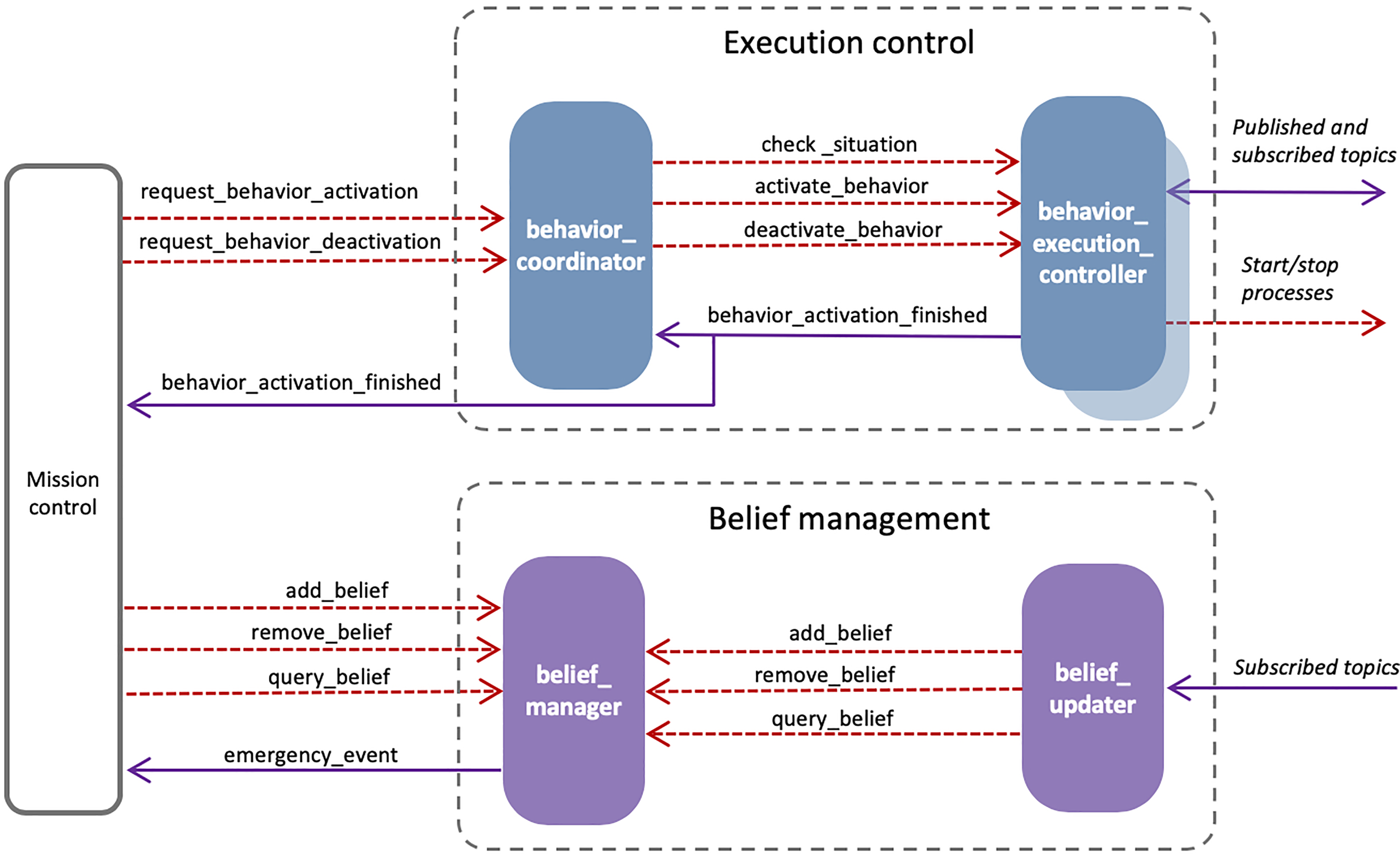
Detail of components related to execution control and belief management.
Each behavior execution controller is implemented as a separate ROS node that creates a uniform interface to be used by the behavior coordinator. The interface is defined with three request–reply services:
Check situation verifies that the behavior can be activated in the current situation of the environment (e.g. to activate the behavior take off the aerial robot must be landed).
Activate behavior activates the execution of the behavior using certain parameter values.
Deactivate behavior stops the behavior execution.
When a behavior is activated, the behavior execution controller monitors its execution in order to detect that it works as expected. For example, the execution of the behavior
The behavior coordinator works as a central process that handles the concurrent execution of active behaviors. This process responds to behavior activation requests and ensures the consistency of their execution. The behavior coordinator is implemented as a ROS node with two request–reply ROS services to activate and deactivate behaviors called respectively request behavior activation and request behavior deactivation. To accept a behavior activation request, the coordinator first checks the consistency between the behavior and the state of the environment. This is done by asking the behavior execution controller if the behavior satisfies the conditions of the situation (service check situation described above).
Then, the coordinator verifies that the behavior activation request is consistent with other active behaviors. This verification is done using a method that performs a search process to find a set of activations and deactivations that are consistent with the activation request. This is necessary because it may be possible that the activation of one behavior requires the activation or deactivation of other behaviors to satisfy the consistency constraints.
For this verification, the coordinator checks that a set of constraints between active behaviors are satisfied. These constraints are specific to the set of behaviors used in a particular robotic system and they are written by the developer (in a text file using YAML syntax). Constraints express relations about incompatibility and precedence. Figure 4 shows an example that illustrates how these relations are represented for the behavior

Example of constraints representing consistency relations between behaviors.
Since activations or deactivations can be asked by different requesters, the coordinator also uses a priority scheme to avoid conflicts. Each request includes a priority degree expressed with a number associated to each requester. For example, the current implementation of Aerostack uses the following priority degrees: 4 (emergency activation), 3 (manual activation), 2 (activation due to mission plan execution), and 1 (default activation). The activation by default corresponds to behaviors that must be active when there are no other incompatible behaviors active and the current situation is compatible with their activation. These behaviors may be, for example, behaviors that should be active when the robot is not doing any specific action. For instance, in the case of aerial robotics, the behavior
If the activation request is finally accepted, the coordinator performs the set of activations and deactivations using the services provided by behavior execution controllers. Requests to deactivate a behavior are analyzed in a similar way before being accepted because, when a behavior is deactivated, other behaviors can be activated (e.g. default behaviors). In addition, the coordinator is subscribed to the ROS topic behavior activation finished that informs when a behavior has finished its execution (e.g. because it has reached the goal or because it has failed). When this happens, the coordinator removes the behavior from the list of active behaviors and checks if other behaviors should be activated.
Behavior execution controllers are programmed for each particular control architecture. The developer writes specialized programs (e.g. with algorithms for feature extraction, SLAM, motion control, etc.) and, then, these programs are managed by a ROS node that implements the execution controller. Each execution controller is normally designed to be general in order to be reusable for more than one particular robot. For example, Aerostack provides a library of reusable behavior controllers that are common in aerial robotics.
To help developers program a behavior execution controller, Aerostack provides a C++ class called

C++ classes to program behavior execution controllers.
Specific functions of an execution controller.

ROS: Robot Operating System.
In order to improve the efficiency in the consumption of computational resources, we implement behavior execution controllers grouped in behavior systems. For this reason, we use a type of node provided by the ROS library called nodelet (http://wiki.ros.org/nodelet). Each behavior execution controller class is subclass of nodelet. Each nodelet implementing a behavior execution controller belongs to a group of nodelets that form a behavior system. For example, in the current implementation of Aerostack there is a behavior system, called basic_quadrotor_behaviors, that includes four behaviors:
Belief management
As explained above, the belief management system works as a working memory that stores dynamic data, needed for mission planning decision-making, that are generated during mission execution. The basic element stored in the memory is a belief which is represented using logic predicates in the general format of predicate(object, value) or in a simpler form property(object). Objects are represented with numerical identifiers as instances of a class. For example,
Aerostack uses a ROS node called belief manager to store and manage sets of beliefs (Figure 3). The belief manager provides the services add belief, remove belief, and query belief. The first two services are used to update the content of the memory of beliefs. The service query belief can be used to know if a belief is true and to determine the values of parameters. This is done using belief expressions that may include variables. For example, a query with the expression
The content of the belief memory can be updated using information from the functional layer (e.g. data related to feature extraction, self-localization, etc.). This is done by a specialized process called belief updater, implemented as a ROS node, that abstracts data from the behavior layer and updates a category of beliefs by changing the content of the belief memory. The current version of Aerostack provides a belief updater, that maintains updated a number of basic beliefs that are common for most aerial robots (e.g. beliefs related to the position, flight state, etc.). Developers must adapt this belief updater for each particular application if they need to add other specific beliefs.
The belief manager maintains consistency between beliefs according to their semantic properties. For example, in general, it is assumed that values are mutually exclusive. When a belief is added, for example,
This file can also include conditions to generate events that require urgent attention. For example, the following lines represent that when a predicate with the form
Mission control
The objective of the mission control system is to handle the execution of mission plans. Each mission plan is a program written by the developer that specifies the set of tasks that a robot has to perform in a particular mission. For mission control, the executive system in Aerostack uses two types of components that run concurrently (Figure 6): (1) a mission plan interpreter, which translates the mission plan into a sequence of execution requests following a goal-driven execution, and (2) a safety monitor that reacts in the presence of emergencies following an event-driven execution.

Detail of components for mission control.
The combination of both methods is handled by the behavior coordinator, which receives execution requests from both processes. The separation of the safety monitor from the mission plan interpreter is useful, for example, to simplify how mission plans are formulated because plans do not need to include tasks to cope with situations that are already handled by the safety monitor.
The current version of Aerostack provides two different mission plan interpreters to help developers specify mission plans. The first one is based on a Python Application Programming Interface (API). This is a convenient method for users who are familiar with computer programming languages and provides high flexibility for formulating plans with complex control regimes. The second interpreter uses a graphical approach based on behavior trees. This method is more appropriate for users who are less familiar with programming languages. This interpreter also provides better protection against errors and facilitates preemptive interaction between the user and the robot.
Mission plan specification using the Python API
Aerostack provides an API with a set of functions to activate/deactivate behaviors and functions to operate with the belief memory (see Table 2). With this method, the user can write the mission plan directly in Python calling specific functions of the API. Aerostack provides a ROS node to support this API called python-based mission interpreter.
Example functions of the Python API.

API: Application Programming Interface.
Figure 7 shows a simple example of a mission written in Python using the API provided by Aerostack. In this example, first, the function
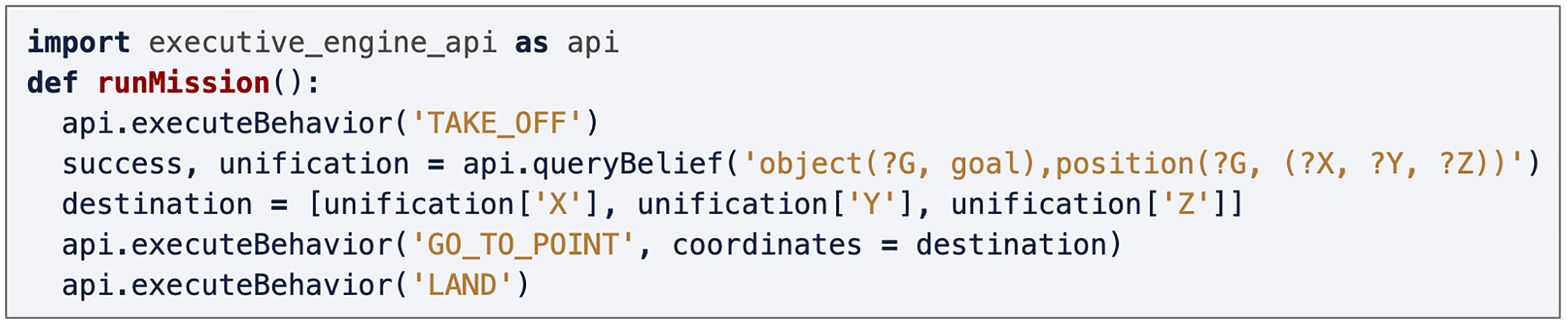
Simple example of a mission plan specified in Python.
Mission plan specification using behavior trees
A behavior tree is a visual modeling language that uses a graphical notation to represent the behavior of a system. In robotics, behavior trees have been used recently 20 and specifically for unmanned aerial vehicles (UAVs). 21,22 Aerostack provides two ROS nodes to operate with behavior trees: (1) an interpreter of behavior trees to execute the mission plan and monitor graphically its execution, and (2) a graphical editor to create the mission plan as a behavior tree. The graphical editor does not operate in runtime, but it is also implemented as a ROS node because it communicates with the behavior coordinator to get information about the available behaviors and the correct format of their parameters.
Each behavior tree is represented with a hierarchy of executable nodes. Nodes can succeed or fail during the execution of the mission plan. Intermediate nodes of the tree establish the control regime (e.g. a sequence, a loop, etc.). The types of intermediate nodes provided by Aerostack are similar to the nodes provided by common behavior trees:
Sequence. This node executes the child nodes in sequence and succeeds when all the children succeed. Otherwise it fails.
Selector. This node executes the child nodes in sequence and succeeds when one of the children succeeds. If none of them succeeds, it fails.
Parallel. This node executes its child nodes in parallel. Let N be the number of child nodes. It returns success if the number of succeeding children is larger or equal than a local constant S, specified by the user. Returns failure if the number of failing children is larger N−S.
Repeat. This node repeats the execution of a child node a number of times. Returns success. It can only have one child node.
Repeat until fail. This node repeats the sequential execution of child nodes until a child node fails. This node always succeeds.
Inverter. This node returns failure if the child node succeeds. Otherwise it succeeds.
Succeeder. This node executes its child node and, no matter what is the result of the execution, it always succeeds.
In Aerostack, leaf nodes of a behavior tree correspond to operations related to behaviors and beliefs in the following way:
Behavior operation node. A behavior operation node is used to activate or deactivate a behavior. There is a node that executes a behavior which succeeds when its goal is accomplished and fails if it is not possible (this is a usual node in general behavior trees). In Aerostack, there are also other operation nodes to control behaviors that are activated to operate concurrently: (1) a node that activates a behavior, which succeeds if the behavior is correctly activated (without waiting to reach a goal), and (2) a node that deactivates an active behavior, which succeeds if the behavior is correctly deactivated.
Belief operation node. A belief operation node interacts with the belief memory of Aerostack to add, remove, or query belief expressions. A node that adds a belief expression succeeds if the belief is correctly added. A node that removes a belief expression from the memory succeeds if the belief is correctly removed. A node that queries the memory is formulated with a belief expression with a set of predicates. This node succeeds if the belief expression matches the predicates that are present in the belief memory.
Behavior trees in Aerostack can use variables to communicate information between leaf nodes. For example, there can be a belief operation node in a mission plan to consult the coordinates of the current position of the robot. This node can use the following belief expression:
Figure 8 shows an example of behavior tree as it is displayed by the editor. Aerostack presents graphically the behavior tree using a hierarchy browser, which is an intuitive and compact graphical representation that we have found useful especially when the mission plan is complex. The editor uses standard edition mechanisms, which are familiar for general users, to create a behavior tree by adding, modifying, or deleting nodes of the tree. The editor provides guidance and assistance to users presenting valid options on menu bars and checking the presence of user errors in texts describing parameter values or belief expressions. The created behavior tree is stored in YAML file.

Example of behavior tree as it is displayed graphically by the editor.
To execute the behavior tree, the interpreter loads the YAML file with the mission plan and it follows its structure to generate a sequence of activations and deactivations of robot behaviors. During the execution, the interpreter shows a window that presents graphically the dynamic evolution of the execution and the current values of variables used by the behavior tree. The interpreter also facilitates preemptive interaction between the user and the robot, that is, the user can interrupt the mission at any point and continue the execution in another node of the behavior tree.
Experimental tests
This section describes the evaluation procedure that we conducted to analyze the effectiveness of the solution presented in this article. This evaluation was carried out by analyzing an aerial robotic system that was built using the software components presented in this article. The evaluation procedure pays attention to the trade-off between benefits for the final system and the costs related to development effort and performance efficiency.
Table 3 shows the quality characteristics analyzed in the evaluation procedure. To select these characteristics, we used the definitions used by the international standard ISO/IEC 25010:2011 (https://www.iso.org/obp/ui/#iso:std:iso-iec:25010:ed-1:v1:en), considering the following aspects: development effort (which was analyzed by observing the amount of code reused in relation to the amount of new code programmed), performance efficiency (time behavior and resource utilization), and benefits for the final system (user protection and fault tolerance). The following sections present the details and results of this evaluation procedure.
Quality characteristics analyzed in the evaluation procedure.

Development effort
This section describes the work that was done to evaluate how much Aerostack reduces the effort of building the executive system of a particular aerial robotic system. The system developed was based on the competition Autonomous Drone Race of IROS 2018 (International Conference of Intelligent Robots and Systems). This competition is a race with indoor autonomous flight challenges (e.g. frames to cross). In the experiments, we used a simplified version of this mission with four frames to cross (with different orientations and different heights). The aerial robot performs autonomously the mission, knowing in advance approximate locations of frames and using visual recognition to find the detailed position of frames before crossing them.
Figure 9 shows the area that we used for experimental flights with frames to cross. In these tests, we used an aerial vehicle Parrot Bebop 2, and a laptop computer with the following features: CPU Intel i7-7700HQ, 8 cores, 2.8 GHz, and 16 GB RAM. Figure 10 shows an example of a real flight. The figure also shows the sequence of the first five behaviors (

The aerial robot and the flight area used for experimental tests.

An example of the trajectory generated in a real flight.
For some experiments, we also performed simulated missions using a computer with the following features: CPU Intel i5-4460, 4 cores 3.2 GHz, and 16 GB RAM. Figure 11 shows a screen snapshot corresponding to the execution in one of the experiments using the Rotors simulator. 23 The image shows the behavior tree viewer on the left. On the right, the figure shows the 3D image generated by Rotors and, at the bottom, the image obtained by the front camera of the drone (showing with green color the frames recognized by the computer vision algorithm).
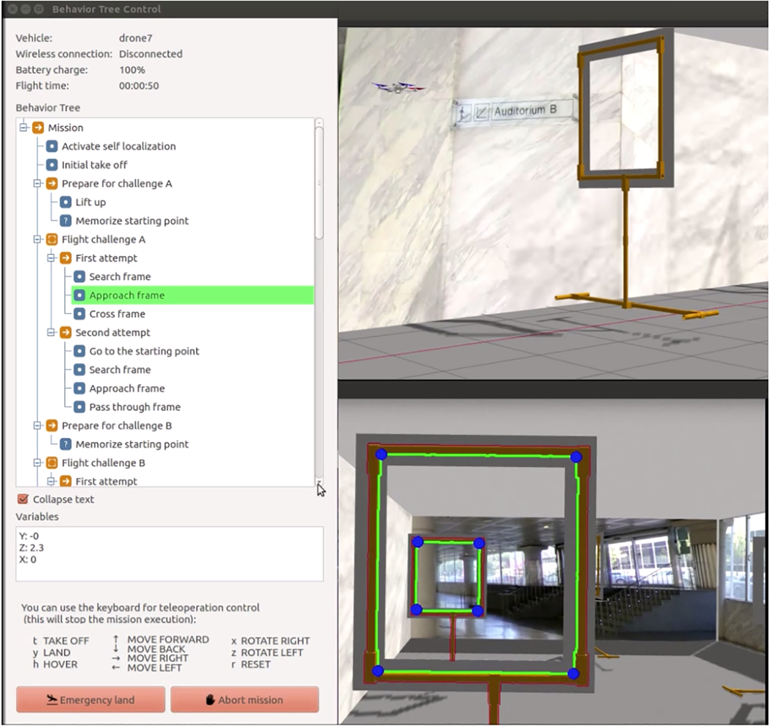
Screen snapshot corresponding to one of the experiments using the behavior tree interpreter (on the left) and the simulator Rotors (on the right).
The main tasks performed for building the executive system for this robotic system were the following:
Programming new execution controllers. We programmed several behavior execution controllers for the new motion behaviors used in this robot. This corresponds to the following behaviors (see Table 4):
Reusing software for execution control. Some of the execution controllers had been already programmed in previous projects, so they were available in Aerostack as reusable components. This corresponds to the following behaviors (see Table 4):
Configure common modules. This task corresponds to the configuration of the common ROS nodes corresponding of the executive system (e.g. behavior coordinator, mission plan interpreters, etc.). For example, the file of the behavior catalog was extended to include the new behaviors and the mission plan was written using both the Python API and the behavior tree editor to compare both approaches.
Motion behaviors used in the robotic system.

We evaluated reusability in this development, considering the degree to which Aerostack was used in building the executive system of the robotic system. The number of lines corresponding to the common components of Aerostack for executive systems is 13,519 lines, which includes: behavior tree interpreter, Python-based mission interpreter, behavior tree editor, behavior coordinator, belief manager, and class behavior process. Several behavior execution controllers were also reused (for behaviors
Computational cost of the executive system
The computational cost of the executive system developed with Aerostack was evaluated by measuring its performance efficiency in terms of time behavior and resource utilization. We estimated the processing time of the executive system in the following way. During the mission execution, a sequence of behavior activations is generated
Mission control time σ: arithmetic mean of
Coordination time τ: arithmetic mean of
Activation time φ: arithmetic mean of
Table 5 shows the results obtained for these variables. The experiments were done with a mission plan with n = 20. The mission plan was represented using two alternative options, the Python API and a behavior tree. The results show that the Python-based mission interpreter consumes more time than the behavior tree interpreter for mission control. For the behavior tree interpreter this value is
Results obtained in the experiments about processing time (values in ms).

Table 5 also presents the results corresponding to coordination time τ. As expected, values are similar for both the Python mission and the behavior tree mission. The values are τ = 1.8 ms for the behavior tree and τ = 1.1 ms for the Python mission.
Table 5 indicates that a significant part of the processing time corresponds to the activation time φ of behavior execution controllers, which has similar values with the behavior tree and with the Python mission (41.9 and 45.2 ms, respectively). This time depends on each particular application and it is affected by the number of ROS objects created for inter-process communication (e.g. subscribers, publishers, and service clients) and the number of processes that are started and stopped.
In general, the results show that the use of the general components of the executive system adds a delay estimated as σ + τ = 6.2 ms/behavior (using the behavior tree) and σ + τ = 53.2 ms/behavior (using Python). If we consider also the time used by the specific behavior execution controllers developed for this system the total delay is σ + τ + φ = 48.1 ms/behavior (using the behavior tree) and σ + τ + φ = 98.4 ms/behavior (using Python).
Concerning resource utilization, Table 6 shows CPU usage and memory usage of different processes related to the executive system. Regarding CPU usage, both the behavior tree and Python obtain similar values (12.1% and 11.8%). In the case of memory usage, the behavior tree obtains a lower value (43.7 MiB) than the value obtained by behavior trees (76 MiB) which is explained by the memory usage required by the process python2 (general interpreter of Python language). In general, these results are considered acceptable. The generic processes, in particular, obtain good values with measures for the behavior tree: CPU usage of 4.7% and memory usage of 18.7 MiB.
Results obtained in the experiments about resource utilization.

ROS: Robot Operating System.
Besides these measures, it is important to note that each ROS node consumes additional resources due to the use of node launchers (process roslaunch). According to our measures, the average use of each launcher consumes 47.8 MiB of memory and 0.3% of CPU usage. This consumption justifies using behavior systems that integrate groups of behavior execution controllers as nodelets, instead of separate ROS nodes. In our case, two behaviors systems (with four behaviors each system) use two launchers (which means 95.6 MiB and 0.6%), while using eight separate behaviors would use eight launchers (i.e. 382.4 MiB and 2.4%).
Usability and reliability of the final robotic system
This section describes the evaluation conducted to analyze the benefits that the final robotic system obtains by having the executive system developed using Aerostack. We considered here two characteristics: user error protection and fault tolerance. To assess user error protection, we manually constructed a testsite with a representative set of potential errors that users can make when they specify a mission plan. This testsite includes local errors (category A) related to simple lexical error (subcategory A.1) or syntax errors (subcategory A.2). This category also includes errors related to wrong values for parameters (subcategory A.3). We determined types of local errors by analyzing the representation used by the mission specification method. The testsite also includes other errors (category B) related to the global consistency of the mission (consistency between different tasks B.1 or consistency between tasks and the environment B.2). In this case, we identified types of errors by analyzing the interaction between robot behaviors and the interaction between robot behaviors and the environment. We created manually examples of these error types and were included in the testsite.
Table 7 shows a sample of tests corresponding to the testsite and how they are detected. The column detection time indicates when the error is detected: during specification time or in runtime. The column component indicates the main component of the executive system that is used to detect the error. All user errors corresponding to category A are detected during specification time using information provided by the behavior coordinator. These errors are detected during the construction of a mission plan using the behavior tree editor (the Phyton API does not provide protection for any of these errors during specification time).
Sample of tests performed to analyze user error protection.

During the execution of the mission, errors corresponding to category B are detected in the following way. Error 7 is not detected because it does not affect to the execution. Errors 8 and 10 are correctly detected and reported by the behavior coordinator. Error 11 is correctly detected and solved by the behavior coordinator deactivating the incompatible behavior. Errors 9 and 12 are correctly detected by behavior execution controllers (checking the conditions about the situation). In the case of error 13, the robot lands when the battery is discharged (this is a low-level safety mechanism independent of the executive system).
These tests show that the majority of these errors are detected and avoided with the help of the executive system, which provides an important protection against wrong and dangerous behaviors. However, it would be desirable that the executive system would detect all these errors when the operator specifies the plan, before the mission is executed.
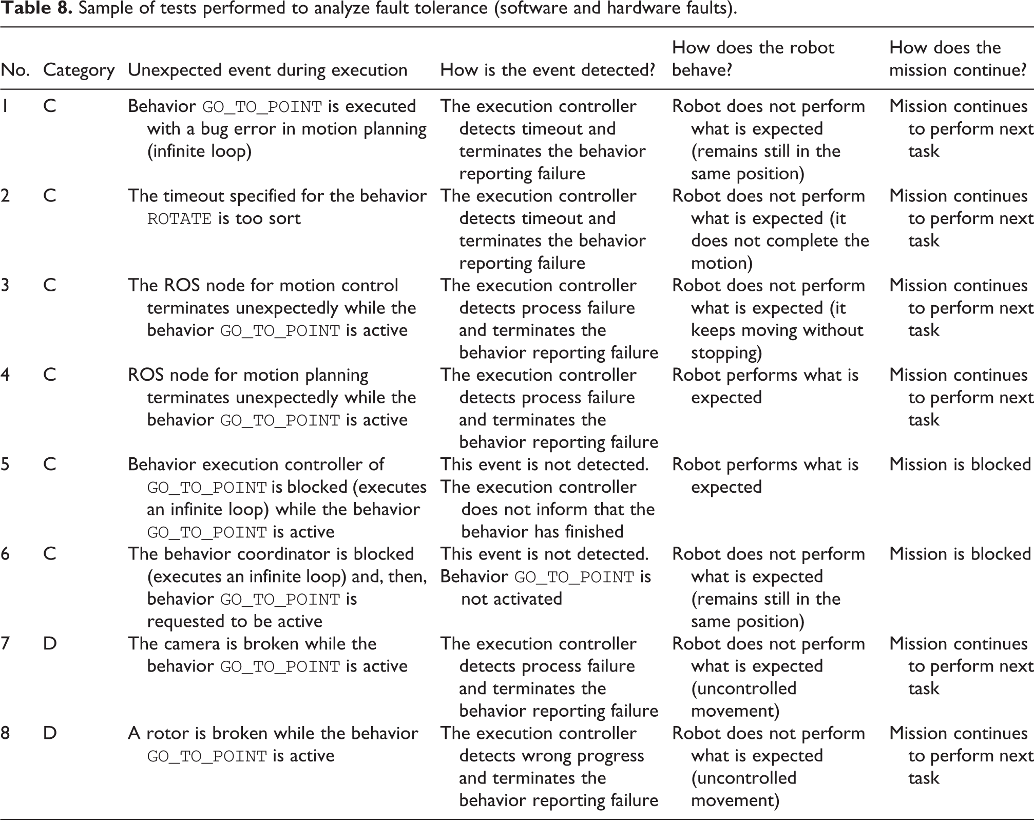
To assess fault tolerance, we constructed a testsite with a representative set of unexpected events. Tests are divided into the following categories: (C) software errors (D), hardware faults, and (E) interruptions caused by the operator or the safety monitor (e.g. caused by unexpected situations in the environment). Tables 8 and 9 show samples of tests corresponding to this testsite. In the majority of the cases, the execution of these tests show that the executive system is able to avoid a generalized failure, maintaining a limited functionality. Most of the problems are detected and the failure is correctly reported.
Sample of tests performed to analyze fault tolerance (software and hardware faults).
Sample of tests performed to analyze fault tolerance (interruptions).

Concerning events of category C, which are software errors that affect components of the control architecture, behavior execution controllers detect correctly events 1–4 and the mission continues normally to perform the next task. However, the response to events 5 and 6 is not satisfactory because the events are not detected and the mission execution is blocked. This is because these errors affect directly to the components of the executive system. In this case, an additional separate solution should be used to monitor and verify the correct the execution of the executive system.
Events of category D (hardware faults) are correctly detected by behavior execution controllers (events 7 and 8). However, hardware faults that require a rapid reaction (e.g. event 8) should be managed by lower level processes operating at high frequencies to avoid or mitigate dangerous effects of uncontrolled behaviors.
Events of category E (interruptions) are also correctly managed by the behavior coordinator (events 9–14) to avoid the execution of incompatible behaviors. The behavior tree interpreter was used here (event number 10) to stop and continue the mission execution in a different point (the Python-based mission interpreter does not provide this functionality).
Interpretation of evaluation results
The evaluation results show the costs and benefits of using Aerostack for building the executive system of an aerial robotic system. The main conclusions of this evaluation can be summarized as follows:
A large amount of Aerostack code was reused compared to the new code programmed. The size of the code reused to develop the executive system of an aerial robot was 15,434 lines and the size of the new code programmed was 2839 lines, which is a high percentage of code reused (84%).
The performance efficiency of the methods provided by Aerostack for mission plan execution was acceptable in aerial missions. The use of the executive system generates an average delay of 48.1 ms/behavior (using the behavior tree interpreter) and 98.4 ms/behavior (using the Python-based mission interpreter). In missions that activate behaviors at low frequencies (less than 0.2 Hz, as it happens in missions used in our experiments) we consider that a delay of less than 100 ms/behavior is admissible, since it would increase the total time to complete the mission in less than 1% (in the case of a Python mission, this increase is around 2%). This is particularly acceptable in missions where time is not critical and high degrees of usability and reliability are required (e.g. inventory missions, inspection missions, etc.).
The processing times of methods provided by Aerostack for mission plan specification are different. The processing time for executing missions plans is different for the behavior tree interpreter and the Python-based mission interpreter. The time spent is 4.4 ms/behavior using the behavior tree and 54.8 ms/behavior using Python. As it was mentioned, this difference may be explained by the fact that Python missions use the general interpreter of the Python language, which requires additional computation (the behavior tree interpreter is programmed in C++).
The behavior tree editor increases user error protection during specification time. The behavior tree editor is able to avoid user errors corresponding to syntax errors and certain semantic errors (wrong names and wrong types of values) during specification time, using information provided by the behavior coordinator. In contrast, the Python-based mission interpreter does not detect the presence of these errors before the mission is executed.
The executive system increases user error protection about errors related to global consistency during execution time. User errors related to global consistency are detected by the executive system during the mission execution, which is useful to improve usability and avoid dangerous behaviors. However, in order to avoid starting the execution of mission plans that have specification errors, these errors should be detected in advance, when the developer specifies the plan.
The executive system increases fault tolerance. The executive system detects the presence of problems produced by unexpected events (e.g. software errors, hardware faults, and interruptions) and continues the normal execution of the mission. However, there are certain kind of events (e.g. some hardware faults or software errors that affect directly the executive system) that need additional mechanisms for fault tolerance.
The executive system facilitates preemptive interaction between the user and robot. Interruptions are correctly managed by the system with the help of the behavior coordinator and mission plan interpreters. The behavior tree interpreter is more flexible than the Python-based mission interpreter because the user can stop and continue the mission execution in a different point of the behavior tree. This functionality is not provided by the Python-based mission interpreter.
Related work
This section analyzes the similarities and differences of the solution described in this article with existing tools. The analysis has focused mainly on available open-source tools. One of the distinctive characteristics of the tool described in this article is the way it separates the execution control of a mission plan into simpler processes that run concurrently. For example, the mission plan interpreter is executed separately from the safety monitor and the combination of both methods is handled by a behavior coordination process that also accepts operator interruptions.
Part of the functionality provided by our coordination method is similar to the functionality of Request and Resource Checker (R2C) 24 based on the LAAS architecture. 17 Both methods verify execution requests before they are accepted, which is useful to facilitate reliability. However, R2C does not manage multiple execution requesters and it uses a different verification algorithm. Besides, we have not found its implementation in an open-source software tool that is available for developers.
To translate a mission plan into low-level commands, a usual approach followed by the executive system is to have a uniform interface to operate with the multiple robot functions necessary for autonomous behavior (e.g. feature extraction, SLAM, motion control, etc.). The way this uniform interface is implemented varies in different software tools.
For example, FlexBE 5 uses the concept of state and implements the uniform interface as a state with a life cycle (http://wiki.ros.org/flexbe/Tutorials/The%20State%20Lifecycle) using a Python class (called EventState) with common functions. The software toolbox CRAM 8 uses process modules implemented as Lisp programs that encapsulate functions executing ROS nodes. The tool ROSPlan 7 uses actions that are implemented with the help of a C++ class (called RPActionInterfaceClass). The software tool Genom 25 uses modules that are generated automatically (in language C) for control architectures based on the LAAS architecture.
In contrast to these tools, our method uses the notion of behavior that has been commonly used in behavior-based systems in robotics 26,27 and as a basic concept for specifying mission plans. 28,29 In our case, a mission plan is expressed with operations that activate and deactivate behaviors. The uniform interface is implemented with a behavior execution controller which is similar to other solutions to manage the life cycle execution of a process. For example, ROS 2 uses managed nodes (https://design.ros2.org/articles/node_lifecycle.html), that is, nodes with a managed life cycle and FlexBE uses a similar idea although it is applied to the concept of state. The main difference with these solutions is that a behavior execution controller is specialized in the execution of a behavior, instead of a general process or a general state, and includes specialized functions to verify its correct execution.
Our mission plans can also use operations to access a belief memory that stores relevant facts generated during the execution. The belief management system has been designed to work as a working memory, paying attention to the efficiency in consumption of computational resources, as required in aerial robotics. Therefore, it does not include complex reasoning capabilities related to logic representation (e.g. automated deduction) that are provided by other approaches in robotics such as KnowRob. 30
Concerning the representation language used to specify mission plans, software tools use different methods. For instance, there are tools that formulate mission plans using representations based on finite state machines such as SMACH, 2 rFSM, 3 RAFCON, 4 and FlexBE. 5 Some tools use behavior trees such as the ROS behavior_tree package 6 and BehaviorTree.CPP (MOOD2Be Project). The previous version of Aerostack (version 2.0) included a task-based approach to represent mission plans represented using the TML language. 31 An imperative language like Python is used by PyRobots 32 to formulate mission plans.
In the method presented in this article, mission plans can be formulated as a Python program using a Python API that provides functions to activate/deactivate behaviors and access the belief memory. The mission plan can also be formulated using a C++ program using ROS services. Alternatively, the mission plan can be specified as a behavior tree. Our behavior tree representation is similar to the representation used by other tools although, as a main difference, our method is integrated with the executive system, so that it can perform queries to a belief memory (using variables that communicate information between tree nodes) and it includes operations to activate and deactivate behaviors that operate concurrently.
The method presented in this document assumes that the mission plan is provided as input, that is, the mission plan is either specified by a human developer or generated by an external automated planner, not included in our model of executive system. For this reason, our work has paid attention to include protection methods against specification errors. Other software tools use automated reasoners and symbolic languages that are useful to generate mission plans. For example, CRAM 8 uses Lisp language and, among other components, includes an automated reasoner based on Prolog. ROSPlan 7 uses PDDL language and an automated planner to generate mission plans.
Conclusions
This article has presented results of recent advances in the Aerostack software framework to address issues related to safety and efficiency, which may be critical in the case of aerial robots. The article has described a solution to help developers build the executive system of an autonomous robot. The solution is presented as a model of executive system formulated as a general software architecture and a set of reusable open-source components that perform executive functions. The architecture uses an original design that divides the execution control of a mission plan into different processes with separate functions (plan interpretation, safety monitoring, behavior coordination, belief management, etc.). This model is now part of the Aerostack it is publicly available as open-source software.
The article presents the evaluation of the solution with an aerial robotic system analyzing the trade-off between benefits (about usability and reliability) and costs (about development effort and performance efficiency). As it is shown by the results, our solution improves the final robotic system in terms of better user error protection and fault tolerance. The evaluation shows that these benefits are obtained with acceptable development effort and computational cost.
The evaluation also shows that there are issues related to usability and reliability that are not fully covered by our solution. For example, our method detects critical errors about global consistency during the mission execution, but it would be better to detect these errors in advance, when the developer specifies the plan. Part of our future research work is oriented to give an answer to this issue by representing explicitly semantic properties of mission plans that are used by automatic validation methods, considering also the practical costs of its use.
Another issue that is not covered by the solution presented in this article is a protection mechanism against errors that affect directly the executive system. In this case, additional protection methods should be considered. For example, a possible solution would be to add a new functionality to the behavior coordinator (which is a stable component with low probability of failure) to supervise the execution of the behavior execution controllers (which have higher probability of failure since they are dependent on the final application).
Footnotes
Declaration of conflicting interests
The author(s) declared no potential conflicts of interest with respect to the research, authorship, and/or publication of this article.
Funding
The author(s) disclosed receipt of the following financial support for the research, authorship, and/or publication of this article: Part of the work presented in this article has been developed as a project supported by the European Union’s Horizon 2020 Research and Innovation Program under the Project ROSIN (no. 732287). This work has also received funding from the Spanish Ministry of Science, Innovation and Universities through the project RTI2018-100847-B-C21.