
Abstract
In this article, a novel real-time artificial neural network–based adaptable switching dynamic controller is developed and practically implemented. It will be used for real-time control of two-wheeled balance robot which can balance itself upright position on different surfaces. In order to examine the efficiency of the proposed controller, a two-wheeled mobile balance robot is designed and a test platform for experimental setup is made for balance problem on different surfaces. In a developed adaptive controller algorithm which is capable to adapt different surfaces, mean absolute target angle deviation error, mean absolute target displacement deviation error and mean absolute controller output data are employed for surface estimation by using artificial neural network. In a designed two-wheeled mobile balance robot system, robot tilt angle is estimated via Kalman filter from accelerometer and gyroscope sensor signals. Furthermore, a visual robot control interface is developed in C++ software development environment so that robot controller parameters can be changed as desired. In addition, robot balance angle, linear displacement and controller output can be observed online on personal computer. According to the real-time experimental results, the proposed novel type controller gives more effective results than the classic ones.
Keywords
Introduction
The studies in the field of robotics have enormously advanced and improved nowadays. In parallel with this improvement, robots make our lives easy in many fields like industry, health, society, and so on. 1 The capabilities of many robots, used actively now, have advanced considerably. The more they advance, the more they need for energy. For that reason, in the last decade, many researchers have studied two-wheeled balance robots which need less energy and have a very good manoeuvrability instead of four-wheeled robots. 2,3 Many researchers worldwide have made research about various types of explorative two-wheeled mobile balance (TWMBR) which balances itself, moves backward and forward turns right and left. 4,5 Many of these studies published are based upon simulation results and theoretical analysis. Because of their non-linear structure, that kind of system dynamics are rather complex and their motion planning is very hard. 6 However, many researchers have built real-time TWMBR systems and implemented their own control algorithms on those robot systems. For example, they have developed a robot called JOE in Industrial Electronic Laboratory in Sweden Federal Technology Institute. 7 Kuindersma et al. working for Perceptual Robotic Laboratories have studied a humanoid U Bot-5. 8 National Aeronautics and Space Administration’s (NASA’s) Robonaut, another two-wheeled robot, has been made by Defense Advanced Research Projects Agency (DARPA) with the cooperation of NASA. 9 Cardea, developed by Massachusetts Institute of Technology, is another sample of TWMBR. 10 The two-wheeled vehicle called B2 has been designed as an alternative automatic commercial transportation system. 11 Numerous controller structures are created for the control and balance of TWMBR systems such as classical control, 12 proportional integral-velocity control, 13 Fuzzy logic-based control, 14 neural network control, 3 sliding mode control 4 and adaptive control. 15
As seen in the literature studies above, most of the studies about TWMBR have been made on flat and firm grounds. In addition, Kim and Lee have developed a magnet-wheeled mobile robot moving on curved surfaces. 16 Qiao et al. have proposed wheel-legged robot with a front module, a rear module and an active waist joint in order to make the robot pass through the curved narrow channel. 17
In this article, balance performance of the robot is observed on loose surface such as sand, pebble and soil. Besides, artificial neural network (ANN)-based real-time switching dynamic controller, which is applied on the robot to solve balance problem on such surfaces, is a novel structure.
This article is organized as follows: The second section describes structure of the TWMBR, the mobile robot hardware components and the robot control interface on personal computer (PC). The third section gives the mathematical analysis for developed TWMBR system. The fourth section describes dynamic surface estimator on the control system and controller mechanism of the robot system. The fifth section presents experimental results of the balance robot, and the last section gives the study results.
Structure of the TWMBR and the robot control hardware
For TWMBR’s mechanical design, an appropriate equilibrium point must be tuned in order to control the robot because of its non-linear structure. The hardware of the robot was built regarding all the requirements. As shown in Figure 1(a) and (b), the developed TWMBR has three layers which make it lighter and has a good centre of gravity. At the bottom layer, there are two identical permanent magnet DC motors coupled to a gearbox for each wheel and with an integrated encoder. There is also micro-electro-mechanical systems (MEMS)-based inertia measurement unit sensor which contains gyroscope and accelerometer together. Cortex M3 microprocessor–based development board which controls all units of the robot system and provides data communication by using Bluetooth wireless unit. In the middle layer, there is a DC motor driver circuit which can control two identical DC motors moving independently at the robot system. At the top layer, there is a lithium polymer battery supplying energy for the whole system. Figure 1(c) shows the side view and top view of TWMBR on coordinate system for mathematical analysis.

The structure of TWMBR: (a) front view, (b) top view, (c) side view and top view of TWMBR on the coordinate system. TWMBR: two-wheeled mobile balance robot.
The general block diagram given in Figure 2(a) shows the detailed hardware component of the developed TWMBR control system. As shown in Figure 2(a), sensor data are taken for the robot control on I2C data line by Cortex M3 microprocessor. Furthermore, left and right encoder data are taken on timer 1 and timer 2 input ports. The robot control interface was designed in Visual C++ software development environment for online control of TWMBR remotely, for online change of all robot control parameters and to observe and make sense of robot’s reaction to different surfaces diagrammatically on PC by using the wireless communication unit. Mathematical basis of parameter adaptation algorithm was built with these online data and performed real-time through the codes of Cortex M3 microprocessor. Many real-time experiments were done to enable robot’s stable balance on various surfaces by means of the designed user interface.

(a) The general block diagram of TWMBR control hardware; (b) robot balance test platform. TWMBR: two-wheeled mobile balance robot.
On the designed TWMBR control system, MEMS-based sensor groups were used, which include three-axis gyroscope sensors and three-axis accelerometer sensors. The information how we achieved sensor fusion and sensor calibration for TWMBR is given in detail in the work by Guner et al. 18 Additionally, designed robot balance test platform is 70 cm × 210 cm × 4 cm of sizes. It was divided into three parts and each part was filled with soil, pebble and sand as shown in Figure 2(b).
Mathematical model of TWMBR system
Mathematical dynamic modelling of TWMBR is rather important in terms of stability analysis and system simulation. It is also very important that control algorithms are created according to these model parameters. Many researchers generally studying in the field of TWMBR obtain the robot’s non-linear dynamic model by utilizing the equations such as Lagrange-Euler or Newton-Euler. In this article, TWMBR system is modelled based on Lagrange-Euler equations referred as Yamamoto. 19 Figure 1(c) shows coordinate system of side and top views of TWMBR. In Figure 1(c), xb, yb, zb denote the system’s centre of gravity, xm, ym, zm denote the robot wheel’s centre of gravity and θl, r defines left and right wheel angle on the coordinate system. It is necessary to specify the robot’s physical parameters very well to get the TWMBR’s equation of motion properly. Physical parameters of the applied balance robot are given in Table 1.
Physical parameters of TWMBR.

TWMBR: two-wheeled mobile balance robot; Electromotive Force: EMF.
Considering the coordinate system in Figure 1(c) and physical parameters of balance robot in Table 1, TWMBR’s equations of motion were derived by using Lagrange method. If TWMBR’s front becomes positive x-axis and t = 0, balance equation for each coordinate will be as given below

where the robot’s right and left wheels mean angle is defined by θ and body yaw angle by ∅. As shown in Figure 1(c), shaft centre to which wheels are integrated (xm, ym, zm), the position of left wheel (xl, yl, zl) and right wheel (xr, yr, zr) on the coordinate system and robot’s bodyweight centre (xb, yb, zb) are expressed in equations (2) to (5), respectively


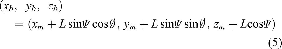
where Ψ denotes body tilt angle. The robot’s energy equations can be defines as


where T1 denotes translational kinetic energy, T2 denotes rotational kinetic energy and U defines potential energy. Using kinetic energy equations, Lagrange function L has the following expression

Using the Lagrange function, force components of θ, Ψ, ∅ and for linearizing process in the equilibrium point of TWMBR, we consider the Ψ ≅ 0 (sinΨ ≅ Ψ, cosΨ ≅ 1) and neglect the second order term like


Considering DC motor torque and viscose friction, generalized forces are represented as in the following equations


where il, r denotes left and right motor current and vl, r denotes left and right motor voltage. In the study, we will evaluate DC motor equation utilizing the relation between il, r current and vl, r voltage. If we neglect the frictions inside the motor (Bm) and motor inductance (Lm), the DC motor current will be as in equation (17)

Using equation (17), the generalized forces are expressed as follows


where
As shown in the equations of motion above, the motion dynamic of the system depends on surface structure. In this study, it is shown with real-time application results that controller parameters change on loose surfaces. State space expressions of TWMBR, developed according to sytem parameters, are presented in “Experimental results” section.
Design of adaptive dynamic controller for different surfaces
It is rather hard for balance robot system to keep its balance on two wheels and on all surfaces robustly and presents the desired behaviour. It is necessary to design a dynamic controller so that we can overcome the robot’s adaptation problem on different surfaces shown in Figure 2(b), and the system behaviour can be more stable on all various grounds. In this study, TWMBR is able to sense the surface autonomously by means of the proposed novel algorithm. Thus, it can update the optimal controller parameters according to surface by virtue of ANN-based adaptive controller. The proposed ANN-based adaptive switching controller structure is given in Figure 3.

TWMBR’s block diagram of adaptive control with switching. TWMBR: two-wheeled mobile balance robot.
As shown in Figure 3, the system consists of multi-controller, ANN-based adaptation mechanism and sensor fusion blocks. In this figure, ΨTarget expresses target tilt angle and XTarget is target linear displacement. And also, XWheel is wheel displacement calculated as Rθ.

where uσ(t) denotes control signal for different surfaces and e(t) defines control error (ΨTarget − Ψ). Fine tuning of the controller parameters is found by trial-and-error via robot control interface. The most sensitive PID parameters for soil, pebble and sand floor are specified for this goal as given in Figure 3.
ANN-based adaptation mechanism
In the study, the robot’s real-time balance experiments are done on three different floors which have soil, pebble and sand on it. During these experiments, actions of the robot are analysed considering data such as tilt angle Ψ(t), linear displacement of robot X(t) and plant input uσ(t) for three different surfaces. The action of the robot on each floor (soil, pebble and sand) is analysed one by one referring to the PID controller test parameter such as
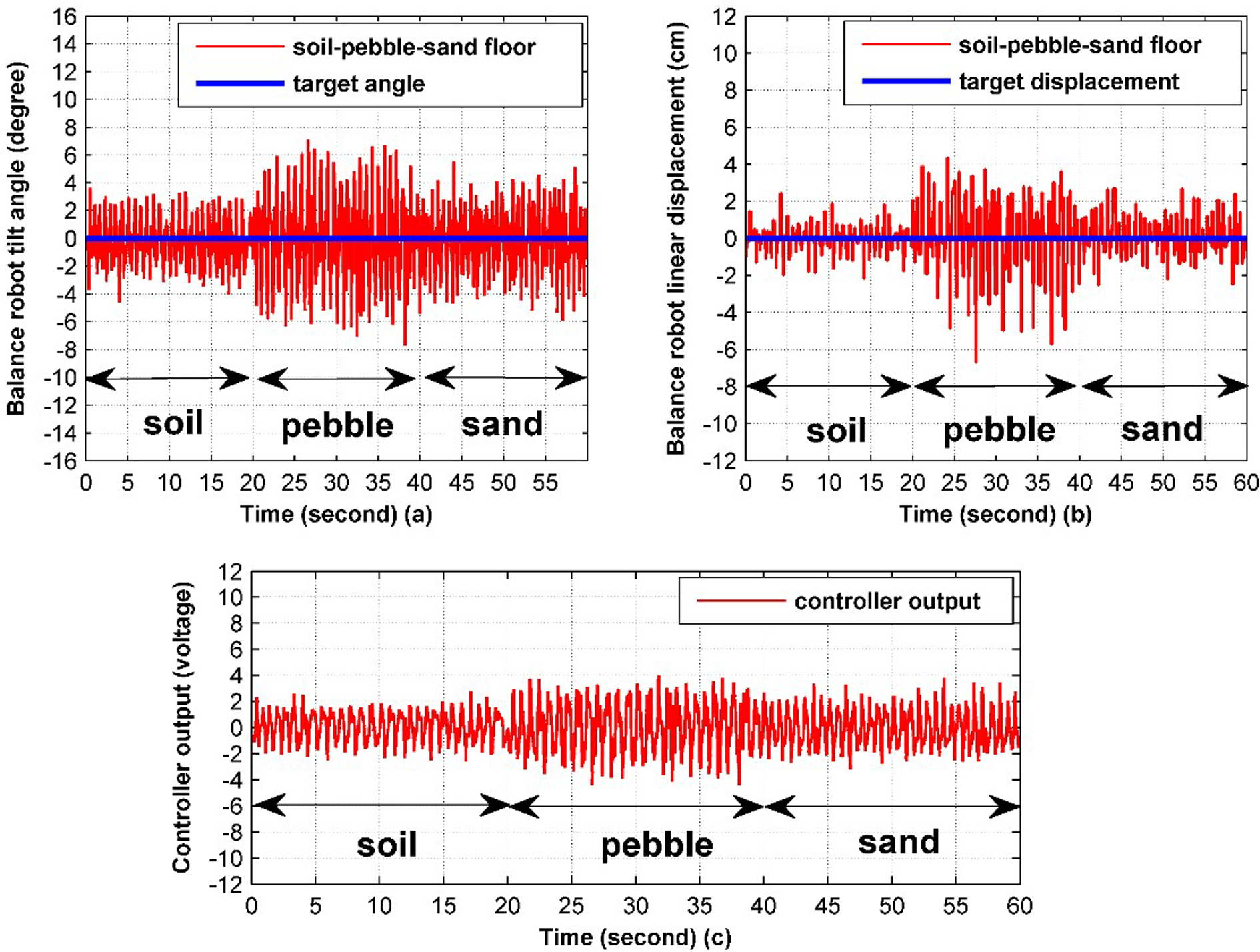
Change in (a) tilt angle, (b) linear displacement, (c) controller output on three floors.
The robot’s centre of gravity is 0° as a result of experimental tests. Therefore, it was chosen as ΨTarget = 0°. In this article, to overcome this problem, an ANN-based adaptation mechanism was designed. For the designed parameter adaptation mechanism, the balance state of the robot on each floor was observed with the same controller parameter for 2 min without having any external factor, and for each floor, 12,000 data were obtained totally. Because that the robot system actions are time-variable and non-linear, the data are re-evaluated with the method of systematic sampling (N = 600). The equations about mean absolute target angle deviation error (MATADE), mean absolute target displacement deviation error (MATDDE) and mean absolute controller output (MACO) are given in equations (22–24), respectively


Hence, we have 20 meaningful data about the robot for each floor in a controller test parameter. In Figure 5(a), the 20 data (MATADE, MATDDE and MACO) used in the structure of ANN surface classifier are shown.
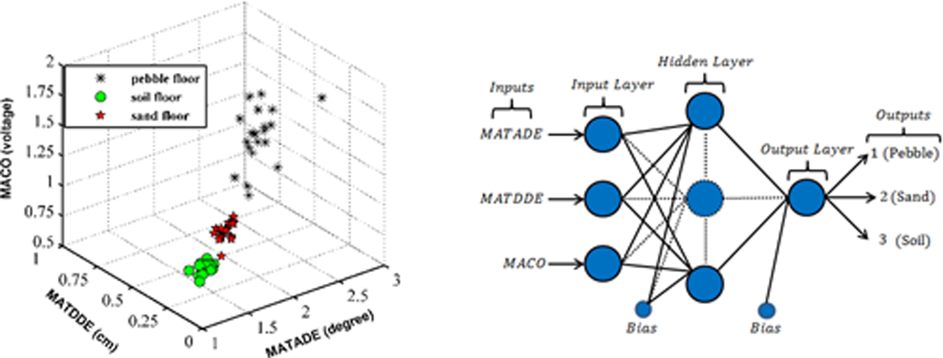
(a) MATADE-MATDDE-MACO data on three floor; (b) ANN model of TWMBR control system. MATADE: mean absolute target angle deviation error ; -MATDDE: mean absolute target displacement deviation error; MACO: mean absolute controller output; ANN: artificial neural network; TWMBR: two-wheeled mobile balance robot.
These data are classified with ANN in order to define the floor on which the robot stands. After surface classification, the prediction of the floor is made by parameter adaptation mechanism. The model of ANN structure used for this study is shown in Figure 5(b).
That ANN model is capable of evaluating input data of the robot and defining its ground. Also, three output signals (σ = 1, 2, 3) making controller choice for three surfaces (pebble is 1, sand is 2 and soil is 3) are obtained. In the study, it is chosen that hidden neuron number (HNN) as 4, 5, 6, 7, 8, 9, 10, learning rate (LR) as 0.2, 0.4, 0.6, 0.8, 1.0, 1.2 values, feature number as 3, target stopping criteria as 0.001 accuracy value or 1000 iteration number and the momentum constant as 0.9 to determine the appropriate ANN structure. Also, three different activation functions (logarithmic sigmoid, tangent sigmoid, purelin) are used for neurons on hidden layer and output layer in each experiment. That ANN structure has a feed-forward and multilayer network trained with back propagation algorithm. The best performance value for ANN model has been obtained using LR = 0.2, HNN = 8 in purelin activation function. The table of some of ANN structure used for this study is shown in Table 2.
ANN system output performance for HNN is 8.

ANN: artificial neural network; HNN: hidden neuron number; FN: feature number; LR: learning rate.
A real-time ANN algorithm is made and applied on the robot real-time considering the weight bias and activation function of this network structure and by applying the optimum controller parameter on the robot it is achieved that the robot can keep its balance more stably.
Experimental results
In this section, we will implement the TWMBR by using the effective controller based on the proposed ANN-based adaptive switching controller. Moreover, in the experimental test, we assume the robot physical parameters as given in Table 3.
Physical parameters of TWMBR.

TWMBR: two-wheeled mobile balance robot.
Equation (25) shows the state space expression obtained from TWMBR physical parameters in Table 3 using mathematical model equations (10) to (20)

The controller parameters on different surfaces are found roughly with simulation results by utilizing the mathematical model of the robot system. Then, controller parameters are obtained by fine tuning via real-time robot control interface. The controller parameters given in Figure 3 were obtained as a result of real-time tests of the robot for three surfaces as soil (σ = 1), pebble (σ = 2) and sand (σ = 3). For this controller, the robot’s tilt angle, the distance it takes, and plant input uσ(t) change in terms of time are observed as shown in Figure 6, three floors for 20 s without any external factor.

Change in (a) tilt angle, (b) linear displacement and (c) controller output on three floors.
When Figure 6 is compared with the ones obtained with just one controller Figure 4, it is seen that the system keeps balance much better on different surfaces. Obtained balance performance values are shown in Table 4.
TWMBR performance evalution.

TWMBR: two-wheeled mobile balance robot; ANN: artificial neural network.
However, parameters in Figures 4 and 6 change rapidly because the surfaces are loose. As seen in Figure 7, surface deformation affects desired balance of the robot very much.

Surface deformation of (a) soil, (b) pebble and (c) sand floor.
Conclusions
Many researchers have studied about two-wheeled balance robots. However, almost all of the researches have focused on the solution of the balance problem on just one kind of surface. In this study, a new controller structure was created by analysing the balance problem of the robot on different surfaces. First of all, the angle oscillation, the distance it takes forward and backward and controller output changes at the same time when the robot tries to keep balance were classified with ANN and surface estimation was achieved. At the end of ANN-based classification process, the controller parameter of the robot was changed on the robot with respect to surface by using the adaptation mechanism. The proposed adaptive control structure with switching was applied real-time on TWMBR for different surfaces. These real-time experimental results show that the proposed controller structure had a positive contribution to the robot behaviour on different grounds, because the angle oscillation and distance it takes forward and backward were decreased. At the same time, the controller output change was considerably limited, thus, the energy efficiency was increased. It is seen that TWMBR system becomes more robust and stable.
Footnotes
Declaration of conflicting interests
The author(s) declared no potential conflicts of interest with respect to the research, authorship, and/or publication of this article.
Funding
The author(s) received no financial support for the research, authorship, and/or publication of this article.