
Abstract
A grasp planning method based on the volume and flattening of a generalized force ellipsoid is proposed to improve the grasping ability of a dexterous robotic hand. First, according to the general solution of joint torques for a dexterous robotic hand, a grasping indicator for the dexterous hand—the maximum volume of a generalized external force ellipsoid and the minimum volume of a generalized contact internal force ellipsoid during accepted flattening—is proposed. Second, an optimal grasp planning method based on a task is established using the grasping indicator as an objective function. Finally, a simulation analysis and grasping experiment are performed. Results show that when the grasping experiment is conducted with the grasping configuration and positions of contact points optimized using the proposed grasping indicator, the root-mean-square values of the joint torques and contact internal forces of the dexterous hand are at a minimum. The effectiveness of the proposed grasping planning method is thus demonstrated.
Keywords
Introduction
The basic task of a dexterous hand is to grasp an object stably. The stability of multifingered grasping is generally characterized by force-closure performance under which the contact forces applied by the fingers can balance arbitrary forces and torques exerted on the object. The target of grasp planning is to find the optimal grasping configuration and positions of contact points. Grasp planning can be classified into grasp planning based on the human hand and grasp planning based on optimization.
Grasp planning based on the human hand
Hong and Tan 1 studied the motion capture of the human hand with the Virtual Programming Language (VPL) data glove and teleoperated the Utah/MIT dexterous hand. Rohling and Hollerbach 2 captured the positions of fingertips with the SARCOS manipulator and teleoperated the Utah/MIT dexterous hand. Kang and Ikeuchi 3 investigated the motion capture of the human hand with a combination of stereo vision and a data glove. However, the capture accuracy and real-time performance are limited when using the motion capture based on data gloves, tactile sensors, and stereo vision. Liu and Zhang 4 developed a joint space mapping method based on virtual joints and virtual fingers and intuitively verified the mapping in the virtual environment. Fischer et al. 5 established a relationship between the joint space of the human hand and the Cartesian space of the fingertips with a neural net algorithm, and mapped motion from the human hand to the dexterous hand in the workspace, and finally planned the grasping for the Deutsches Zentrum für Luft-und Raumfahrt e.V. (DLR) hand. Liu et al. 6 proposed a fingertip mapping method in Cartesian space based on virtual fingers. However, the accuracy of motion mapping can be affected by structural differences between the human hand and dexterous hand. Aleotti and Caselli 7,8 proposed a virtual reality-based Programming by Demonstration system for investigating the grasp recognition in virtual reality and presented a grasp planning algorithm and a grasp synthesis strategy by demonstration. To avoid the difficult 3-D reconstruction and parametric grasp classification, Romero et al. 9,10 presented a human-to-robot grasp mapping system in which the human hand posture was classified according to a single image and the classified posture was mapped to a specific robot hand. However, it is only suitable for volar grasping with tactile feedback and not for the pinch grasp and precision disk grasp owing to visual errors. All of the issues mentioned limit the practical application of grasp planning based on the human hand.
Grasp planning based on optimization
Nakamura et al. 11 used the minimum contact internal forces as the grasping indicator and developed a grasp planning under the condition that force-closure constraints and static frictional constraints are satisfied. Markenscoff et al. 12 took the minimum sum of the force/moment applied to the object as a grasping indicator and planned the grasping of polyhedral objects. Zhang et al. 13 and Li et al. 14 introduced the maximum joint motion isotropy as a grasping indicator and accomplished a grasp planning for three-fingered hand with symmetrical configuration. Ding et al. 15 took the minimum distance between the center of mass of the grasped object and the center of the contact points as a grasping indicator, and planned grasping from the known contact points to the remaining contact points using a nonlinear optimal algorithm. Mo and coworkers 16,17 used the maximum external wrench as a criterion to evaluate the performances of the planning. The grasping indicators mentioned only guarantee the maximum grasping efficiency without describing detailed force mapping relations among the joint torque space, contact force space, and external object force. Li and Sastry 18 and Xiong et al. 19 took the singular value product of the grasping matrix as a grasping indicator to measure the grasping stability and planned the contact points. Singh and Ambike 20 used the minimum singular value of the grasping matrix and the norm of the contact internal force as grasping indicators and planned the contact points and grasping forces. Bicchi and Sorrentino 21 introduced the efficiency index, the ratio of the norm of fingertip output velocity to the norm of the joint input velocity, as a grasping indicator in optimizing the grasping configuration. Guo and Sun 22 took the position grade and relative loading capability in the joint space as a grasping indicator in optimizing the grasping configuration. Among the above grasp planning indicators, some consider only the optimization of contact positions without considering the optimization of the grasping configuration, and some consider only the external forces while ignoring the internal forces. Yang and Zhang 23 introduced the concept of the generalized internal force ellipsoid and took the shortest axis of the generalized external force ellipsoid and the longest axis of the generalized internal force ellipsoid as a grasping indicator to accomplish the grasp planning. However, the indicator above cannot reflect the volume and flattening of the generalized external force ellipsoid and the generalized contact internal force ellipsoid simultaneously.
The present article first gives the general solution of joint torques. The generalized external/internal force ellipsoid is then defined, and the volume and flattening of the generalized force ellipsoid are given to reflect the shape and size of the ellipsoid. The article then proposes a new grasping indicator—the maximum volume of a generalized external force ellipsoid and the minimum volume of a generalized contact internal force ellipsoid during accepted flattening. An optimal grasp planning method based on the task is then established. Finally, a grasp planning simulation and grasping experiment are conducted for a three-fingered dexterous hand grasping a sphere.
General solution of joint torque
Figure 1 shows that a dexterous hand grasps an object with the base coordinate system labeled B − XYZ and the object coordinate system labeled o − xyz. Let ci represent the contact point between the finger and object, and the corresponding coordinate system be labeled


where

Grasping an object with a dexterous robotic hand.
Because the dimension of the contact force is larger than that of the external wrench, the grasping matrix,

where

Establishing the optimal grasping indicator
Volume and flattening of the generalized force ellipsoid
In equation (4),


where
If the norm of the joint torque vectors is 1, meaning that


Equation (7) defines the generalized external force ellipsoid, and all the external forces satisfying equation (7) are on the surface of the generalized external force ellipsoid. Similarly, equation (8) defines the generalized contact internal force ellipsoid, and all the contact internal forces satisfying equation (8) are on the surface of the internal force ellipsoid.
Singular value decomposition is employed to decompose the matrix

where

The length of the main axis of the generalized external force ellipsoid is
Similarly, the length of the main axis of the generalized contact internal force ellipsoid is
We define the volume vW and flattening vW of the generalized external force ellipsoid as


The larger the chosen vw, the larger the generalized external force ellipsoid will be, and the greater its ability to resist the external force will be. The larger the chosen uw, the closer the generalized external force ellipsoid will be to a generalized ball, and the more uniform its resistance will be to external forces acting from all directions.
We define the volume vN and flattening uN of the generalized contact internal force ellipsoid as


The smaller the chosen vN, the smaller the generalized contact internal force ellipsoid will be, and the smaller the contact internal force will be. The larger the chosen uN, the closer the generalized contact internal force ellipsoid will be to a generalized ball, and the more uniform the contact internal force acting on the object will be.
Maximum volume of the generalized external force ellipsoid and minimum volume of the generalized contact internal force ellipsoid during accepted flattening
The volume and flattening of the generalized force ellipsoid depend on the length and distribution of the main axis of the generalized force ellipsoid. The length of the main axis depends on the matrices
When τ is on the surface of the generalized unit ball, the external torque and contact internal force are mapped to the generalized force ellipsoid. We always hope that the generalized external force ellipsoid is as large as possible and its shape is close to a ball as similar as possible, such as it can resist a larger external force in all directions. Meanwhile, we hope that the generalized contact internal force ellipsoid is as small as possible and its shape is close to a ball as similar as possible, and a smaller contact internal force is expected to be on the object to prevent weaker parts of the object from being damaged.
Above all, in considering both the size and shape of the generalized force ellipsoid, the grasping configuration should be chosen properly. In other words, the chosen grasping configuration should maximize the volume of the generalized external force ellipsoid and minimize the volume of the generalized contact internal force ellipsoid during the accepted flattening. The objective function of grasp planning can thus be defined as
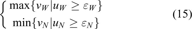
where εW is the accepted flattening of the minimum generalized external force ellipsoid, and εN is the accepted flattening of the minimum generalized internal force ellipsoid. εW and εN are given according to the specific problem. vW, uW, vN, and uN are the functions of
Optimal grasp planning method based on a task
The optimal grasp planning method based on a task is as follows. According to the shape of the object and the structure of the dexterous hand, describe the grasping configuration and positions of contact points with simple parameters, α1, α2 ⋯ αn. Calculate the grasping matrix Calculate the Jacobian matrix According to the contact model, calculate the Moore–Penrose generalized inverse, Calculate the length of each main axis of the generalized force ellipsoid, σ
Wi
and σ
Ni
. Calculate the grasping indicators, vW, uW, vN, and uN. Give the proper εW and εN, and obtain the feasible ranges Solve the optimal grasping parameters ϕbest in the feasible ranges to satisfy the maximum v
W and minimum vN, thus completing the grasp planning.
Simulation of grasp planning
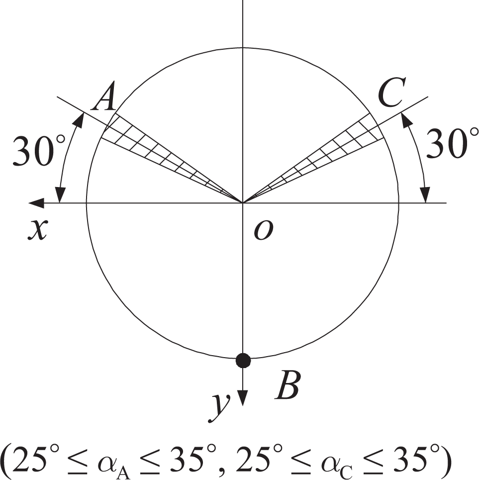
Figure 2(a) shows a three-fingered dexterous hand grasping a sphere with radius 0.025 m. The object coordinate system O − xyz has an origin at the center of the sphere, and the basic coordinate system B − XYZ has an origin at the center of the equilateral triangle ΔA′B′C′ (with side length c = 0.07 m). The three metacarpophalangeal joints are distributed on the vertices of the equilateral triangle, and local coordinate systems

Grasping a sphere with a three-fingered dexterous hand.
Denavit–Hartenberg parameters of finger links.

The grasping model is simplified as follows: The center of the sphere is immediately above the center of the equilateral triangle, at a distance l(m), and the matrix for the transformation between the coordinate systems O − xyz and B − XYZ is The three fingers change position along the edge of a sphere with radius R = 0.025 m. Contact point B is fixed, and its position vector in the object coordinate system O − xyz is Contact points A and C can be distributed along the edge of the sphere, as shown in Figure 2(b), and their relative positions are determined by αA and αC.
The grasping configuration and positions of contact points are completely determined by the three parameters αA, αC, and l. The three parameters should thus be planned reasonably to ensure the volume of the generalized external force ellipsoid is maximized and the volume of the generalized contact internal force ellipsoid is minimized.
On the basis of the contact matrices
On the basis of the finger Jacobian matrices
Simultaneously, let
The change in the grasping indicator with the parameters αA, αC, and l is analyzed as follows.
Fixing l = 0.08 m while changing αA and αC
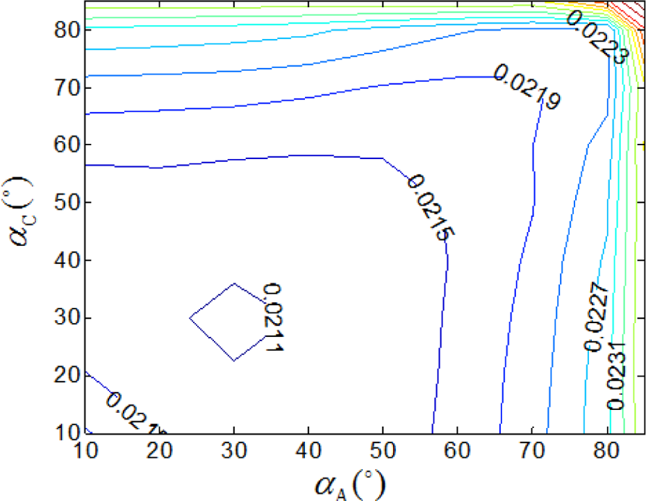
Figure 3 shows how the volume of the generalized external force ellipsoid vW varies with changes in αA and αC. The volume is a maximum in the shaded region, where vW ≥ 0.07; this shows the largest external grasping force that the object can resist. Figure 4 shows positions of contact points corresponding to the shaded region, where the volume vWmax is a maximum at αA = αC = 30°.

Variation of vW with αA and αC.
Grasping region for maximal vW.
Figure 5 shows how the flattening of the generalized external force ellipsoid uW varies with changes in αA and αC. The flattening is a maximum in the shaded region, where u W ≥ 0.4 and the grasping forces are transmitted evenly in all directions. Figure 6 shows the positions of contact points corresponding to the shaded region.

Variation of uW with αA and αC.

Grasping region for maximal uW.
If only considering the grasping indicators of the generalized external force ellipsoid, the region of overlap (
Figure 7 shows how the volume of the generalized contact internal force ellipsoid vN varies with changes in αA and αC. vN reaches a minimal value in the shaded region, where all values of vN are equal to or less than 0.014; this is the best situation for grasping. Positions of contact points corresponding to the shaded region are shown in Figure 8.

Variation of vN with αA and αC.

Grasping region for minimal v
N: (a) (
Figure 9 shows how the flattening of the generalized contact internal force ellipsoid uN varies with changes in αA and αC. uN reaches maximal values in the five shaded regions, where all values of uN are greater than or equal to 0.7. Figure 10 shows the positions of contact points corresponding to the shaded regions.

Variation of uN with αA and αC.
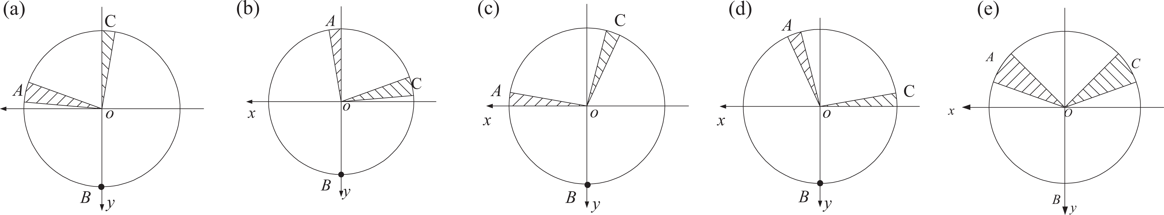
Grasping regions for minimal uN: (a) (
Because of the symmetrical distribution of the three fingers, the positions of contact points are distributed symmetrically not only between Figure 10(a) and (b) but also between Figure 10(c) and (d).
The regions of overlap between Figures 9 and 10 are
Considering both the maximum volume of a generalized external force ellipsoid and the minimum volume of a generalized contact internal force ellipsoid, the optimal grasping region is
Fixing
while changing l
If αA and αC are all 30°, the limited range of l can be obtained as 0.151 m ≥ l ≥ 0.065 m. The two limiting grasping configurations are shown in Figure 11.

Limiting grasping configurations.
Figure 12 shows how vw and uW vary with a change in l. First, vw has maximum values of 0.18 and 0.19 at the two limit positions l = 0.151 m and l = 0.065 m, respectively. For the configuration l = 0.11 m, vw has a minimum value of 0.041. Second, uW decreases with increasing l. Considering the variations of both vW and uW with l, both vW and uW have maximum values when l is at the limit position l = 0.065 m, where vw = 0.18 and uW = 0.5. Therefore, if only considering the grasping indicators of the generalized external force ellipsoid, the optimal grasping configuration is l = 0.065 m.

Variations of vW and uW with l.
Figure 13 shows how vN and uN vary with a change in l; both vN and uN increase with increasing l. We need to choose l = 0.065 m to minimize vN but also need to choose l = 0.151 m to maximize uW, which means that we cannot simultaneously get the minimal vN and the maximal uW. However, there is little change in uN, which ranges from 0.71 to 0.74, over the whole adjustable range of l. Therefore, if only considering the grasping indicator of the generalized contact internal force ellipsoid, the optimal grasping configuration is l = 0.065 m.

Variations of vN and uN with l.
The above simulation results of grasp planning reveal that the optimal grasping configuration and positions of contact points are
Grasping experiment
When the drive capability of dexterous hand joints is constant, the grasped object can resist stronger external forces from all directions if the grasping configuration and positions of contact points are optimized effectively. From another viewpoint, we can say that when the external forces acting on the grasped object are constant, the output torque of the dexterous hand joints will be weaker for the optimized grasping configuration and positions of contact points. Therefore, to validate the effectiveness of the grasping indicator proposed in the present article, it is only necessary to experimentally demonstrate that for the same grasped object and constant external forces acting on the object, the output torques of the dexterous hand joints will be weakest with the optimal grasping configuration and positions of contact points.
This section reports a grasping experiment using a three-fingered dexterous hand that grasps a sphere, as shown in Figure 14. The palm of the dexterous hand is placed horizontally on a table, the sphere is centered directly above the palm and has mass of 315 g, and the points of contact between the sphere and the middle finger, thumb, and index finger are denoted A, B, and C, respectively. For a fixed point B and

Grasp planning for a sphere.
Fixing l = 0.08 m while changing αA and αC
The positions of contact points A and C are changed at intervals of 10° in the experiment. A personal computer reads torque information from joint torque sensors communicating with joint servo control units through a controller area network. Root-mean-square values of the joint torques of the dexterous hand are calculated and given in Table 2.
Distribution of joint torques of grasping for different positions of contact points

Figure 15 is a contour map of the root-mean-square value of joint torques versus the position of the contact points. The root-mean-square value of joint torques reaches a minimum of 0.1897 N·m at
Variation of vW and uW with l.
Fixing
while changing l
Both αA and αC are fixed at 30° while the initial grasping configuration increases gradually from a minimum value of 0.065 m to 0.150 m in the experiment. Statistics of the joint torques are given in Table 3, while statistics of the contact internal forces, obtained by reading six-dimensional fingertip sensors, are given in Table 4.
Distribution of joint torques for different grasping configurations

Distribution of contact internal forces for different grasping configurations (N).

Figure 16 shows how the root-mean-square value of joint torques varies with a change in grasping configuration. The joint torques applied by the dexterous hand increase with increasing l. When the grasping configuration is at the minimum limit (= 0.065 m), the root-mean-square value of the joint torques applied by the dexterous hand is at a minimum.

Effect of the grasping configuration on joint torques.
Figure 17 shows how the root-mean-square value of contact internal forces varies with a change in grasping configuration. The contact internal forces increase with increasing l. When the grasping configuration is at the minimum limit (= 0.065 m), the root-mean-square value of the contact internal force is at a minimum.

Effect of the grasping configuration on contact internal forces.
Experimental results
The main findings of the experiments are as follows: The required joint torques are a minimum for l = 0.065 m and The contact internal forces acting on the sphere are a minimum for l = 0.065 m and A minimal root-mean-square value of joint torques of the dexterous hand and a minimal root-mean-square value of contact internal forces are obtained when completing the grasping experiment with the grasping configuration and positions of contact points optimized according to “Simulation of grasp planning” section. The effectiveness of the proposed grasping planning method was thus demonstrated.
Conclusions
Using the general solution of joint torque, the present article proposed a grasping indicator—the maximum volume of the generalized external force ellipsoid and the minimum volume of the generalized internal force ellipsoid during accepted flattening—and established an optimal grasp planning method based on the task. Simulation and experimental results showed that the optimal grasping configuration and positions of contact points could be obtained using the proposed grasp planning method.
Footnotes
Declaration of conflicting interests
The author(s) declared no potential conflicts of interest with respect to the research, authorship, and/or publication of this article.
Funding
The author(s) disclosed receipt of the following financial support for the research, authorship, and/or publication of this article: This research is supported by the National Natural Science Foundation of China (51305088) and the Natural Science Foundation of Heilongjiang Province, China (42400621-1-12069-01).