
Abstract
This article addresses the development and implementation of a test bed for applications of heterogeneous unmanned vehicle systems. The test bed consists of unmanned aerial vehicles (Parrot AR.Drones versions 1 or 2, Parrot SA, Paris, France, and Bebop Drones 1.0 and 2.0, Parrot SA, Paris, France), ground vehicles (WowWee Rovio, WowWee Group Limited, Hong Kong, China), and the motion capture systems VICON and OptiTrack. Such test bed allows the user to choose between two different options of development environments, to perform aerial and ground vehicles applications. On the one hand, it is possible to select an environment based on the VICON system and LabVIEW (National Instruments) or robotics operating system platforms, which make use the Parrot AR.Drone software development kit or the Bebop_autonomy Driver to communicate with the unmanned vehicles. On the other hand, it is possible to employ a platform that uses the OptiTrack system and that allows users to develop their own applications, replacing AR.Drone’s original firmware with original code. We have developed four experimental setups to illustrate the use of the Parrot software development kit, the Bebop Driver (AutonomyLab, Simon Fraser University, British Columbia, Canada), and the original firmware replacement for performing a strategy that involves both ground and aerial vehicle tracking. Finally, in order to illustrate the effectiveness of the developed test bed for the implementation of advanced controllers, we present experimental results of the implementation of three consensus algorithms: static, adaptive, and neural network, in order to accomplish that a team of multiagents systems move together to track a target.
Introduction
Recently, unmanned aircraft systems (UASs) require advanced features, in aerodynamic design and avionics systems, for performing different and complex tasks in places considered too dangerous for the human being. These tasks, which involve civilian and military applications, are most of the time related to monitoring and search and rescue. Some UAS applications require an effective guidance, navigation, and control of heterogeneous unmanned systems, which consist of multiple, small underground vehicles and small unmanned aerial vehicles such as quad rotorcrafts. Quad rotorcrafts can operate autonomously, receive missions from a ground station, and execute collaborative flight which demands a high computational cost from the onboard computers, communication devices, and actuators.
Diverse communication and control interfaces have been developed for quad rotorcrafts in order to collaborate and to execute complex missions. In the studies of Cavett et al. 1 and Visser et al., 2 the authors developed the communication and control interfaces for the AR.Drone. Gururaj et al. 3 controlled the AR.Drone position and velocity through a Visual C++ interface whose communication is implemented using the AT commands and the UDP protocol. A control interface was developed for a quad rotorcraft with fire detection capabilities by using Visual C and OpenGL in the study of Hernandez et al. 4 In this sense, a ground station for a quad rotorcraft, based on Java and Visual C++ software, was developed by Yang et al. 5 and Xiao-yan et al. 6 Mellado et al., 7 Zhekui et al., 8 and Garcia Carrillo et al. 9 developed an interface which uses computer vision and trajectory tracking for complex systems.
Indoor experiments for UASs applications are based on laboratory test beds which are used to implement control algorithms and to communicate and coordinate aerial and ground vehicles in a controlled environment. For instance, in the study of Ferrari et al., 10 the authors presented an approximate dynamic programing approach to cooperative navigation for heterogeneous sensor networks. Saad et al. 11 described a test bed that provides a cost-effective rapid prototyping capability for integrating health-based adaptive control of subsystems, vehicle, mission, and swarms to guarantee top-level system-of-systems performance metrics. A hardware test bed for multi-UASs that bridges the gap between algorithm design and field deployment is presented by Twu et al. 12 Bi and Duan 13 presented an implementation of a hybrid system consisting of a low-cost quad rotorcraft and a small pushcart.
In recent years, the formation control of multiagents system (heterogeneous and homogeneous) has been a very active research area. 14 The formation problem can be addressed, for example, by implementing consensus protocol strategies. This techniques enable a team of agents or vehicles to reach an agreement on certain states or values of interest, in such a way that the behavior of all the agents is the same. Olfati-Saber and Murray 15 presented a general framework for the consensus problem of n integrator agents with fixed and switching topologies. Zhang et al. 16 presented a consensus for linear high-order systems using state feedback and output feedback. Li and Duan 17 introduce and adaptive scheme in order to consider the effects of the weights links between the agents in the communication topology. In the study, Lv et al. 18 designed a robust adaptive consensus protocol for linear multiagents with uncertainties. In a more realistic scenario, the agents have uncertainties in their dynamics; to overcome this situation, Peng et al. 19,20 presented a distributed neural network for uncertain dynamical multiagent systems (MASs). In the aforementioned work, the authors proposed different consensus protocols like leader–follower, as well as different control techniques, to reach consensus. The works previously listed were validate by means of numerical results; however, a real-time implementation of these methods is not presented. Our work presents a functional test bed for implementation of this kind of consensus protocols, which aims at filling this research gap.
The main contribution of this article is the development of a laboratory test bed based on the Parrot AR.Drone and the Bebop Drone that allows users to choose between four different development environments for testing control algorithms involving more than one vehicle, as well as vehicles of different nature (heterogeneous systems). The four development environments differ each other either in the employed vehicles or in the software used for controlling them. The employed software includes LabVIEW (a graphical programing software) and robotics operating system (ROS, Open Source Robotics Foundation). Moreover, the test bed allows users to choose different ways of controlling vehicles based on the replacement of the original firmware which reads the raw data from sensors and controls directly the motors, or more intuitively, by using the available Parrot software development kits (SDKs) or drivers, which have been modified for accepting commands to communicate and control multiples drones. Figures 1 and 2 sketch the developed test beds for applications of vehicle tracking and multiagent application, respectively.

Test bed for applications of heterogeneous unmanned vehicle systems. Vicon cameras, AR.Drone, and Rovio ground vehicle.

Test bed for applications of multiple unmanned vehicle systems. OptiTrack cameras and Bebop Drones.
The rest of the article is organized as follows: “Test bed description” section presents the description of the main elements of the test bed. “Developed platforms” section describes the developed platforms by using the LabVIEW software, the ROS, and the method which does not use the Parrot SDK but uses a custom program. “MASs application” section presents the control law used to verify the effectiveness of the proposed test bed. Then, “Experimental results” section shows the numerical and experimental results obtained by using the test bed in a controlled laboratory environment. Finally, “Conclusion” section provides conclusions of this research work.
Test bed description
In this section, the components employed for the development of the test bed are presented. These components are a group of ground and aerial vehicles, a motion capture system, computers, and three software platforms to implement the heterogeneous unmanned vehicle system applications.
Motion capture systems
Two different motion capture systems were used in this work in order to obtain the vehicle’s position and orientation. Both system can be configured to use the Virtual-Reality Peripheral Network (VRPN) streaming protocol, making them compatible from a software point of view.
VICON
A Vicon Motion Capture System (VICON, Oxford, England, United Kingdom) composed of eight VICON Bonita-10 cameras. These cameras have a capture speed of up to 250 fps, which are transmitted through the VRPN network protocol to a computer running any software being able to establish a VRPN connection. Using this motion capture system, it is possible to track an object with a precision down to 0.5 mm of translation and 0.5° of rotation in a 4 × 4 m2 volume using 9-mm markers attached to the object.
OptiTrack
An OptiTrack Motion Capture System (NaturalPoint, Inc. Corvallis, Oregon, USA.) composed of 12 S250e cameras. These cameras are capable of capture speeds of up to 250 fps with the VRPN network protocol. Using this motion capture system, it is possible to track an object with a precision down to 1 mm of translation and 1° of rotation in a 9 × 7 m2 volume using 19-mm markers attached to the object.
Unmanned Aircraft Vehicle (UAV) description
The UAVs employed for the implementation of algorithms in the proposed test bed were the Parrot AR.Drone version 2, which is a quad rotorcraft controlled through a Wi-Fi connection. The technical characteristics of this vehicle, such as the processor type and sensors, can be found in the studies of Bristeau et al. 21 and Montufar et al. 22 We have selected the AR.Drone to develop the proposed platform since it is a low-cost platform, very resistant to damages from crashes.
In order to use the AR.Drone for custom applications, two approaches are available: (i) an SDK and (ii) the original program of the AR.Drone replacement. The SDK is presented in the next subsection, as it is common to both LabVIEW (see “LabVIEW platform” section) and ROS (see “ROS platform” section) methods. Program replacement is described in “Original firmware replacement platform” section.
Parrot AR.Drone SDK
The AR.Drone creates its own Wi-Fi network, and, using the user datagram protocol (UDP), it receives command signals generated by a device connected to the network. Likewise, by means of the UDP protocol, the AR.Drone shares its navigation information (telemetry). The information exchange is carried through three ports: 5554, 5555, and 5556, which are used for (i) navigation data reception, (ii) video package reception, and (iii) command control transmission and parameters configuration, respectively.
The SDK provided by Parrot is a set of libraries that allow us to communicate with the AR.Drone by an external device in order to get the navigation data and video package allowing the host computer to configure and to control the AR.Drone. The core of the SDK is the attention commands (AT), which are composed by the string “AT*” plus the command name followed by the equal sign, and finally by a sequential number and an optional arguments list. Table 1 shows the more useful commands to manipulate the Parrot AR.Drone by using the SDK. A detailed description of such commands can be found in the work of Piskorsky et al. 23
AR.Drone AT commands.

Bebop autonomy SDK for Bebop Drone
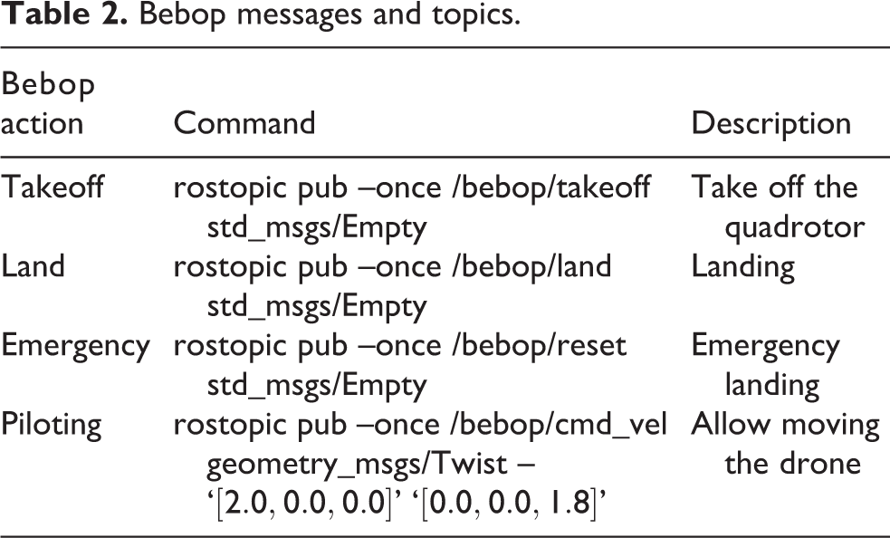
Bebop_autonomy is an ROS driver for controlling the quad rotorcraft Parrot Bebop 1.0 and 2.0, based on Parrot’s official ARDroneSDK3. The Bebop’s driver can run as a node in an ROS environment. The executable node is called bebop_driver_node which exists in the bebop_driver package. The core of the bebop_autonomy ROS driver is messages of type std_msgs/Empty, which are used to publish to topics takeoff, land, and reset. Also, the message geometry_msgs/Twist is employed to publish to topic cmd_vel while the Bebop is flying. Table 2 shows the topics used to control the Bebop Drone and their syntax employed.
Bebop messages and topics.
Developed platforms
LabVIEW platform
In order to develop algorithms for the AR.Drone by using the software LabVIEW, it is necessary to download and install the AR.Drone Toolkit LVH through the virtual instrument (VI) Package Manager, provided by National Instruments (Austin, Texas, USA). After installation, the AR.Drone Toolkit palette will be available in LabVIEW. In this palette, there are VIs that allow us to start and close the communication with the vehicle, called Open VI and Close VI, respectively. The Control Drone VI is used to control operations such as the takeoff and landing, hover mode, emergency landing, and movement commands. In order to obtain the navigation data of the AR.Drone, the Initialize NavData and Read NavData VIs are used. The provided information consists of the Euler angles and angular velocities, principally. Using these VIs, it is possible to develop a graphical user interface (GUI) in LabVIEW to control and visualize information of the PArrot AR.Drone.
Algorithm 1 summarizes all the required steps in order to carry out the control and visualization of the parameters of the AR.Drone in a GUI. In the study of Montufar et al., 22 an example of a GUI developed to control the drone in LabVIEW is presented.
Controlling the AR.Drone from LabVIEW

In order to establish a connection between LabVIEW and the VICON system, it is necessary to download and install the VICON DataStreamSDK, provided by the VICON Company (Oxford, England, United Kingdom). To use the SDK, the library ViconDataStreamSDK DotNET.dll (DS-SDK) is needed, which is included in the installation folder. Then, it is needed to use .NET connectivity for adding a reference to .NET assembly.
Once the above steps are performed, it is possible to use the functions included in the SDK, which allow to connect with and to request data from the VICON DataStream.
Algorithm 2 summarizes the required steps to get the object’s (in this case, a robot) position and orientation from the Vicon Motion Capture System by using the LabVIEW software.
Obtaining object’s position and orientation in LabVIEW

Configuration of multiple AR.Drones in LabVIEW
In order to design a LabVIEW program that allows us to manipulate multiple AR.Drones connected to a single personal computer (PC) at the same time, the PC and all the vehicles must be connected to the same router. This section explains how to develop the required procedure. On the one hand, users have to modify the network configuration for each drone. To configure the vehicle’s network, it is necessary to make a connection to the drone’s IP address 192.168.1.1 through a telecommunication network (TelNet) protocol and execute the next commands:
The previous configuration removes the AR.Drone Wi-Fi network and establishes a connection between the AR.Drone and the router specified by the network name parameter (ESSID). The other parameters that the user needs to modify are the IP address of the drones (a different address for each drone) and the subnet mask according to their own network configuration. It is also necessary to modify some parameters of the Open VI provided in the AR.Drone Toolkit LVH. The parameter to be modified is the IP address, which must be assigned accordingly to the configuration previously done for the drones. Furthermore, it is necessary to modify the address of ports: Home Command Port, Home NavData Port, and Home Vid Stream Port, which have to be different for each drone.
ROS platform
ROS is an open-source framework, metaoperating system that is widely used in robotics, see, for example, the studies of Mason and Marthi, 24 Hornung et al., 25 Mellinger and Kumar, 26 Grabe et al., 27 and Martinez and Fernandez. 28 The objective of ROS is to make a piece of software that could work in diverse robots by making little changes in the code. The ROS advantage is to provide standard operating system facilities such as hardware abstraction, low-level device control, implementation of commonly used functionalities, messages passing among process, and package management. ROS also provides tools and libraries in order to obtain, build, write, and run code across multiple computers. ROS is released under the terms of the Berkeley Software Distribution license.
In this work, the package named ardrone_autonomy is used, which employs the SDK 2.0.1 in order to command the Parrot AR.Drone versions 1.0 and 2.0. The node created from the ROS package is the ardrone_driver. This package uses dependencies such as roscpp, image_transport, sensor_msgs, camera_info_manager, and std_srvs (which are employed for programing on C++ language) to transport images in low-bandwidth compressed formats, to create messages for sensors, and to calibrate the cameras, respectively. Before running any package, it is necessary to execute the roscore command since it is a collection of nodes and programs necessaries in an ROS-based system.
The package ardrone_autonomy consists of 4 input topics and 28 output topics. The input topics include the /ardrone/reset (emergency), /ardrone/land (landing), /ardrone/takeoff (takeoff), and /cmd_vel (roll, pitch, yaw, and thrust), while the output topics provide the navigation and camera data.
If the navigation data (telemetry) is required, it is necessary to create a node subscriber, which is the bridge between the information of the ardrone_autonomy and the user’s application. However, a simple way to visualize the data is to read the topic in a terminal by using the command line rostopic list. The /ardrone/navdata topic displays the information of the battery level, the agent’s position in x, y, and z axes, the angular position (roll, pitch, and yaw), the altitude, the atmospheric pressure, and other state variables, which, by setting the navdate_demo parameter, can be configured to be transmitted at frequencies between 15 Hz and 200 Hz.
Once all the parameters listed above have been configured, it is possible to develop a program under the ROS environment that allows us to control the Parrot AR.Drone. This procedure provides a tool with the possibility of controlling the takeoff, landing, emergency, and the four control signals (roll, pitch, yaw, and thrust), with values from −1 to 1.
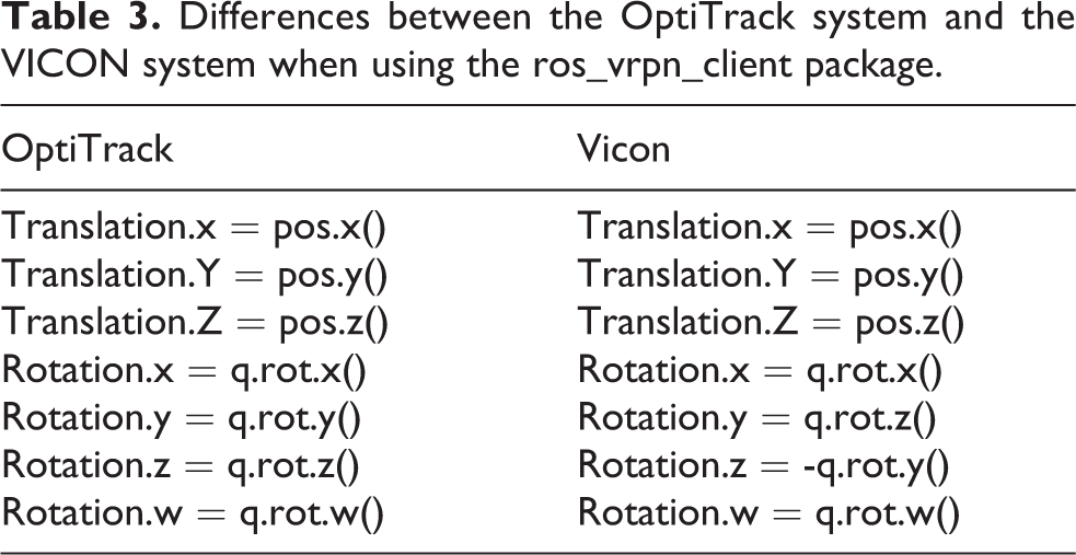
In order to get the vehicle’s x, y, and z positions, we use the motion capture system which provides the position and orientation of the vehicle through the communication protocol VRPN. This protocol is a set of classes within a library, and a set of servers interface between application programs and the set of physical devices use in a virtual-reality system. In order to use this communication protocol, ROS employs the package called ros_vrpn_client which is a client for VRPN and publishes a transformation frame and TransformStamped of the tracked vehicle. In this sense, it is important to mention that this package was developed to work using the OptiTrack cameras system, but it could be modify to work using the Vicon cameras system. To change the motion capture system platform, it is necessary to arrange the position of the quaternions since the Vicon cameras system gives a different arrangement than the OptiTrack cameras system (see Table 3).
Differences between the OptiTrack system and the VICON system when using the ros_vrpn_client package.
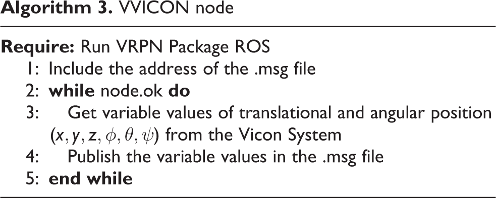
Once this procedure has been done, it is necessary to create a new package to control the AR.Drone using the ardrone_autonomy and ros_vrpn_client packages and implementing the different algorithms (Algorithms 3 and 4). These packages read the information provided in a file .msg created for the ros_vrpn_client package, which contains the position of each vehicle. In addition, the information of each vehicle, such as the battery percent, signals of the package with the topics /ardrone/takeoff, /ardrone/land, /ardrone/reset, and /cmd_vel are available to control the vehicle. Additionally, this package converts from quaternions to Euler angles using ROS commands.
VVICON node
Main Package ROS
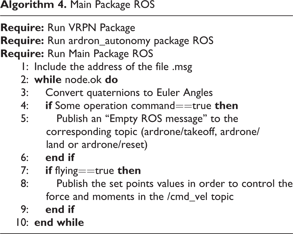
Figure 3 depicts the test bed hardware and software components required for the ROS environment. The program has been tested at different frequencies such as 30, 50, and 100 Hz. It is worth mentioning that some disconnection problems were observed at 100 Hz.
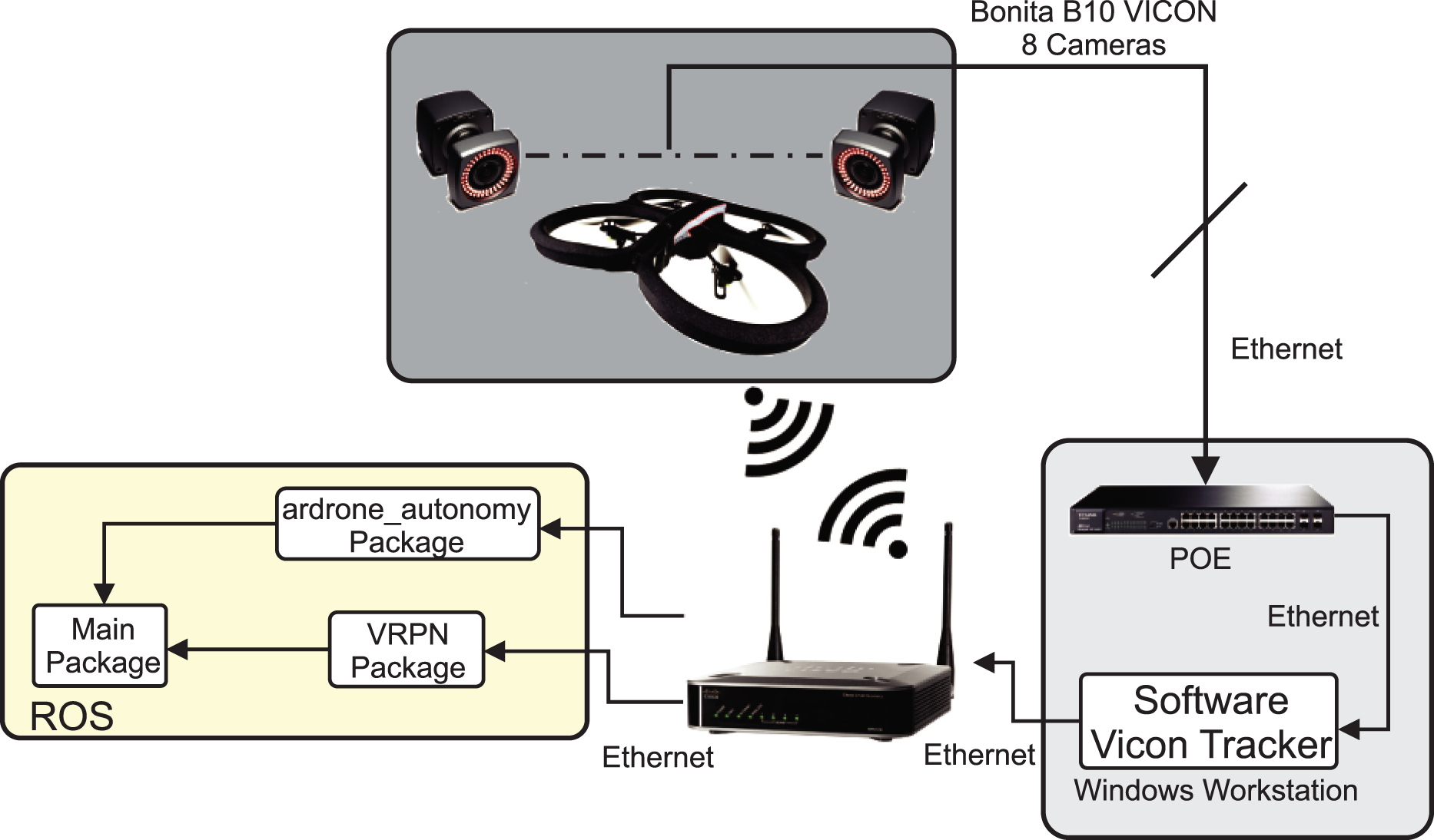
Nodes used in ROS. ROS: robotics operating system.
Configuration of multiple AR.Drones
To employ multiple drones, it is necessary to change the default network configuration of the vehicle, since from factory the drone creates its own network to establish a connection with an Android or iOS device. In order to change the default configuration network of the AR.Drone, the TelNet protocol is required, which enables to connect remotely to the embedded operating system of the drone (based on Linux version 2.6.32), as it was described in the previous section. In this sense, the vehicles must be connected to a router in order to control multiple drones with a single PC. Once the vehicles are connected to the router, we need to change the SDK 2.0.1, which is located inside the package of ardrone_autonomy. This procedure is needed due to an issue that does not allow the connection of two or more AR.Drones using the same package. To solve this problem, we need to access the file called vp_com_socket.c, which is located in the path of ARDroneLib/VP_SDK/VP_Com, and to replace the line of code 90, which is:
with this code
and then, to compile the package again.
Configuration of multiple Bebop Drones
To employ multiple Bebop Drones (1.0 or 2.0), it is necessary to perform the following steps: For each one of the Bebop platforms to use, a Bebop Autonomy ROS package must be installed, changing only the installation directory. All the instructions to install and compile the Bebop Autonomy ROS package are found in the web page
http://bebop-autonomy.readthedocs.io/en/latest/index.html
For each one of the Bebop platforms, change the communication port in the Bebop ROS package. In order to do this, change the file ARDISCOVERY_DEVICES_wifi.c located in #define BEBOP_DEVICE_TO CONTROLLER_PORT 43210 Next, it is necessary to rebuild the package. Change the network configuration, converting Bebop to client instead of access point. To make the Bebop Drone join an access point instead of broadcasting its own SSID, the following script must be added in the file /bin/onoffbutton/longpress_0.sh. When the power button is pressed for about 5 s, the drone will then connect to the access point.
Original firmware replacement platform
The last method presented in this article is to completely turn off all original programs of the AR.Drone. By doing this, it is possible to directly control the motors or read raw data from all sensors.
The motors’ drivers (Brushless DC [BLDC]) of the platforms are connected to the same serial port on the main board of the UAV. By writing on this port, it is possible to send a kind of broadcast with all four values, allowing to control the speed of the motors. Note that BLDCs accept values from 0 to 1023 and convert them in a rotation speed reference. Note that the BLDCs of this platforms work in speed regulation, not in power regulation like many other platforms. The main board is connected to the navigation board with a serial port. This navigation board includes a programmable interface controller (PIC) microcontroller, a three-axis accelerometer, a three-axis gyrometer, a three-axis magnetometer, a barometer, and an ultrasonic sensor. The PIC microcontroller delivers raw data for all sensors at 200 Hz, except for the ultrasonic sensors which runs at 25 Hz. The AR.Drone also includes two cameras, which are connected to a dedicated bus and to an image signal processor. These onboard cameras where not implemented in this work. For more details on the protocols of the serial ports, the interested reader is referred to “Work on Paparazzi from MAV Lab.” 29 Turning off original programs is very simple and is done by commenting, in the startup scripts, the call to program.elf. With this approach, the SDK from Parrot is not used, and user-developed programs run directly on the embedded computer.
By using the original SDK, we can only use Parrot’s control laws. Therefore, the main advantage of the methodology proposed here is that it allows the user to completely redefine the control laws for roll, pitch, yaw, and thrust. For example, in this work, control laws based on separated saturation functions were implemented. 30 However, one possible limitation is that the user loses sensor fusion capabilities executed by the original program. Indeed, sensor fusion is performed between inertial sensors and cameras, which provides an accurate estimation of the platform’s attitude. In the proposed methodology, a complementary filter was implemented using inertial sensors, 31 which is close but not as accurate as the filter developed by Parrot.
Protocols for writing to motors’ controllers and reading from sensors were integrated in the framework available at one of our laboratories. This framework, which is written in C++ and includes libraries for all kind of filters and sensors, allows to easily write applications for UAVs. Then, integration of sensors, actuators, and filters is straightforward, and each of them can be linked to a different module automatically. The framework also manages the ground station, and then, the programmer does not have to worry about how to exchange information between UAV and ground station. The framework sends data to the ground station (for plotting), and each item’s configuration (sensor, filter, and other modules) can be modified from the ground.
Moreover, a simulation environment allows to analyze previously the performance of the scripts executed onboard the real UAV platforms, but in a ground station computer. The aim is to test the programs of all UAVs in a single computer, in order to verify that there are no bugs in the code and that everything is working as expected. Therefore, the simulation environment avoids unnecessary crashes on real flights and saves time on the developments. The simulator uses a three-dimensional world (see Figure 4), where it is also possible to obtain virtual pictures of the embedded cameras in order to test image processing algorithms.

Simulation environment. The program to be used in the real-time application (see “Experimental results” section) is tested first here.
In the developed framework, base classes are defined for each kind of sensor, and then, small modifications are implemented for specific sensors of each UAV. Thus, the use of a particular sensor is transparent for the programmer, as it is possible to use the application program interface for the generic sensor. In this way, programs are exactly the same, despite the kind of platform being used (AR.Drone, homemade UAV, or simulation). Note that the AR.Drone version 2 was used for experiments of the proposed method, but it is possible to reproduce the same tasks with AR.Drone version 1.
MASs application
The real-life applications for the proposed test bed are the MASs, homogeneous or heterogeneous. MASs are composed of multiple interacting elements known as agents. Agents are equipped with computer systems having two important capabilities. First, they are capable, at least to some extent, of autonomous action. Second, they are capable of interacting with other agents, in tasks such as cooperation and coordination.
In order to realize coordination tasks, consensus is one of the most employed frameworks in MASs. Consensus is commonly needed in mobile robots, unmanned air vehicles, autonomous underwater vehicles, satellites, aircraft, spacecraft, and pay load transportation. Because of the importance of the consensus approach, this work demonstrates the application of three different consensus strategies in the laboratory test bed presented in the previous section.
This section starts with preliminary concepts related to consensus theory. Additionally, the implemented MAS mathematical model is introduced. Finally, the three consensus strategies to be implement are presented.
Graph theory
In order to develop a consensus control protocol, it is necessary to define the allowed information flow between the agents. A communication graph is used to describe the information exchange between the agents in the MAS as well as with the MAS leader. For this reason, a brief description of graph theory is presented below.
Let
The set of neighbors of node i is denoted by

A new augmented Laplacian matrix

where the terms aij
are the elements of an adjacency matrix

The consensus control protocols implemented in this work use the concepts of graph theory previously defined and the mathematical model of the agents. In the next subsection, the mathematical model of the dynamics of each agent of the MAS is introduced.
Mathematical model of the MAS
Consider an MAS consisting of N agents and one leader. In order to represent the agents’ heading angle (ψ), the dynamics of the i th agent can be described as

where xi ∈ ℝ n is the state vector of agent i, ui ∈ ℝ p is the corresponding control input vector, yi ∈ ℝ q is the agent’s measurement output vector, and A, B, and C are constant matrices with compatible dimensions. The dynamics of the leader, labeled as i = 0, are given as

where x 0 ∈ ℝ n is the state of the leader.
Definition 1
The leader-following consensus problem with a desired formation of the MAS represented by equations (1) and (2) is said to be solved if for each agent i ∈ {i, … ,N}, there is a local state feedback ui such that the closed-loop system satisfies
for any initial condition xi (0), with i = 0, 1, … , N.
Once defined the mathematical model of the agents’ heading angle, a set of three different consensus protocols (static leader–follower consensus, adaptive leader–follower consensus, and neural network leader–follower consensus) are defined in the next subsection.
Leader–follower consensus MAS protocols
In this subsection, we describe the proposed protocols employed to validate the effectiveness of the developed test bed. The goal consists of a group of followers agents tracking a leader while achieving a desired formation. In this scenario, we have proposed three different control laws which have been implemented by using Bebop Drones and the motion capture system OptiTrack.
Static leader–follower consensus
In distributed controller applications, the control law of each agent only uses local neighborhood information according to the topology of communication. In this sense, if the controller’s gains c and K are fixed at all time, such controller is called as a static leader–follower consensus controller and can be written as follows 16,32

The gain K in equation (3) is found as K = −R −1 BTP, where P = PT is the unique solution of the algebraic Riccati equation

with Q = QT and R = RT being positive definite matrices.
Adaptive leader–follower consensus
Parameter c in equation (3) is a global information; therefore, such protocol cannot be implemented in a fully distributed framework. In order to overcome this disadvantage, an adaptive scheme can be proposed where the gains cij represent a time-varying coupling weight for each edge (i.e. each communication link) and are update dynamically. Equation (4) shown the adaptive leader–follower consensus protocol 17

In equation (4), γ i0 and γij are scalar tuning positive parameters. The gains K and Γ are calculated as K = −BTP −1 and Γ = P −1 BBTP −1, where P = PT > 0 is a solution of the linear matrix inequality AP + PAT − 2BBT < 0.
Neural network leader–follower consensus
On the other hand, since the dynamical model given by equation (1) does not considers unmodeled dynamics, a valid approach is to employ a scheme that employees a neural network in order to identify and to compensate such unmodeled dynamics. Equation (5) shows the neural network leader–follower consensus protocol 19,20 used in this work

In equation (5),

where Q = QT is a positive definite matrix. A detailed analysis of this consensus protocol can be found in the study of Peng et al. 19,20
The development of the three consensus protocols presented in this section has been studied in previous works. However, to the best of the authors’ knowledge, these three protocols in particular have not been implemented in a real-time setup. In the next section, a set of experiments performed in a team of UASs are presented, and the results obtained are discussed.
Experimental results
In order to validate the effectiveness of the developed test bed, a set of experiments were performed for both the Parrot AR.Drones as well as for the Bebop Drones. The first set of experiments used the two AR.Drones aerial vehicles, labeled UAV1 and UAV2, for performing the tracking of a terrestrial or aerial vehicle, labeled Rovio or UAV0, respectively. These experiments were implemented by using the ROS, LabVIEW, and the original firmware platforms previously described.
In the developed experiments, the target vehicle (Rovio or UAV0) has to reach four waypoints arranged in a square of 1 × 1 m2, while the drones UAV1 and UAV2 track the target vehicle’s position and orientation (yaw angle) at 0° (back) and 180° (front), respectively. When the target vehicle reaches a waypoint, it turns 90° on its z-axis and continues to the next waypoint.
Algorithm 5 presents the steps to implement the above experiment.
Procedure for the implementation of Heterogeneous Unmanned Vehicle Systems application by using two AR.Drones, one Rovio vehicle, and ROS and LabVIEW platforms.

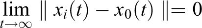
Figures 5 and 6 show the results obtained from the implementation of the proposed algorithm in a scenario where two aerial vehicles are tracking the orientation of a ground vehicle. The yaw angle of the ground vehicle is depicted as a red line, while the yaw angle of the drones UAV1 and UAV2 is depicted as a green and red line, respectively. It can be seen that the difference between the orientation of the ground vehicle and the orientation of vehicle UAV1 is kept near to π radians, because it is desired that the UAV1 observes the front of the ground vehicle at all time. The desired position for drone UAV2 is behind to the ground vehicle Rovio; for this reason, the red line seems to be following the blue line, corresponding to the yaw orientation of the ground vehicle.
Experimental results obtained from the ROS platform. Ground vehicle’s path (blue line), UAV1’s path (green line), and UAV2’s path (red line). ROS: robotics operating system.

Experimental results obtained from the LabVIEW platform. Ground vehicle’s path (blue line), UAV1’s path (green line), and UAV2’s path (red line).
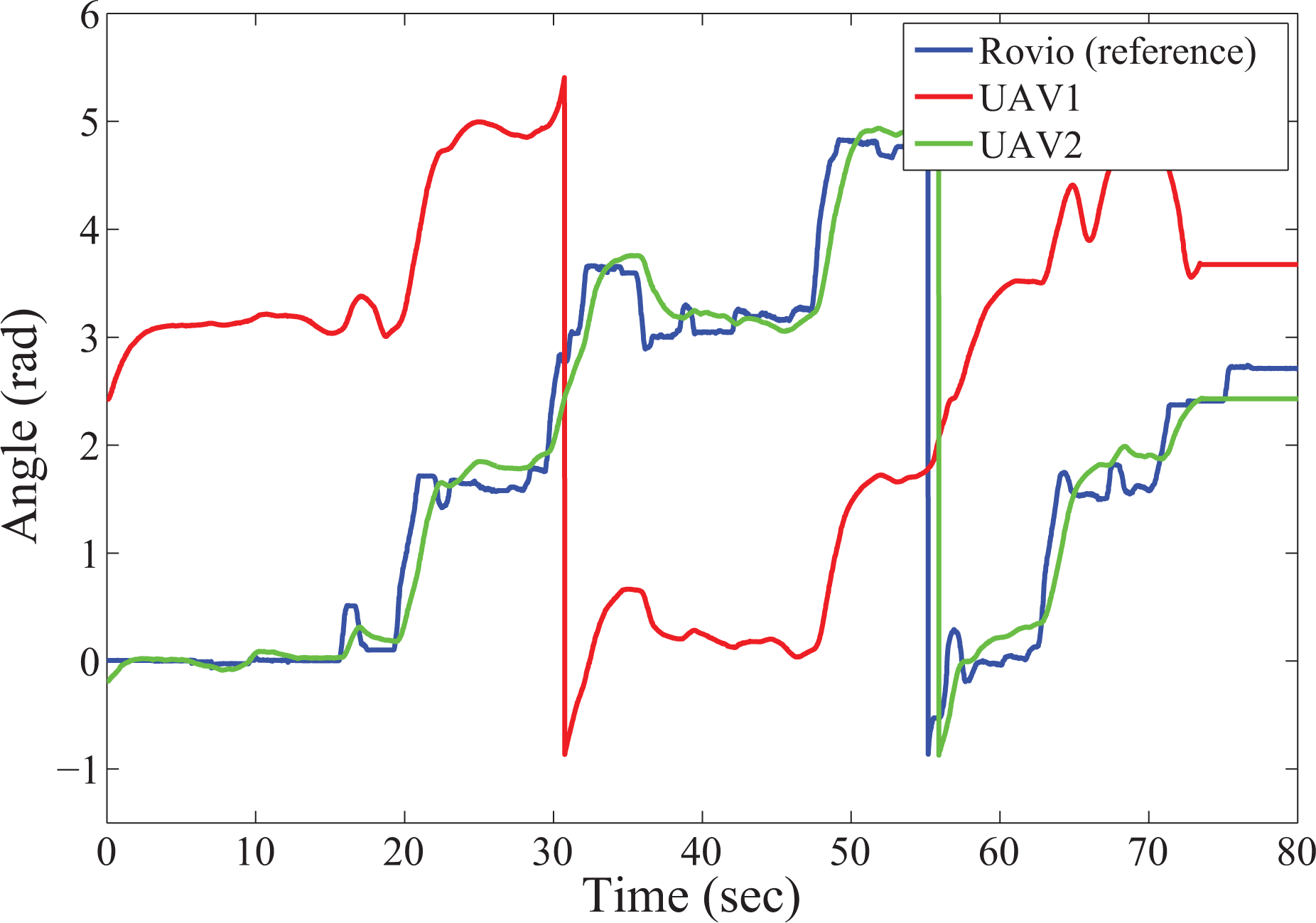
Similarly, Figure 7 shows the yaw angle of three AR.Drones obtained from the experimental results of the program replacement approach. In this scenario, UAV0 is the reference drone, and it also has to reach four waypoints on a square of 1 × 1 m2 . UAV1 and UAV2 are following the UAV0 with a fixed offset in yaw angle. We can notice from this figure that at time 7 s, 8 s, and 34 s, the motion capture system is giving a wrong estimation of UAV0’s yaw angle. In fact, it always occurs when the UAV is flying close to a wall, where some cameras (placed in this wall) cannot track it. Moreover, some markers (the ones close to the wall) are thus not well tracked by the other cameras. Then, the detected pattern is ambiguous, leading to a wrong estimation of the yaw angle by the motion capture system. Indeed, the resulting pattern is not a random one, and a rotation of π/2 in the z-axis leaves it unchanged. This can be seen in the figure, as the yaw angle is going from π/2 to 0. Moreover, since the wrong data is only a few samples (only four samples of a total of 6000), it does not affect considerably the UAV1 and UAV2 performance.
Experimental results obtained from the firmware replacement method. Ground vehicle’s path (green line), UAV1’s path (green line), and UAV2’s path (red line).
Finally, Figure 8 shows the paths of the vehicles when performing the experiment by using the Vicon Motion Capture System and the ROS platform. The blue line represents the ground vehicle’s path, which is trying to follow a square of 1 × 1 m2. Green line and red line represent the UAV1 and UAV2 paths, respectively. From this figure, we can see that the aerial vehicles move in a semicircular path when the ground vehicle rotates 90°, which is the desired performances, since the main goal of the experiment is to track the ground vehicle’s position and orientation.

ROS platform—vehicle’s paths in 2-D. Ground vehicle’s path (blue line), UAV1’s path (green line), and UAV2’s path (red line). ROS: robotics operating system.
The following link directs to a video that shows the implementation of the conducted experiments: http://youtu.be/2fGTtKEXsPY
The next subsection presents the experimental results of the tests performed using the Bebop Drone for applications of multiagents systems.
Consensus algorithm for controlling the heading angle of four Bebop Drones
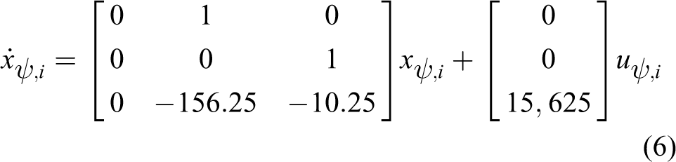
As previously described, one of the main advantages of Bebop Drone is that it allows testing advanced control algorithms at a low price at indoor environments. This advantage is exploited by the fact that it is possible to concentrate our attention on the stabilization and control of the dynamics related to the UAS’s heading angle and translational positions, leaving the embedded inner control loop to take care of the vehicle’s attitude stabilization. Toward this end, we used a modeling procedure which is based on the step response methodology, and whose detailed description can be found in our previous work. 32 The dynamic model employed in this article to derive the proposed control laws corresponds to the heading angle (ψ) of a Bebop quadrotor and can be written as follows:
Dynamic model for heading angle (ψ)
Once the dynamic model has been obtained, it is necessary to derive the gains values of the consensus control algorithm presented in equations (3) to (5). In this sense, the employed gains K and Γ are given by

Finally, the communication topology employed in this work is presented in Figure 9, from where it can be observed the four follower agents and their corresponding interaction; in this topology, the leader (labeled as 0) sends its information only to agent 1.

Communication topology.
Figures 10 to 13 show the results of the implementation of the consensus strategies given by equations (3) to (5). As can be seen, in the three experiments, the initial conditions for the agents were the same. In Figure 10, the result of the static consensus algorithm given by equation (3) is shown, where it can be observed that there exists a tracking error between the agent followers and the leader agent. This error is presented in all the experiment because the employed gains are constants. The results of the adaptive consensus presented in equation (4) are shown in Figure 11, and it can be appreciated that the tracking error is bigger than in the case of the static consensus; however, the tracking error decreases with time because in this case the gains are being adapted at every iteration. The implementation results of the neural network consensus protocol given by equation (5) are presented in Figure 12, and we can see that the neural network consensus protocol presented the smallest tracking error of the three protocols, tracking the reference in a better way. Finally, the tracking error between the followers and leader for each experiment is presented in Figure 13.

Heading angle behavior using static leader–follower consensus.

Heading angle behavior using adaptive leader–follower consensus.

Heading angle behavior using neural leader–follower consensus.

Tracking error of the heading angles for the three consensus controllers.
Conclusion
In this article, the development of an experimental test bed for applications involving heterogeneous unmanned vehicle systems was presented. The test bed consists of four different variations of a laboratory setup, which considers the use of aerial vehicles (Parrot AR.Drone and Bebop Drones) as well as ground vehicles (Rovio). The laboratory platforms enable the end user to choose between using a graphical programing software (LabVIEW), a Linux-based operating system (ROS), or to replace the original software of the AR.Drone for implementing novel control algorithms in multiple vehicles. Diverse algorithms were described for configuring both the vehicles as well as the motion capture systems (VICON or OptiTrack), which allowed a simple setup procedure to communicate with the employed unmanned vehicles. Finally, a set of experimental results were included to show the effectiveness and the usefulness of the proposed platforms.
Footnotes
Authors’ Note
This article is a revised and expanded version of a paper entitled: “Multi-UAV test bed for Aerial Manipulation Applications” presented at The International Conference on Unmanned Aircraft Systems (ICUAS), Orlando, FL, USA, 2014.
The author Luis Rodolfo Garcia Carrillo is now affiliated to Department of Electrical Engineering, Texas A&M University-Corpus Christi, College of Science and Technology, 6300 Ocean Drive, Unit 5797, Corpus Christi, TX, USA.
Declaration of conflicting interests
The author(s) declared no potential conflicts of interest with respect to the research, authorship, and/or publication of this article.
Funding
The author(s) disclosed receipt of the following financial support for the research, authorship, and/or publication of this article: This work was partially supported by the Mexican Program PRODEP UPPACH-004 Grant, by the Project Red Temática de Sistemas Autónomos y Ciber-Físicos, and by the Mexican National Council for Science and Technology Grant 263777. This work has been partially sponsored by the French government research program Investissements d’avenir through the Robotex Equipment of Excellence (ANR-10-EQPX-44). This work was carried out in the framework of the Labex MS2 T, which was funded by the French Government, through the program Investments for the future managed by the National Agency for Research (Reference ANR-11-IDEX-0004-02).