
Abstract
This article presents the design and experimental testing of a unidirectional variable stiffness hydraulic actuator for load-carrying knee exoskeleton. The proposed actuator is designed for mimicking the high-efficiency passive behavior of biological knee and providing actively assistance in locomotion. The adjustable passive compliance of exoskeletal knee is achieved through a variable ratio lever mechanism with linear elastic element. A compact customized electrohydraulic system is also designed to accommodate application demands. Preliminary experimental results show the prototype has good performances in terms of stiffness regulation and joint torque control. The actuator is also implemented in an exoskeleton knee joint, resulting in anticipant human-like passive compliance behavior.
Introduction
In recent years, there has been great interest in the promising field of human–robotic interaction (HRI) robotic system. As a typical “physical HRI” system, robotic exoskeleton is designed to assist the wearer in the case of a diminished functionality to stand and locomotion or to augment the performances of an able-bodied wearer. These devices are required to mechanically compatible with human anatomy without obstructing or resisting movement. 1,2 Some of them, such as leg exoskeletons, are also demanding adjustable passive compliance for adapting to the changes in environmental conditions and minimizing the energy consumption in periodic motions, such as walking. 3 Traditional stiff actuators designed for precise position control are not ideal options for HRI tasks. When the interaction involves an impact or kinetic energy transfer, traditional actuators show high impedance due to intrinsic rigid property and large inertia. Furthermore, although active compliance control approach, such as impedance control, can be used to regulate the mechanical impedance of actuators, even most robust systems are subject to unpredicted results from electrical, sensor, or software faults. All these disadvantages can lead to unpredicted collisions and the potential risk of injury. 4
Currently, a new approach to providing the variable stiffness by mechanically compliant actuator designs with a redundant actuation for passive compliance adjustment was proposed for HRI tasks, such as exoskeletal joint actuation. Dynamic control of joint stiffness can enable powered wearable devices to be incorporated into the everyday life activities of wearers, particularly for leg exoskeletons whose joint stiffness is required to be varied according to the gait, payloads, or other environmental requirements.
A number of electric designs with variable stiffness ability have been developed for bionic joints actuation. MACCEPA or the so-called “mechanically adjustable compliance and controllable equilibrium position actuators” characterized by a structure-controlled stiffness approach can change joint compliance based on the pretension variation of a torsion spring situated in a lever mechanism. 5,6 In the study of Chakarov et al., 7 an innovation design based on a leaf torsion spring with variable length allows a better performance of the joint, including a wide range of stiffness regulation at decoupled stiffness and position control. Another type of actuators with adjustable stiffness based on mechanically controlled stiffness adjusts the effective physical stiffness of the system by varying the fixation points of the elastic elements. In the study of Jafari et al., 8 actuator with adjustable stiffness (AwAs) regulates the compliance by controlling the location of the springs and adjusting its arm length. An improved version of this original realization, AwAS-II, regulates the compliance by adjusting the location of the pivot point. The latter can achieve the force amplification ratio from zero to infinitive; consequently, the level of stiffness can tune from very soft to completely rigid. 9 Another kind of design uses a pair of coupled antagonistically actuators with nonlinear quadratic elastic elements to realize linear force–displacement characteristics of joint. The equilibrium position of the joint is changed when both actuators move in the same direction, while the stiffness will be changed when they move in the opposite direction. 4,10
Some existing designs have shown significant improvements in meeting the requirements of assistive devices 11 and rehabilitation exoskeletons, 12,13 but the disadvantages are also obvious. Due to the large inertia of gear reducers for magnifying the output, the back-drivability of joints usually achieved by continuous active feedback control. Even when the joint is unloaded, a zero-force control is necessary for controlling the joint to follow the motions of wearer’s limbs. Although compact disk motors and gear reducer can be used, the size and mass of these designs are considered excessive. The components paralleling to the joint increase the lateral size of device and result in a bulky joint.
This article presented the design and experimental testing of a unidirectional variable stiffness hydraulic actuator (UVSHA) conceived as the joint actuator for a load-carrying knee exoskeleton. The specifications of UVSHA are designed based on knee biomechanics in locomotion and the unique requirements for load-carrying application. The proposed design incorporated a variable stiffness mechanism based on the concept of variable lever ratio into powerful hydraulic transmission. This will allow a wide range of stiffness regulation and active torque control with good fidelity by decoupled control of stiffness and joint torque. Numerical and physical experiments are performed. The results of this study may be useful for designers to develop hydraulic joints with variable stiffness for wearable devices.
Biomechanics of knee in locomotion
It is useful to review the biomechanics of knee joint to further the understanding of the physical requirements that a knee joint should fulfill in daily life and improve the design of assistive devices.
Role of knee in locomotion
According to the clinical gait analysis pattern, the gait cycle of human in level walking can be divided into two main phases: stance phase that starts with the heel strike and ends with the toe-off and swing phase that spans the rest of gait cycle until the next heel strike. 14 The knee plays an important role during the execution of gait. In stance phase, the knee decelerates and supports the body weight after heal strike and promotes it forward along a spatial ballistic trajectory. After acting as a shock damping mechanism at heel strike, the knee exhibits a large moment and considerable flexion in the weight acceptance phase to support the body weight. The knee is highly prone to collapse at this stage without proper function of the musculature system or external assistance. 15 Contrary to the stance leg, the swing leg steps forward and prepares for taking over the load in next step. Swing motion is achieved by the hip movement and leg inertia so that is does not demand a significant external assistance.
Stair ascent/descent is also an essential and fundamental activity to walk over rugged terrains. The biomechanics pattern of knee during stair ascent is similar to that of level walking. But within the first 20% of the stance phase, the knee extension moment increased sharply. 16 This large moment overcomes the gravitational torque of body and ascents the center of gravity. The magnitude of the knee extension moment during stair ascent is about twice as large as that in level walking. Mean maximum knee extension moment of 146 N·m (with a standard deviation about 48) or about 1.50 N·m/kg during stair ascent is reported. 17
Compliance of knee
Figure 1 shows the knee moment–angle graph (stiffness) of one gait cycle for a healthy subject during level walking. A nearly linear high slop and low supportive work in the moment–angle graph can be identified corresponding to the weight acceptance stage, which includes flexion (a to b) and extension (b to c) of knee in stance phase. In this phase, knee joint behaves close to a very stiff torsional spring (average ∼3.0 N·m/(kg·rad)) that is dramatically loaded (0.5 N·m/(kg·rad)) at a preferred gait speed. The characteristic quasi-stiffness of up to 750 N·m/rad is reported. 15
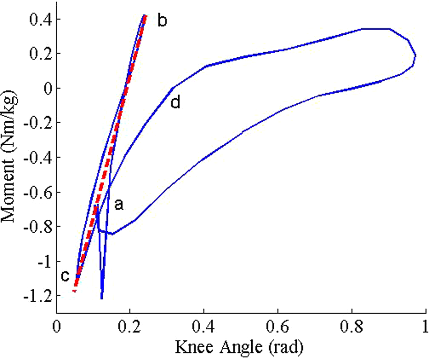
The knee moment–angle (stiffness) graph of one gait cycle.
Contrary to the stance leg, the knee of swing leg displays substantially smaller moments in the rest of gait cycle. The kinetic and potential energy of leg is used to extend the knee joint during swing phase without significant power from muscular activities. During the swing phase, the knee is predominately energetically dissipative, and no obvious linear slop in the moment–angle graph can be identified.
Furthermore, human have the ability to dynamically adjust the stiffness of knee to compensate the changes in gait, ground stiffness, speed, and weight of body. This ability leads to a superior performance in energy efficiency and robustness. 4 Researchers postulate that a device can mimic this compliance behavior of inherent knee using a spring with suitable stiffness in stance phase and disconnecting the spring in swing phase. By adjusting the stiffness of this spring, the knee allows a proper load response and a good adaptation to various load weights, speeds, and terrains. 4
Design and implementation of UVSHA
Design objectives
The actuator design present in this article aims to actuate the knee joint of a field-operational load-carrying exoskeleton. Unlike the lower extremity exoskeletons for rehabilitation that usually dominate motion of joint and propel wearer’s limbs following motion command paths through gait cycle, this kind of exoskeleton is designed to provide external impedance and substitutes for part of the function of joints without disturbing the natural attributes of wearer’s joints. To this end, we envision the following functional and requirements for the actuator design. The actuator should have a fast, reliable, and low-energy demand mechanism to engage/disengage the stance phase control as the change of gait phases. This guarantees the actuator can instantaneously engage/disengage external impedance at the onset and end of the stance phase. The device should free the knee in swing phase so that the exoskeletal leg can easily follow the motions of wearer’s limbs and initiate next stable stance phase. This is beneficial to the realization of passively walking even when the power of exoskeleton is running low. The actuator should be capable of injecting power into the joint and controlling the joint torque with a high fidelity for load carrying and lifting. Researchers postulate that the exoskeleton might totally mimic the dynamics of lower limbs if the normalized joint torques of exoskeleton are equal to wearers.
15
For a 20-kg load-carrying leg exoskeleton designed to carry a weight up to 60 kg over various terrains, the torque capacity should close to those of an 80 kg adult when he is climbing the stairs. This requires a maximum torque of at least 150 N·m. The actuator should be capable of adjusting the knee stiffness of up to 750 N·m/rad for adapting different environmental requirements, which is about the knee stiffness of an 80 kg adult during level walking. To avoid increasing the energy demand for stiffness adjustment, the stiffness adjustment should be no need to directly overcome the whole joint torque or the reactive force of elastic element. This is particularly important when the joint stiffness is required to be adjusted, while the joint torque is especially large. Otherwise, the actuator would fail to adjust the joint stiffness. Essential sensors, such as torque/force sensors for sensing and control, should be embedded in the mechanism of device. This results in a reduced size and dimension of joint without installing extra vulnerable sensors near joint and improves the reliability of whole device. To avoid further increasing the inertia of exoskeletal leg, the weight of components near the knee joint should be as less as possible. A separated arrangement that only remains a light end-effector near the exoskeletal knee joint is recommended.
Comparing to existing electric designs with variable stiffness ability, a high-pressure hydraulic actuator design might be a more suitable alternative for above-mentioned requirements because of its higher power–weight ratio, good controllability, and the flexibility of structure arrangement. The high-pressure small-flow hydraulic system can provide the joint with sufficient power for load carrying and lifting without significantly increasing the weight and bulk of whole system. The joint can also easily achieve near-zero impedance for free swing by bypassing the high-impedance hydraulic components. By taking advantage of hydraulic transmission, a lightweight end-effector, such as hydraulic cylinder or motor, is the only component required to install near the joint without installing the whole devices and sensors. This makes that the whole leg remains light and handy, prevents vulnerable components from accidental damages during locomotion, and is beneficial for the wearer to swing the leg of exoskeleton during swing phase without increasing the metabolic cost of wearer.
Implementation of UVSHA
The prototype of UVSHA is composed of a stiffness adjusting module integrated into a valve-controlled hydraulic system, as shown in Figure 2. As the end-effector of actuator, a single acting hydraulic cylinder mounted in a triangular configuration with the knee joint of exoskeleton, transforms the linear stiffness and output force of hydraulic cylinder to a torsional stiffness and torque around the knee joint. The hydraulic cylinder is connected to the hydraulic manifold and stiffness adjusting module by a tee coupling and flexible tubes. The stiffness adjusting module composed of a leverage with variable lever ratio, controls the linear stiffness of hydraulic cylinder, and finally changes the passive compliance of joint.

Schematic diagram of UVSHA. UVSHA: unidirectional variable stiffness hydraulic actuator.
Hydraulic manifold
The hydraulic circuit in hydraulic manifold describes the ultimate functioning of the system. To realize the locomotion of exoskeleton, the hydraulic circuit of UVSHA achieves three important control states: Inputting appropriate power into the end-effector for powered extension during stair climbing and standing. Isolating end-effector and stiffness adjusting module for mimicking the passive behaviors during stance. Connecting the end-effector directly to the reservoir with minimal resistance for freely swing.
The complete hydraulic circuit of UVSHA is depicted in Figure 3. The major components of this circuit include a servo valve, a pump, a relief valve, a check valve, and pressurized reservoir. The servo valve is in series with the pump and a check valve that protects the pump from unexpected high pressure. This servo valve determines which path/components in the hydraulic circuit are connected and changes the resistance of the fluid motion during torque control.

Hydraulic circuit of UVSHA. UVSHA: unidirectional variable stiffness hydraulic actuator.
This hydraulic circuit allows the electrohydraulic system of UVSHA to employ a semi-active actuation scheme in stance phase. In level walking, the servo valve disconnects the hydraulic cylinder and stiffness adjusting module from the hydraulic system after heel strike until toe-off. The servo valve prevents the fluid flow in the hydraulic cylinder from back to the pump and remains the necessary pressures to support the load in stance phase. In this case, the hydraulic cylinder and stiffness adjusting module constitute a passive spring-like system that makes the joint working as a tensional spring with an appropriate stiffness. Once toe-off, the servo valve fully connects the hydraulic cylinder to the reservoir and allows the joint passively swing with wearer’s limb to completing toe clearance. A secondary use of this circuit is to reduce power consumption during swing extension. Fluid can bypass the pump and back to the cylinder once extension of wearer’s joint is in progress. By constituting a spring-like structure in stance and providing a free swing, the actuator can realize a passive level walking without actively pumping the fluid into the joint. When powered extension/flexion or high-performance fidelity torque control in stance phase is required, the system is in active mode. The extra fluid can be pumped into the joint to compensate pressure loss due to motions and reach certain desired joint torque under the regulation of servo valve.
The three-dimensional (3-D) model of hydraulic manifold is shown in Figure 4. An external gear pump with a fixed displacement about 1.6 cc/rev driven by a customized brushless direct current motor (BLDC) is integrated into the hydraulic manifold. The pump is submerged in the hydraulic fluid, which is contained in a round aluminum shell reservoir. The customized BLDC motor with samarium-cobalt permanent magnetic rotor is capable of providing sufficient power to the joint with a rated output about 375 W and the maximum output up to 1 kW. This BLDC motor rotates with variable velocity to maintain the supply pressure based on a feedback from pressure transmitter (Huba Control, Switzerland, Type 511.941) which is installed next to the check valve. The system normally operates at about 14 MPa with peak pump operating up to 20 MPa. A customized servo valve rated for a maximum of 1.6 L/min is chosen as the main control component of actuator.
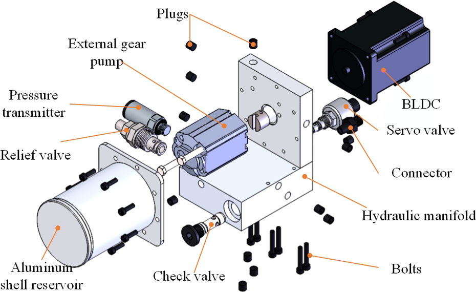
Explosive view of 3-D model of hydraulic manifold. 3-D: three-dimensional.
Stiffness adjusting module of UVSHA
The design of an ideal exoskeleton for load-carrying augmentation should employ a variable stiffness mechanism that allows for increase in the characteristic stiffness of the knee if the weight of wearer or loads is changed. 15 The stiffness adjusting module of UVSHA is responsible for the regulation of passive compliance of joint.
As it can be seen in Figure 5, stiffness adjusting module of UVSHA adopts the concept of variable lever ratio. A small piston connected to the output hydraulic cylinder pushes one side of lever with a constant distance from the pivot. A die spring placed in a mobile base applies a counter force on the other side lever. About 2 mm precompression of spring keeps the spring head cover and the small piston contacting the lever. The mobile base is constrained by the frame of module, which is working as a guide rail to prevent the base from undesired rotating. As a result, the mobile base can only move along the axis direction of lever. Due to the deformation of spring, the lever rotates a small angle when it is loaded. This results in tiny force component parallel to the axis direction of screw. A pair of angular contact ball bearings is used to remove this force component and further reduce the frictional resistances during stiffness regulation.
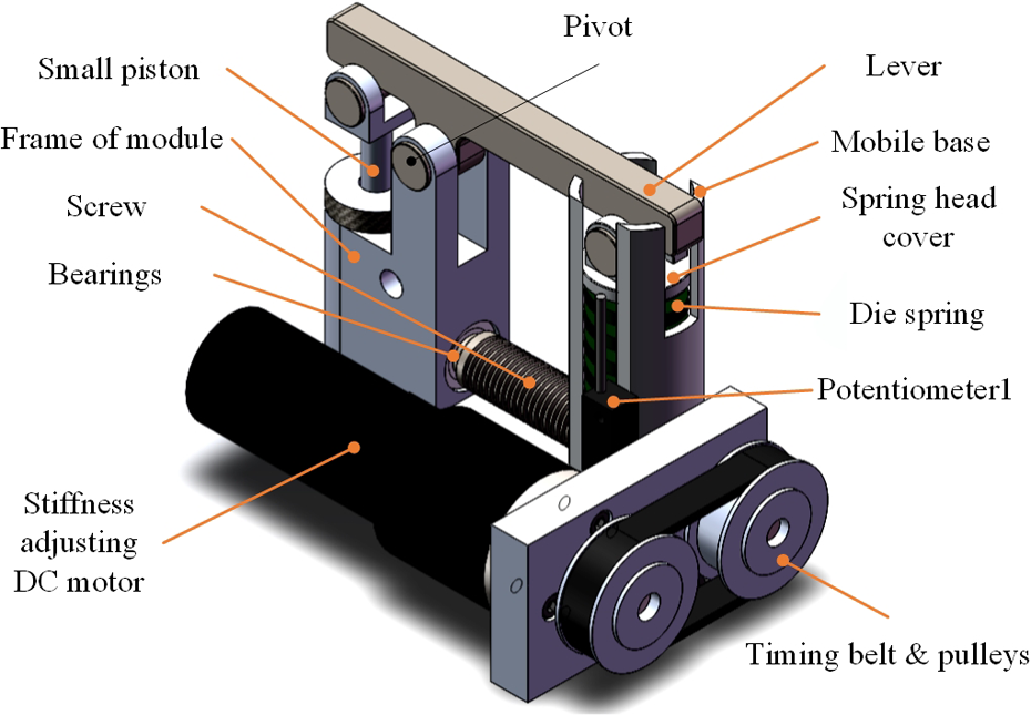
3-D mode of stiffness adjusting module. 3-D: three-dimensional.
Because of the distance between the pivot and the small piston is constant, actually, the regulation of lever ratio is realized by modifying the position of the mobile base. The distance between the pivot and the mobile base can be controlled by the action of the stiffness adjusting DC motor through a synchronous belt transmission and a lead-screw mechanism. The rotation of motor increases or decreases the arm length of spring force and thus varying the proportional relation between the ends of the lever. This process adjusts the equivalent output stiffness of small piston and ultimately changes the overall joint stiffness.
One advantage of this design is that it allows a small-size spring with lower spring rate to be used in the stiffness adjusting module. Since the arm of force from small piston is usually smaller than the arm of spring force, the lever works as an amplifier to magnify the balance spring force. This advantage remains to be stiffness adjusting module compact and avoids the spring being saturation due to the huge output force. The other advantage of this design is that it avoids using nonlinear elastic elements to provide the nonlinear stiffness profile and enhances the accuracy of the stiffness adjustment. Furthermore, when the lever reaches a force equilibrium condition during torque control, the spring force is nearly perpendicular to the axis direction of screw. This avoids counteracting the full amount of the spring force during stiffness adjustment. With the helps from low frictional guide rail and bearings, less amount of effort is required to regulate the stiffness. These advantages allow a small low-power control device to be used in stiffness regulation. A 20-W DC motor with optical encoder (Maxon motor, Switzerland, RE-25 and HEDL 5540) and a planetary reducer (reduction ratio, 14:1) is chosen. The output of reducer is coupled with a low friction lead-screw mechanism (screw lead p: 1 mm/round) through a synchronous belt (transmission ratio, 1).
The hydraulic transmission allows the sensors of UVSHA to be embedded in the stiffness adjusting module. This setup remains a reduced size and dimension of joints without installing extra vulnerable sensors near the joint and improves the reliability of sensing system. Two high-precision linear potentiometers are used to feedback interaction force and stiffness adjusting condition to the controller of UVSHA. One linear potentiometer mounted at the frame of stiffness adjusting module along the axis of screw provides arm of spring force by measuring the displacement of mobile base. And the other one is set on the mobile base along the axis of die spring to measure the changes of spring compression that can be further convert to variation of spring force.
To illustrate the adjustable stiffness mechanism of UVSHA, the schematic of an exoskeletal knee actuated by UVSHA is shown in Figure 6. The stiffness adjusting module is partial enlarged. The unmentioned notations are presented in Table 1.
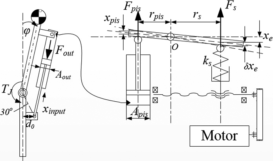
Schematic of stiffness adjusting module in un-equilibrium state.
Notation of UVSHA.

UVSHA: unidirectional variable stiffness hydraulic actuator.
To simplify the model, some assumptions are made. For convenience, the area of small piston Apis is supposed to be as same as that of output hydraulic cylinder Aout. The servo valve of control hydraulic circuit is modeled as a high-impedance flow source. As a consequence, once the path is in state (i) or (ii), the fluid due to the input motion disturbance xin can only enter the small cylinder of stiffness adjusting module and further convert into the compression of spring directly. Thus, the output stiffness of output cylinder Kout depends on the equivalent stiffness of small piston Kpis. Moreover, in stiffness adjusting module, the contacts between lever, small piston, and spring head cover are assumed to be point contact. The forces acting on lever from small piston and spring are assumed to be perpendicular to the stiffness adjusting displacement, neglecting the small component of reactive force paralleling to the stiffness adjust displacement on mobile base.
Assuming certain desired joint toque is achieved, the lever of stiffness adjusting module is balanced at an equilibrium spring compression xe. The displacement of small piston xpis caused by the gravity moment of heavy loads or the voluntary motions of wearer’s limbs results in a variation of equilibrium spring compression δxe and changes the absolute compression of spring xs.
The force acting on small piston Fpis is directly related to the compression of spring and the arm length of spring force by the following equation

where ks is the elastic coefficient of spring, rs corresponds to the arm length of spring force measured by linear potentiometer 1, xs corresponds to the absolute compression of spring measured by linear potentiometer 2, and rpis is the constant arm of Fpis.
According to level principle with variable lever ratio, the equivalent stiffness of small piston Kpis can be described as

where r is the lever ratio and r = rs/rpis.
The joint stiffness KJ is related to the stiffness of output cylinder Kout and the angle of knee ϕ, based on the definition of mechanical impedance, according to the geometry scheme in Figure 6. KJ can be described as follows

where A is the piston area ratio, A = Aout/Apis. By substituting equation (2) into equation (3), the knee joint KJ can be obtained as

Since the interested quasi-passive behavior of knee appears in stance posture when the flexion angle of knee ϕ approaches to zero, formula (4) can be further simplified as

Obviously, the stiffness of knee in stance posture is theoretically irrelevant to the output force of actuator but primarily depends on the adjustable lever ratio r and the elastic coefficient of spring ks. This unique characteristic of lever-type configuration provides a convenience but effective method to adjust the passive compliance of UVSHA.
The lever ratio r creates a proportional influence on the stiffness of joint according to equations (2) and (5). In addition, equations (2) and (5) also imply that a theoretically infinitely high stiffness can be reached for r near 0, if rpis approaches 0.
By changing the arm of spring force rs stiffness of knee, KJ can be adjusted in a quadratic exponential form as the lever ratio changes. For a given desired joint stiffness

where the superscript d indicates that the parameter is a desired value.
Numerical experiments were performed to assess the performance of passive compliance of actuator according to equation (5). For the first prototype designed for a load-carrying knee exoskeleton, the elastic coefficient of die spring is about 163 N/mm, and the available lever ratio ranges from 0.5 to 2.6, respectively. Figure 7 presents the joint stiffness as a function of lever ratio r (0.5–2.6) and the joint angular φ (0–1.8 rad) in a numerical experiment. Adjustable joint stiffness of this design theoretically ranges from about 80 N·m/rad to 1350 N·m/rad. The joint stiffness primarily depends on the lever ratio, with the effect of angular becoming more obvious as the joint angular increases.
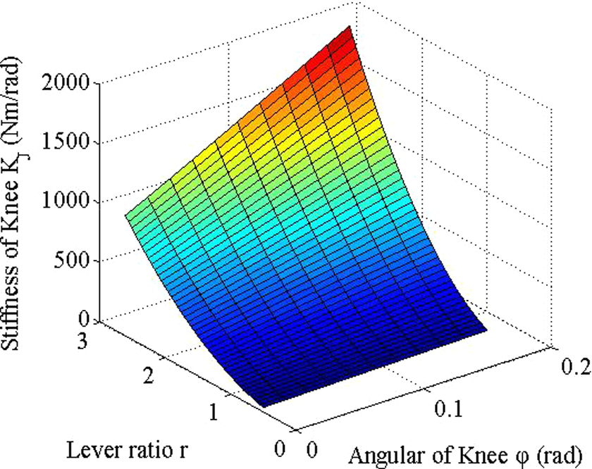
Joint stiffness as a function of lever ratio and the angular of joint in stance posture.
Control of UVSHA
A custom board consists of a dsPIC microcontroller (dsPIC30f6010A) and a 16-bit A/D converter chip (AD7888) is designed to control the exoskeletal knee joint actuated by UVSHA. This controller performs the regulation of the servo valve and stiffness adjusting motor at 1 kHz. A Proportional-Differential (PD) controller is used to control the output force of hydraulic cylinder Fout and finally controls the joint torque by adjusting the opening of servo valve. And another Proportional-Integral (PI) position controller for stiffness adjusting DC motor is performed to control the passive stiffness of actuator. The inputs of controller are the reference output torque

Schematic diagram of control system.
The servo valve is assumed to be a first-order element

where Kc is the gain of controller. Assuming the actuator is imposed with a fixed end and neglecting the motion disturbance xin, the closed-loop dynamic equation of output force can be describe as a second-order system

It is important to note that the equivalent stiffness, Kpis, is a function that depends on the lever ratio r according to equation (2). Therefore, dynamic performance of closed-loop force control would change, if Kpis is changed. Obviously, if Kpis is reduced, the passive compliance of actuator would improve, but the torque control bandwidth would degrade as reduction of overall mechanical stiffness and vice versa. The gain of controller should be tailored to guarantee the dynamic response of active torque control. A convenient and effective method is to keep the gain of forward path being constant. To this end, an inverse model of stiffness adjusting mechanism is used to provide an estimated value of equivalent stiffness
Preliminary experimental evaluations
To evaluate the performance and main characteristics of UVSHA prototype, a number of experiments are performed. These experiments mainly focus on the ability of passive stiffness regulation and torque control performance, including quasi-static condition and dynamic condition.
Stiffness tuning
Initially to examine quasi-static passive compliance of prototype, an exoskeletal knee actuated by UVSHA is set as the schematic for the measurement of characterization of a variable stiffness actuator. 18 One link of joint (thigh) is mounted at a test table and the rotation axis of joint is parallel to ground. This allows the joint flexing to the vertical position freely if no torque is applied to against the gravity moment. Except two potentiometers for the torque measurement, an encoder is temporarily added to measure the angular knee joint. A known initial mass (about 15 kg.) hanged at the end of the other link (shank, about 0.4 m length) is used to apply a load (about 60 N·m) to the joint. First, certain lever ratio is set by the stiffness adjust motor. Because of the interested passive behavior appears when the angular of joint is close to zero, a torque is initially applied on the joint to against the gravity of this initial mass. Once the shank is horizontal, the servo valve isolates hydraulic cylinder and stiffness adjusting module. This is similar to the condition that the joint is in stance phase. By gradually increasing and decreasing the mass at the end of shank, the deflection profile of joint and joint torque for given lever ratio can be obtained. Four trials have been executed with four different lever ratios (1.0, 1.2, 1.5, and 2.6). Figure 9 shows the torque and angle trends for different values of lever ratio. It is clear that by changing the lever ratio, the stiffness of joint can be tuned in a wide range. As the lever ratio increases, the slope of the curves becomes steeper indicating the joint stiffness rise. The maximum experimental stiffness of joint is about 1249.3 N·m/rad when the lever ratio is changed to 2.6.
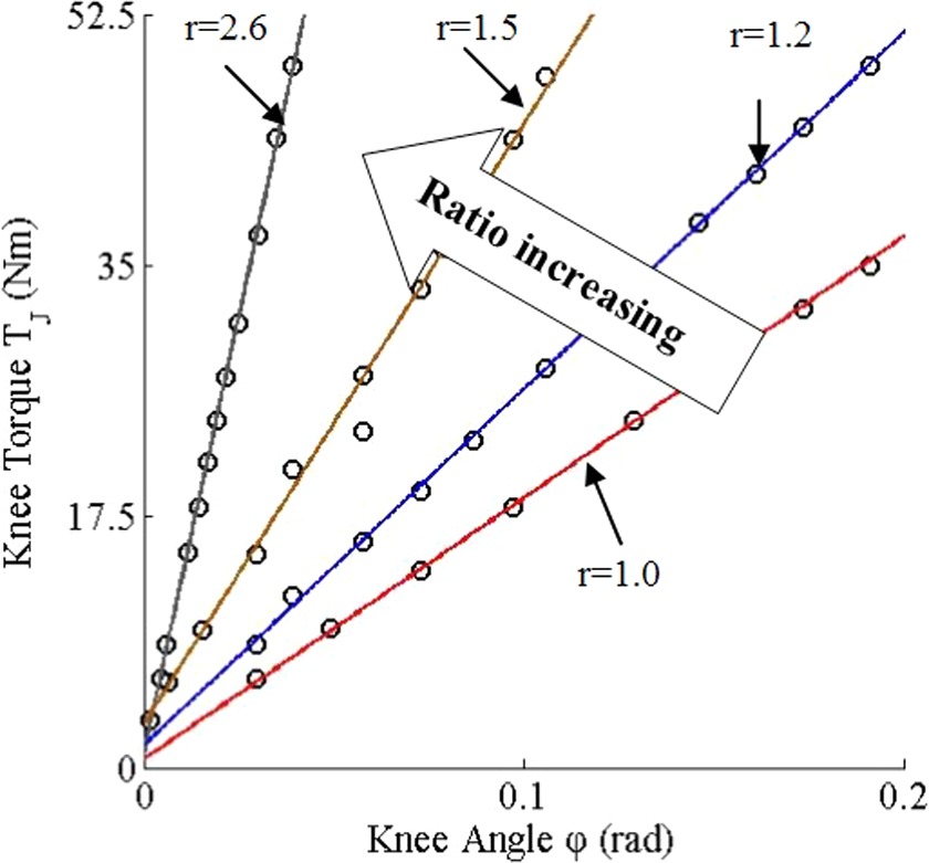
Torque versus joint angle curves for different lever ratios.
Joint torque control
To evaluate the torque control performance of joint and validate the gain-scheduling control method illustrated in Figure 7, three experiments are performed. To eliminate the effect of joint motion, both thigh and shank are fixed in these experiments. In the first experiment, the actuator is ordered to track desired torque trajectories. The joint stiffness is set about 600 N·m/rad that is about the median value of available stiffness range. Figure 10 presents the joint torque trajectory against a sinusoidal reference one at 5 Hz. The mean and amplitude of this reference trajectory are both 60 N·m. It can be observed that the output torque trajectory shows the presence of unsymmetrical hysteresis. This hysteresis is most likely a result of the unidirectional spring-loaded structure and nonlinear characteristic of elastic element. But beyond that, the actuator shows the capability of joint torque control with good fidelity.

Output joint torque tracking a 5 Hz sinusoidal reference curve.
In the second experiment, sweep-frequency signals are sent to the controller for frequency response analysis. Two trails are performed for the minimum and the maximum stiffness value of available range, respectively. The bode diagrams for two typical stiffness values are shown in Figure. 11. It is clear that although the passive stiffness values of actuator in two trails are entirely different, the frequency responses of torque control approach to the designed reference one. This reveals the controller can effectively avoid dramatical degradation of torque control as increase of passive compliance.

Frequency responses of torque control for two different stiffness values.
In the third trial, both servo valve for torque control and DC motor for stiffness regulation are controlled to follow sinusoidal torque and stiffness trajectories of different frequencies, simultaneously. Figure 12 presents the joint torque and stiffness trajectories against the desired ones. This reveals the actuator to control both variables independently with good fidelity.

Tracking a sine wave trajectory: torque (top) and stiffness (bottom).
Knee exoskeleton implementation
Figure 13 shows a knee exoskeleton for load augmentation actuated by UVSHA prototypes was worn by an adult tester in a level walking trail at normal speed (about 2 km/h). The mechanical structure, sensing system, and gait control of exoskeleton were reported in preliminary works. 19,20 In this trail, knee joints work in the passive mode, which is introduced in “Design and implementation of UVSHA” section. The stiffness of knee was auto pre-adjusted to certain value based on the total weight of wearer and preloads measured by the sensing shoes.

Actuator prototype implementation in a knee exoskeleton.
The knee exoskeleton actuated by UVSHA complied with the locomotion of wearer and presented a high robustness during walking. The normalized knee torque and stiffness graphs during this level walking trail are presented in Figures 14 and 15. The data are initially divided into several groups in each step. The average curves of these divided curves are normalized by the payload weight and finally plotted in one gait cycle. The normalized stiffness of exoskeletal knee joint is close to that of biological knee joint in stance phase, revealing the exoskeletal knee performed anticipative passive behavior in level walking without the joint actuators exerting additional torque and the resulting energy consumption.

Normalized exoskeletal knee torque of one gait cycle in a level walking trail.

Normalized exoskeletal knee stiffness in a level walking trail.
Conclusion
In this article, a UVSHA designed for a load-carrying knee exoskeleton was investigated. By introducing a stiffness adjusting mechanism into transmission, a common hydraulic actuator obtains the ability of variable passive stiffness. The decoupled stiffness control is achieved by controlling the location of the springs, thus changing the spring force amplification ratio of level.
The structure of proposed design was introduced and the simplified model was analyzed. Numerical simulations were also carried out to investigate the influence of parameters, including lever ratio and joint angle. A preliminary gain-scheduling PD control algorithm based on an estimated stiffness value is adopted to avoid the degradation of torque control performance due to the dramatic change in stiffness.
Several prototype experiments were carried out to evaluate the performance of proposed design, including passive stiffness regulation performance and torque control performance. The experimental results confirm that the proposed design presents a wide range of stiffness regulation and good fidelity torque control.
The main characteristics of prototype, including peak/constant torque, available range of stiffness regulation, and the bandwidth of torque control, are summarized in Table 2. These values are also compared with the desired specifications for a load-carrying knee exoskeleton. It can be observed that the proposed design features many of the characteristics required for a load-carrying knee exoskeleton. Further, the knee exoskeleton implementation test indicates that the actuator prototypes can improve the passive compliance of joint and reproduce the passive behavior of biological knee in stance phase of level ground walking. This verified the proposed actuator design is capable of actuating the joints of load-carrying knee exoskeleton.
Comparison of existing variable stiffness actuators and desired specifications for load-carrying knee exoskeleton.

UVSHA: unidirectional variable stiffness hydraulic actuator; MACCPEPA: mechanically adjustable compliance and controllable equilibrium position actuator; AwAS: actuator with adjustable stiffness.
Future work should devote to the reduction of unsymmetrical hysteresis appear in torque control, the realization of more compact hydraulic system, and the development of control algorithm.
Footnotes
Declaration of conflicting interests
The author(s) declared no potential conflicts of interest with respect to the research, authorship, and/or publication of this article.
Funding
The author(s) disclosed receipt of the following financial support for the research, authorship and/or publication of this article: This work was supported by National Natural Science Foundation of China (Grant No. 51275170) and Specialized Research Fund for the Doctoral Program of Higher Education (Grant No. 20100074110005).