
Abstract
The planetary gear trains are commonly used in automotive transmissions. A practical method to analyze planetary gear train for speed ratio determination is lever analogy. The classical lever analogy provides an easy way to study the kinematics and determine the power flow of a three- or four-speed automatic transmission. However, the classical approach becomes very complex and not easy to use in analyzing transmissions having three or more planetary gear trains. This article presents a systematical approach of an improved lever analogy method to simplify the analysis. Two higher multi-speed automatic transmissions and several hybrid powertrain transmissions are discussed as examples to demonstrate the determination of speed or torque ratios using the method. The developed technique can be further applied to optimize the designs of component sizing, configuration, and power control of many types of automotive transmissions.
Keywords
Introduction
The planetary gear sets, or epicyclic gear drives, are commonly used to transform torque and speed in many automotive, aerospace, and marine applications. For an example of automotive applications, most automatic transmissions utilize planetary gear sets for torque or speed multiplications. A typical planetary gear set consists of three components (carrier joining all planet gears, ring gear, and sun gear) and each of these three components can be used as the input, output, or kept stationary. Different gear ratios can be achieved by choosing each component to play a different role. In an automotive automatic transmission, clutches and brake are used to hold different components stationary and change the input and output, thus changing the transmission gear ratio for torque or speed multiplications. Compared to the conventional gearbox arrangement, the planetary gear set has many advantages, such as more options for generating ratios, compact space and weight reduction, higher efficiency, and higher load-carrying capacity. 1 The planetary gear set is also a mechanical power-split device for electrically continuous variable transmission (e-CVT or EVT) in the hybrid electric vehicle (HEV), such as Toyota Prius2,3 and Chevrolet Volt. 4
The automotive transmission analysis involves the task of conceptualizing configuration of planetary gear sets, constrained interconnections, clutched interconnections, and input–output connections to achieve a desired set of input–output ratios. A practical method to analyze planetary gear sets is lever analogy that was introduced in 1981. 5 The lever analogy is an analytical method that converts the rotational elements of a planetary gear (carrier, sun, and ring gear) into one single vertical lever. The nodes on the lever represent the elements of planetary gear. The input, output, and reaction speeds and torques are represented by horizontal vectors (forces) applied to the lever. 6 Therefore, the relative rotational speeds of ring, carrier, and sun can be computed by treating rotational speeds as forces acting on the lever nodes, and taking moments about appropriate nodes on the lever. Any 1-degree-of-freedom planetary gear train can be reduced into a single lever to allow easy calculation of torques and speeds. Because the lever analogy is useful and simple representation of driveline kinematic arrangement, it is widely used to analyze automotive automatic transmission, including EVTs. Ahn et al. 7 used lever analogy to determine kinematical maximum speed in performance analysis of a dual-mode EVT. Using the lever analogy, the power flow analysis of series-split EVT in a plug-in hybrid vehicle was performed by Ma et al. 8 S Hong et al. 9 applied lever analogy to derive speed and torque equations in a dual-mode power-split EVT for mode shift analysis. In a proposed multi-mode transmission with single electric machine, 10 the lever analogy was used to analyze transient torques from different power sources.
The classical lever analogy provides an easy way to study the kinematics and determine the power flow of three- or four-speed automatic transmissions. However when analyzing transmissions which contain three or more planetary gear sets (such as five-, six-, seven-, or eight-speed automatic transmission and EVT), the classical approach becomes very complex and not easy to use. This article presents a systematical approach of an improved lever analogy method to simplify the analysis. The six-speed automatic transmission and several EVTs are discussed as examples to show how to determine the speed and torque ratios using the method. The same method can be used to analyze and optimize the speed and torque ratios of any transmissions.
Overview of lever analogy method
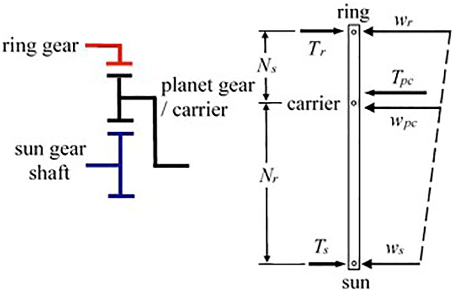
The procedures of establishing a lever analogy system for planetary gear sets were presented in Liao 6 as (1) replace each gear set by a vertical lever; (2) rescale, interconnect, and/or combine levers according to the gear sets’ interconnections; and (3) identify the links of the levers according to the gear sets’ connections. The teeth numbers on the sun and ring gears determine the lever proportional lengths. The layout of a single planetary gear set and its free body diagram is shown Figure 1, where N, r, T, and w represent the teeth number, radius, torque, and angular velocity of gear, respectively.6,11 The subscripts p, pc, s, and r are for planet, planet carrier, sun, and ring gears, respectively. Equation (4) illustrates the torque ratio between sun and ring gears based on equations (1)–(3)


Therefore

The tangential velocity, V, at the contact point between ring and planet gears is

and

Therefore

Using common tangential velocities at sun and planet gears gives

Sum of equations (7) and (8), it gives

Single planetary gear set
The stick diagram of a single planetary gear set and its lever representation is illustrated in Figure 2. The torque on each planetary gear element is derived from equations (10)–(12). It is noted that one known torque can determine other two torques. The relationship of angular velocities is shown in equation (14) indicating it needs two known angular velocities to calculate another one. These torque and speed equations are simplified when one of the planetary gear elements is grounded (or held). Figure 3(a) shows that carrier is held; then the ring and sun gear rotate in opposite directions at relatively speeds inversely proportional to their numbers of teeth. Figure 3(b) shows the lever diagram as sun gear is held. Figure 3(c) shows a compound, or dual-ratio, planetary gear which consists of two sets of planet gears possessing different radii. The larger gear engages a centrally located sun gear, while the smaller gear engages the ring gear. The stepped planet gears enable a larger speed reduction ratio in a more compact geometry than an ordinary planetary gear can provide


Stick diagram and lever representation of a single planetary gear set.

Examples of lever representations of single planetary gear: (a) carrier is held, (b) sun gear is held, and (c) a compound planetary gear set and its lever diagram.
Multiple connected planetary gear sets
When analyzing two or more connected planetary gear sets, each planetary gear is replaced by one vertical lever and the interconnections between planetary sets are represented by straight links connected to the appropriate points on the levers. One important procedure is to determine the relative scale factor and placement of each lever for multiple connected planetary gear sets. In many cases, one solo lever having the proportionally vertical dimension between points can functionally replace multiple connected planetary gear sets. Figure 4 illustrates an example of two connected simple planetary gear sets, their schematic diagrams and levers representations, and the process of combining two levers. Nr1 and Ns1 (Nr2 and Ns2) are teeth numbers for ring and sun gear at planetary gear 1 (planetary gear 2), respectively. Figure 5 shows the Ravigneaux gear train, a combination of one simple and one compound planetary gear set, which has dual sun and planet gear sets with a single ring and common carrier holding two planetary gear sets. The Ravigneaux gear train, commonly used in automotive automatic transmission, has two sun gears that are co-axial and longitudinally separated along the rotational axis. The smaller sun gear engages the inner planet gears which then engage outer planet gears. The outer planet gear set having length spans the distance to engage both the larger sun gear and ring gear.
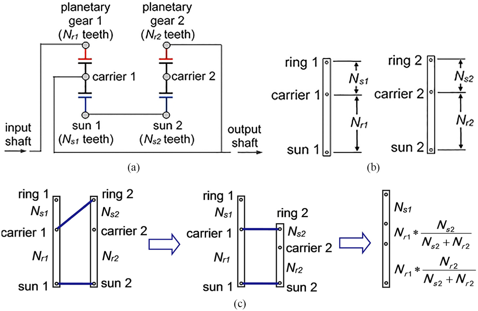
Example of two connected gear sets and lever representations: (a) a schematic diagram of two connected planetary gear sets, (b) lever representation of each gear set, and (c) combining of two lever representations.

Ravigneaux gear train and lever representation.
Applications of lever analogy in transmissions
Most of the automotive automatic transmissions utilize planetary gear sets to attain a number of desired speed ratios. The number of speed ratios is governed by the kinematic structures of planetary gear sets and activating sequences of corresponding clutches. With lever analogy method, an entire transmission is usually represented by a single lever, and the determination of power flow of the four- or five-speed automatic transmissions is simple. However, when designing a transmission with six-speed or more, the approach becomes difficult to use.
Examples of four-, five-, and six-speed automatic transmissions
Figure 6(a) shows a four-speed automatic transmission with two planetary gear sets, two brakes and three clutches. The process of creating lever diagram is illustrated in Figure 6(b). With the teeth numbers are 28, 62, 16, and 80 for Ns1, Nr1, Ns2, and Nr2, respectively, the lever diagram and gear ratio is shown in Figure 6(c). When the clutch Cud and break B1 are applied, the first gear is operated at 2.84 speed reduction gear ratio. The second gear ratio is 1.57 as clutch Cud and brake B2 are applied. The direct drive is at third gear with 1.0 ratio where clutches Cod and Cud are applied. The fourth-gear ratio is 0.69 with the clutch Cod and brake B2 are active. The schematic diagram of a five-speed automatic transmission with three planetary gear sets and corresponding level diagram is depicted in Figure 7(a). The process of combining three lever diagrams into single one is illustrated in Figure 7(b). The schematic diagram of a Volkswagen’s six-speed automatic transmission 12 with one simple and one Ravigneaux planetary gear sets and corresponding level diagram is depicted in Figure 8. Table 1 illustrates the operation of clutch/brake, lever analogy, and gear ratio of each gear in this six-speed automatic transmission.

Lever method for a four-speed automatic transmission: (a) schematic diagram of a typical four-speed automatic transmission, (b) lever diagrams, and (c) lever diagram and gear ratio for the first-gear and fourth-gear operations.

Lever method for a five-speed automatic transmission: (a) schematic and level diagrams of a five-speed automatic transmission and (b) process of establishing lever diagram.

Schematic and level diagrams of a six-speed automatic transmission: (a) Volkswagen six-speed automatic transmission and its schematic diagram 12 and (b) level analogy diagram.
Lever analogy and gear ratio of each gear in six-speed automatic transmission.

EVT
The lever analogy can also be applied for speed analyses in several types of EVTs implemented in production HEVs. Through mechanical connections, the hybrid powertrain controller manages the engine mechanical power to three possible forms: constant rotational speed with increasing torque, constant torque with increasing rotational speed at the vehicle wheels or electricity (thru generator). 13 In the EVT, the continuously variable speed of transmission output shaft is achieved by controlling the electricity supplied to electric motor. The types of EVTs can be classified into input, output, and compound split depending on the location of the power-split device.
The simplest configuration of the EVT is one-mode input-split type that has only one simple planetary gear set and two electric machines, which are all packaged in the transmission housing connected to the engine. A classic example of the one-mode input-split EVT is typically implemented in the first generation (1997–2003) of Toyota Prius or any of Toyota’s Hybrid Synergy Drive vehicles.14,15 The “mode” means the continuously variable gear ratios, so a one-mode EVT indicates this EVT has continuously variable gear ratios within “one” specific speed range which normally is at lower-speed range. Figure 9(a) illustrates the connections of propulsion components with one planetary gear set. The portion of engine torque transmitted and split to the sun gear (MG1) and ring gear (MG2) is dependent upon the ratio of the sun gear to ring gear, Ns/Nr, which is fixed by their teeth numbers. Thus, the portion of the engine power transmitted to the sun gear and ring gear also is determined by the speeds of these gears. The MG2 (traction motor) is used to complement the torque required by vehicle wheels and MG1 (generator) is utilized to regulate the wheel speed.

Toyota EVTs and corresponding lever diagrams: (a) the first generation of input-split, one-mode EVT and (b) the third generation of input-split EVT.
The Toyota’s second-generation EVT (2004 model year) has the same architecture as the original one except larger electric machines. Figure 9(b) shows the third-generation Toyota’s EVT (released in year 2010) and its corresponding lever diagram. The structure of this EVT has two planetary gear sets where the engine drives the carrier 1, MG1 and MG2 connect to sun gear S1 and S2, respectively, two ring gears are on a common output shaft, and the planetary carrier 2 is constrained to the transmission housing. A linear relation exists between the speed of MG2 and vehicle speed due to that MG2 is directly coupled to the output shaft through the second planetary gear set. 16 The speed equation of the first and third generation of input-split EVT is shown in equations (15) and (16), respectively. For a desired engine speed, the speed of MG1 in the third-generation EVT is lower than that in the original EVT


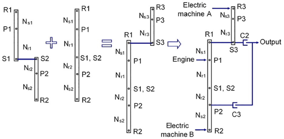
The one-mode input-split EVTs have two drawbacks: (1) the maximum output speed is mainly restricted by the speed of the smaller electric machine (MG1 usually functioning as a generator) and (2) the transmission efficiency (of the transmission alone) drops below that of a generic automatic transmission, especially in higher-speed regimes. The first drawback is due to straight mechanical connection with an electric machine that has its speed limits. The second shortcoming is due to two stages of energy conversions to meet the larger power demand in high speed driving, converting engine mechanical power to electricity by MG1, and then converting electricity to mechanical power by MG2. To overcome these shortcomings of the one-mode input-split EVTs, various types of multiple-mode system have been developed. With additional planetary gear sets and clutches, the multiple-mode EVTs are able to switch the percentage of mechanically or electrically transmitted power. Figure 10 shows an example of two-mode EVT consisting of three planetary gear sets, three clutches, and three power sources (engine and two electric machines).6,17 The engine drives this EVT through a clutch (C1) whose on/off status will allow the EVT to perform in a hybrid or purely electrical manner. Both the shaft of ring gear R1 (in planetary gear set 1) and sun gear S3 (in planetary gear set 3) are connected to the transmission output shaft through clutch C2. Additionally, the planet carrier shaft P2 (in planetary gear set 2) is on the transmission output shaft through clutch C3. In addition to “one” mode for lower-speed range, a two-mode EVT has one more mode for higher-speed range.

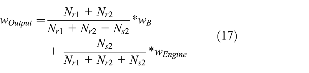
The lever diagram shown in Figure 11 was derived by Liao. 6 During low vehicle speed and less road load, the first-mode effects where C1 and C3 are engaged (with C2 disengaged) such that the engine drives the output shaft using planetary gear sets 1 and 2. The electric machine B, serving as a traction motor, also delivers additional power to the output shaft by planetary gear set 2 and C3. The planetary gear set 3 functions as gear train and part of the engine power, through the ring gear R3, simultaneously drives the electric machine A that serves as a generator to convert mechanical energy to electrical energy for battery recharging. The second mode takes place in high vehicle speed and large road load. With C1 and C2 engaged and C3 disengaged, the engine drives the output shaft via planetary gear sets 1 and 3. The electric machine A becomes a traction motor delivering additional power to the output shaft through planetary gear set 3 and C2. The electric machine B could be in generating or motoring phase based on the driving conditions. The electric machine B acts as a generator which is driven by a portion of the engine power through ring gear R2. During higher road load condition, the electric machine B serves as a traction motor driving the output shaft for torque complement. The level diagrams for these two modes are illustrated in Figure 12. The output shaft speed in the first and second mode is derived in equations (17) and (18), respectively

Lever diagram of two-mode EVT.

Speed diagram of two-mode EVT.
To package the two-mode EVT in a front-wheel-drive vehicle, the housing size of the EVT needs to be scaled down using two or one planetary gear set due to the constrained space of engine compartment. Figure 13 shows a two-mode EVT consisting of one planetary gear set, two clutches, and one brake, which is implemented in Chevrolet Volt. 18 This is an output-split EVT meaning the engine power split at the transmission output shaft. The clutch C2 connects engine and electric machine MG1 that is linked to the ring gear through clutch C1. In this planetary gear set, ring gear connects to brake B1, sun gear ties with the electric machine MG2, and the carrier connects to the vehicle’s final-drive gear. This configuration allows both MG1 and MG2 providing tractive effort while simultaneously reducing electric motor speeds and the total associated electric motor losses.19,20 Controlling the on–off (engaged-disengaged) status of clutches and brake, four operating conditions are available: (1) the first-mode, pure electric vehicle driven by MG2 at low road load, (2) the second-mode, pure electric vehicle driven by MG1 and MG2 at high road load, (3) series hybrid driven by MG2 with MG1 as a generator powered by engine, and (4) output split or parallel hybrid driven by both engine and MG2. The operating conditions and corresponding status of the clutches and brake are illustrated in Figure 13(a). The clutch C2 and engine are off in two continuously variable speed modes where the battery is the only power source for vehicle propulsion. The battery charging status is in depleting operation in two continuously variable speed modes because the clutch C2 and engine are off. The clutch C2 is on and engine runs for the series and parallel hybrids. Such that the engine becomes a main power source to propel vehicle and maintain the battery state of charge in the charge-sustaining operation. The lever analogy diagrams of these four driving conditions are shown in Figure 13(b)–(e). The speed equations of these four driving conditions are illustrated as


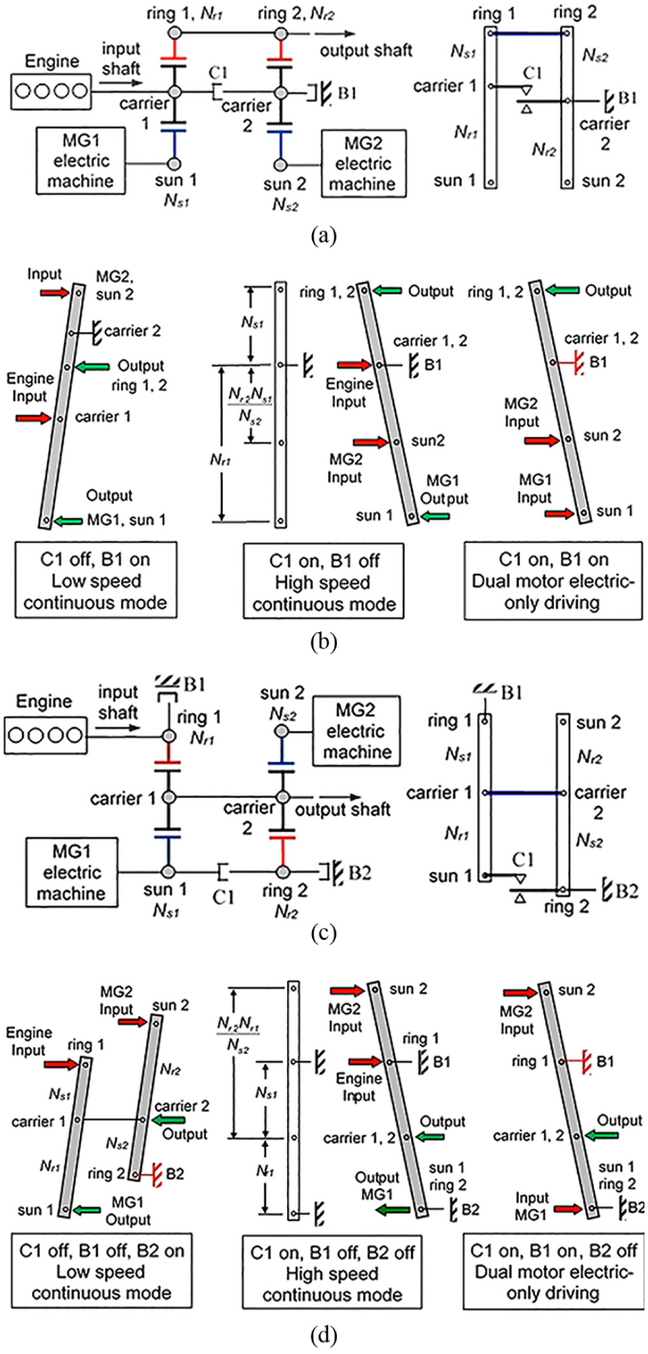
Two-mode EVT with single planetary gear set: 19 (a) schematics and operation conditions, (b) the first mode, (c) the second mode, (d) series hybrid operation, and (e) parallel hybrid or output-split operation.
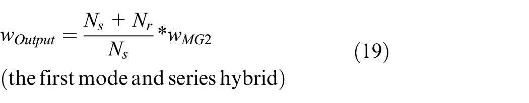
To improve efficiency at higher vehicle speed, the industry trends of the two-mode EVT for a front-wheel-drive vehicle is using two planetary gear sets that are tied together and linked to the transmission output shaft. The 2015 Toyota’s U.S. patent 2015000512521,22 and The 2016 Chevrolet Volt and Malibu Hybrid22,23 demonstrate this type of configuration, respectively, as shown in Figure 14(a) and (c). Toyota connects two ring gears together to the output shaft while Volt ties the planetary carriers. Previous Toyota’s EVT has no clutch while the new design adds one clutch and one brake in its third-generation EVT to support the original lower-speed continuously variable mode plus a higher-speed mode and a dual-motor electric-only (engine off) driving. The continuously variable mode for low speed occurs when the clutch C1 is off and brake B1 is on. The corresponding level diagram is the same as one shown in Figure 9(b). The second mode or higher-speed continuously variable mode is available when the clutch C1 is on and brake B1 is off. The dual-motor for pure electric driving is in the condition that both C1 and B1 are on. The corresponding level diagrams for these three driving conditions are shown in Figure 14(b). Equations (22)–(24) is the speed equation for continuously variable low speed, high speed, and dual-motor electric driving, respectively. The 2016 Chevrolet Volt has the similar architecture and features and its lever diagram is shown in Figure 14(d). Equations (25)–(27) is the speed equation for continuously variable low speed, high speed, and dual-motor electric driving in 2016 Chevrolet Volt, respectively


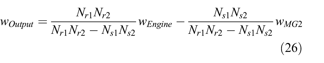

Equations (24) and (27) give the transmission output shaft speed in dual-motor electric driving, respectively, for Toyota’s patent and year 2016 Volt. Assuming both EVTs use the same planetary gear sets, equation (28) gives the result of comparing equations (24) and (27), or equation (24) subtracting equation (27)

If the electric machine MG1 and MG2 operate at the same speed, equation (28) is simplified as
Summary
The lever analogy is a practical tool to analyze power flows and determine gear ratios (i.e. speed and torque ratios) of automotive transmissions using planetary gear sets. However, the lever analogy method does not consider dynamic effects such as gearing friction, clutch transitional phase, transmission fluid viscosity which might affect output speeds and torques. It is also difficult to apply the method in analyzing transmission with more than four planetary gear sets, such as eight-speed automatic transmission. This article presents a systematical approach of an improved lever analogy method to simplify the analysis. The four-, five-, and six-speed automatic transmissions commonly used in passenger vehicles are discussed as examples to demonstrate the determination of speed ratios using the method. The method is also demonstrated for speed analyses in input-, output-, and compound-split EVTs that are equipped in the popular Toyota Prius and Chevrolet Volt HEVs. Using the lever analogy method in analyzing multi-mode EVTs could be the novelty and significance of the work. The methodology and procedure described in this article can become a miniature “cookbook” of levers for various planetary arrangements. The procedure is summarized as follows: (1) replacing planetary gear sets with their equivalent levers; (2) rescaling the levers such that their interconnections are horizontal; (3) combining levers if possible; (4) identifying inputs, outputs, and reaction for each gear; and (5) solving lever system for angular speeds and torques, respectively. The developed technique can be further applied to optimize the designs of component sizing, configuration, and power control of many types of automotive transmissions.
Footnotes
Academic Editor: Xiaoyuan Zhu
Declaration of conflicting interests
The author(s) declared no potential conflicts of interest with respect to the research, authorship, and/or publication of this article.
Funding
The author(s) received no financial support for the research, authorship, and/or publication of this article.