
Abstract
In this article, we present a new three-dimensional printing inspired method for in situ fabrication of mobile magnetic microrobots with complex topology by bending a polymer filament on demand directly inside an enclosed operational environment. Compared with current microrobot fabrication methods that typically involve multiple microfabrication steps and complex equipment, the proposed method is simply and fast. The target shape is formed as the filament is fed through a hot needle inserted into the workspace, and the filament bending moment is induced by attaching a tip magnet at the end of the filament and projecting magnetic fields wirelessly from external electromagnetic coils. The filament bending mechanics and the behavior of the bending zone are analyzed and verified through bending experiment. A shape planner is developed for automatically controlling the fabrication process of any desired planar shapes, and the shape creation potential of this method is also studied. Magnetically active millimeter-scale robotic devices of different planar shapes are fabricated using polylactic acid filament with diameter as small as 100 μm. As demonstrations of the in situ formation of functional microrobotic devices, a micro-gripper is fabricated and controlled to assemble a cell cage. A micro-spring is created as a manipulating tool with force sensing capability. We, thus, show the utility of the fabrication method for creating complex microrobot shapes remotely in enclosed environments for advanced microrobotic applications, with the potential for scaled down applications in health care and microfluidics.
Introduction
The study of mobile magnetic robotic devices at millimeter and smaller scale has attracted recent interest due to their great potential in health care and micromanipulation. 1 In particular, magnetic mobile microrobots are studied most due to the ability of magnetic field to penetrate most materials, thus magnetic microrobots can be controlled wirelessly in inaccessible spaces. 2 The functionality of microrobots in many cases depends on their shapes, for example, force sensing microrobots are usually spring shaped, helical microrobots are used as swimmers, and mobile micro-grippers are typically symmetrical with multiple arms. Therefore, a major task in this field is the fabrication of microrobots of different shapes. Currently, microrobots are predominantly fabricated using micromachining methods borrowed from the microelectromechanical systems community. 2 Thus, many microrobot designs have been limited to simple planar shapes, which are easily defined by photolithography and other pattern transfer methods. 3 –5 The fabrication of more sophisticated microrobotic structures usually requires multistep micromachining process. Through multistep photolithography and electroplating, Frutiger et al. 6 showed a resonant magnetic micro-agent that contains a moving spring element and patterned magnetic material for motion and onboard tool use. A micro-force sensing mobile microrobot was fabricated from three different materials in a process of multistep photolithography, silicon micromachining, and subsequent assembly. 7
Due to the lack of suitable fabrication methods, the fabrication of three-dimensional (3-D) microrobots is more challenging. 8 Especially, the repeatability of the fabrication process and the design parameters are difficult to control. 1 A number of methods have been reported for fabricating helical micro-swimmers as a promising tool for biomedical application. 1 Helical micro-swimmers around 1 mm in diameter and 5 mm long are fabricated from nitinol tubing using micro-wire electrical discharge machining by synchronizing the linear motion with the rotational motion of the cutting wire. 9 Based on a self-scrolling technique, Zhang et al. 10 fabricated the artificial bacterial flagella with a helical tail of 47 μm in length. A shadow growth method known as glancing angle deposition is used in the study by Ghosh and Fischer 11 to fabricate silicon dioxide nanostructured helices of 1–2 μm long. Schuerle et al. 12 reported that helical lipidic microstructures with 0.5 μm in diameter and a few to several hundreds of micrometers in length are made from liposome. As an emerging and promising method for defining 3-D shapes, microstereolithography has been used to make arbitrary 3-D microrobots. Using polymer material and multiphoton lithography, the helical microrobot with a microholder at one end 13 and the porous microrobot for cell culture and transportation 14 are fabricated. A magnetically modified photocurable polymer for microstereolithography is reported in the study by Kobayashi and Ikuta 15 for the fabrication of arbitrary 3-D magnetic microstructures. All these fabrication methods require complex process and expensive equipment.
Most microrobotic applications involve deployment into confined spaces with limited access holes such as microfluidic channels and human body. The deployment may commonly be done using a hypodermic needle 16,17 ; however, the dimension of the microrobots will thus be limited to the size of the access hole or the needle gauge, resulting in overly simple and thin small geometries.
A potential solution for deploying a larger scale robot through a small access hole is to use shape-programmable matters that take advantage of self-folding or self-assembly mechanism. There have been such shape-programmable self-folding robots 18 –22 composed of multiple identical units and can be controlled to change its shape by self-folding. Thus, they can be deployed into inaccessible spaces through a little hole at their original chain shape and self-fold themselves into their functioning shape once inside the space. Self-assembling modular robots 23 –26 can achieve the same function by injecting each module into a workspace one by one and then assembling themselves into a desired shape. However, most self-folding and self- assembling robots require onboard power and controller for their final configuration, 19,20,25 making them unavailable at microscale. For those that no onboard power and controller are required, their self-assembly usually depends on their response to the change in physical conditions such as tempeature 26 or magnetic field. 18,21 This doesn’t guarantee that they can be made at microscale and their response to the changes can be slow. In addition, the shape resolution of programmable matters is limited by the dimension of each identical unit.
In order to reduce the complexity of current microrobot fabrication methods, as well as to eliminate the microrobot size limitation introduced by the access hole, we thus propose a new method for fabricating microrobots with complex shapes in situ using filament of thermoplastic materials in a simple and rapid process. With the initial idea borrowed from fused filament-based 3-D printing, the microrobot can be fabricated in situ by bending a straight polymer filament as it is fed through a needle that is inserted into the workspace. Like the shape-programmable matter, the fabrication process transforms a straight filament into a desired wireframe shape through the little access hole, thus the fabrication process can be performed directly inside the inaccessible workspace. The overall dimension of the formed microrobot is no longer limited by the size of the access hole, and no further transportation process of the microrobot is required. Almost any arbitrary wireframe shapes can be created except for some minor limitations.
In this article, the fabrication concept is first introduced, followed by an in-depth study into the mechanics of filament bending during fabrication. The behavior of the deformation region and bending accuracy are also presented with heat transfer simulation. Then, a magnet angle planner for automatic control of the fabrication process of two-dimensional shapes and the shape creation potential of this fabrication method is introduced. Filament bending experiments are conducted to investigate the properties of the filament material used in the fabrication and to verify the developed theoretical models. In the results, we show the fabrication of several complicated microrobotic shapes using 100–120 μm polylactic acid (PLA) filament with high fabrication accuracy and demonstrate the removal of a fabricated microrobot from its confined workspace. To demonstrate the application of this fabrication method, a micro-gripper is formed inside an enclosed workspace and controlled to perform a sophisticated assembly experiment. A micro-spring is also created to perform a stiffness calibration experiment. We, thus, show the in situ formation of functional microrobots for complicated applications in constrained inaccessible spaces.
Fabrication concept
In this section, we introduce the new concept of magnetically mediated injectable microrobot fabrication. In this method, the microrobot is fabricated by bending a polymer filament into a desired shape as it is fed through a needle that has been injected into the workspace. This method has similarities with a fused filament-based 3-D printing system, 27 where a thermoplastic polymer filament is extruded from a hot moving needle and hardens as it emerges. However, in our case, the needle is stationary, and the formed filament shape rotates itself to create the target microrobot. Shown conceptually in Figure 1, a small tip magnet is first attached to one end of the polymer filament. As a needle is injected into the workspace, the filament can be inserted into the workspace through the needle. Heating wire is wrapped around the needle to soften the filament and magnetic fields are applied around the workspace, thus as the filament is fed through the heated needle, the tip magnet at the end of the filament will respond to an applied magnetic field and induce a torque on the filament tip to rotate the filament structure inside the workspace at the tip of the needle. The magnetic fields are generated by electromagnetic coils outside the workspace, and the use of magnetic fields allows the actuating coils to generate a magnetic torque on the tip of the filament in a wireless, safe, and controllable manner. Since the rotation of the filament structure inside the workspace is induced by plastic deformation in the heated filament at the region immediately past the tip of the needle, and the filament cools down as it is fed through the needle, the filament structure inside the workspace can thus retain its shape and is treated as a formed rigid structure of the microrobot. The needle should be heated up to the glass transition temperature (Tg ) of the filament material to sufficiently soften the filament but lower than its melting point to avoid the filament from melting. Plastic deformation will happen at the small region of the filament where its temperature is above its Tg at the tip of the needle, which we term the plastic deformation zone (PDZ). If the PDZ is small enough, the bending of the filament can be treated as a rotation of the formed structure pivoting the PDZ.

The concept schematic of fabricating a gripper-shaped microrobot with two magnet tips at both of its ends in a confined environment. The fabricated micro-gripper can then be controlled to perform manipulation on micro-objects inside the environment.
More topics covering the details of the filament bending and the PDZ are studied and discussed in the following section.
Modeling and characterization
In this section, the fundamental theories of the bending are first studied, where we introduce the bending methods for getting sharp bends and continuous bends on the filament, and the mechanics model of filament bending under magnetic influences. Then, the effect of different conditions on the length and deformation of PDZ is studied. A magnet angle planner for the automatic control of the fabrication process is introduced, and the limit on the shape creation potential of this method is also explored.
Bending mechanics
Two types of bending: Discrete and continuous
In the mechanics of filament bending, the bending moment is provided by the magnetic torque induced on the tip magnet at the end of the filament. Given a tip magnet with magnetic moment

The torque acts to align the magnet with the applied field and is at the maximum value when the applied field is perpendicular to the magnetization direction. However, due to the cross product in equation (1), no torque can be generated about the magnetization axis of the tip magnet, which will result in a limitation in fabricating 3-D shapes.
For a microrobot fabricated from a filament segment, we introduce two fundamental shape elements, the sharp bend and the continuous bend, which can be fabricated by two types of bending controls developed here, the discrete bending and the continuous bending.
In the discrete bending case, shown in Figure 2(a), the filament is first fed through the needle for a desired length L 2 at a temperature lower than Tg , then the needle is heated to above Tg and a magnetic field is applied to bend the filament by a desired angle α. As the needle cools down, the magnetic field is still applied to maintain the bending angle until the temperature drops below Tg . Thus, a discrete bend with bending angle α is attained on the filament.
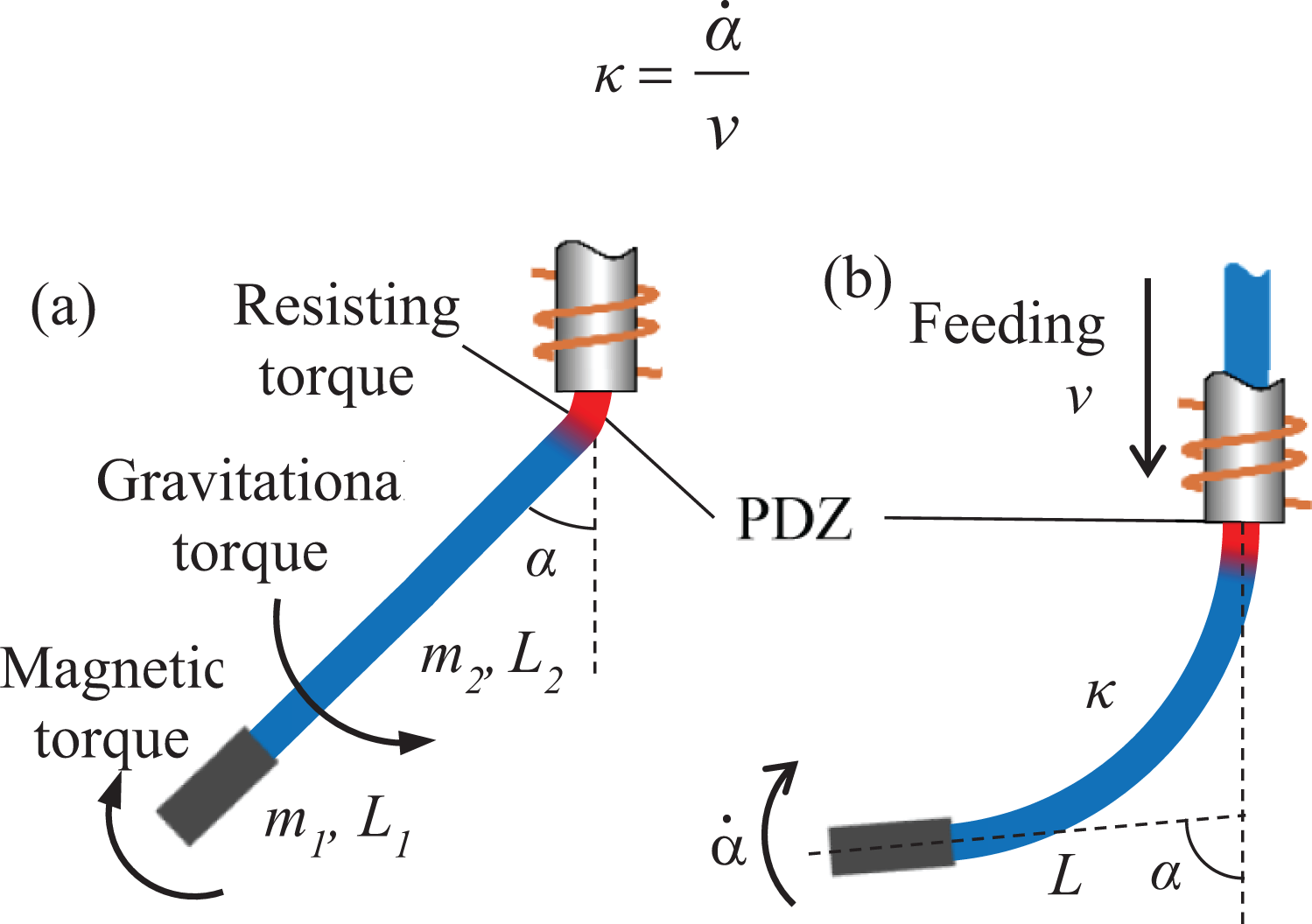
Bending mechanics of (a) discrete bending and (b) continuous bending.
The continuous bending is developed to induce continuous deformation along the length of the filament. As it is a continuous case of discrete bending, the feeding of the filament and the changing of the bending angle should happen simultaneously. Thus, the needle should be heated above Tg
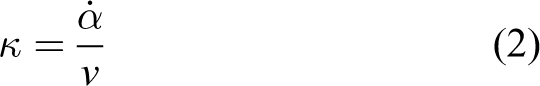
throughout the continuous bending. Here, we use the magnet angle to represent the bending angle α, and thus at any given time, the curvature κ at the point being fabricated is dictated by the changing rate
The mechanics of the bending is mainly governed by the magnitude of the applied magnetic field, the magnetic moment of the tip magnet, and the gravity of the tip magnet, as shown in Figure 2(a). Thus, the bending angle α can be approximated from torque balance as

where

where M is the volume magnetization of the magnet, B is the magnitude of the applied magnetic field, ρ is the density of the magnet, m 1 and L 1 are the mass and length of the magnet, m 2 and L 2 are the mass and length of the filament, and g is the gravitational acceleration. Thus, it can be seen that by increasing the mass of tip magnet m 1 and decreasing the length of the tip magnet L 1, the bending angle will increase. However, as m 1 approaches +∞ and L 1 approaches 0+, α is always smaller than arctan MB/ρgL2, which depicts the maximum bending angle of a filament regardless of the size of the tip magnet.
Study of PDZ and bending accuracy
By assuming that there is no gap between the filament and the wall of the needle, when the needle is heated up and a magnetic torque is applied to the tip magnet of the filament, the filament inside the needle will not deform and plastic deformation will happen along the filament from the tip of the needle to some distance away outside the needle. This part of the filament is defined as the PDZ and its length l PDZ. This indicates that l PDZ will affect the sharpness and accuracy of a discrete bend. As shown in Figure 3(a), considering the thickness of the filament, an ideal discrete bend will have a sharp vertex at the inner side of the bend and an arced outer boundary. In this case, the l PDZ is Dα/2, where D is the diameter of the filament, and thus the minimal bending radius is the radius of the filament. When l PDZ is smaller than this value, the ideal discrete bend can also be achieved when the heated filament inside the needle is stretched by the magnetic torque to compensate for the smaller l PDZ. However, when the l PDZ is larger than Dα/2, as shown in Figure 3(b), both the inner and outer sides of the bent filament will be arced, the radius of the bent part is l PDZ/α.

The illustration of (a) an ideal discrete bend, (b) a discrete bend when l PDZ > Dα/2, and (c) a discrete bend when there is a gap between the wall of the needle and the filament.
In the case where the needle inner diameter is larger than the filament diameter, there will be a gap between the filament and the wall of the needle. When the needle is heated and a bending moment is applied to the filament, the gap will allow for filament deformation inside the lumen of the needle, as shown in Figure 3(c). Unlike cases where there is no gap between the needle wall and the filament, the PDZ will extend into the needle, causing the l PDZ difficult to model and predict. The bending angle will also be affected as the filament inside the needle is no longer aligned with the central axis of the needle.
For thermoplastic material, plastic deformation will happen when its temperature is above the Tg , thus we can define l PDZ as the length of the filament from the tip of the needle to the point where the temperature just drops to Tg . Therefore, to estimate l PDZ under different conditions and study their effect on the bending accuracy, it is essential to simulate the heat transfer along the filament.
The heat transfer along the filament is dominated by heat conduction, while the heat transfer at the interface of filament and the surrounding environment is dominated by heat convection. By assuming the temperature across a cross section of the filament is constant, we can thus model the heat transfer using the one-dimensional model 28

where u(x, t) is the temperature on the filament distance x away from the tip of the needle at time t and u env is the environment temperature and is assumed to be constant. The coefficients a and b are given as
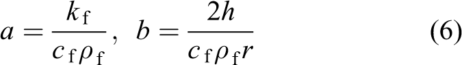
where k f, c f, and ρ f are the thermal conductivity, the specific heat capacity, and the density of the filament material, respectively, h is the convective heat transfer coefficient of free air, and r is the radius of the filament.
The convection between the filament and the environment is subject to many factors, especially to the orientation, length, and structure of the filament. However, during the fabrication, the orientation of the filament changes with the bending and the structure gets more complicated as more bends are induced along the filament. Thus, the convective heat transfer coefficient h also changes dynamically with the fabrication process, and it is difficult to estimate using one single model. To simplify the estimation of h, we assume the filament to be horizontal and infinitely long as the worst-case scenario. The convective heat transfer coefficient h is calculated using h = Nu ⋅ k0/D, and the Nusselt number Nu can be evaluated using the empirical correlation 28
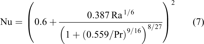
where Pr, Gr, and Ra are the Prandtl number, Grashof number, and Rayleigh number in the free convection, respectively. As the vertical fluid flow induced by the temperature difference between the filament and environment is maximized when the filament is horizontal, the horizontal filament assumption will yield the maximum convection efficiency, thus the simulated length of PDZ is the minimum value. By assuming the filament to be infinitely long, the simulation results are valid only when the equilibrium temperature at the end of a filament is at environment temperature level, where there is almost no heat transfer and negligible end effect.
The boundary condition and initial conditions for the thermal problem are given as

where u needle is the constant needle temperature.
The heat transfer simulation results under different conditions are shown in Figure 4. We can tell that the heat transfer equilibrium will be reached within 1–2 s and the final l PDZ is at the same order of magnitude as the filament diameter, suggesting sharp and accurate discrete bends when needles that match the filament size are used. This also suggests that the simulation results will not be affected by the infinitely long filament assumption when the filament length is longer than 0.8 mm for a 120 μm diameter PLA filament. When the fabrication is performed in a liquid environment, the l PDZ will be even shorter as heat convection in liquid is more efficient than in air. Increasing the needle temperature or the environment temperature will both increase the l PDZ. The l PDZ is more sensitive to environment temperature, while the needle temperature only affects the l PDZ linearly and will not affect the magnitude of l PDZ.
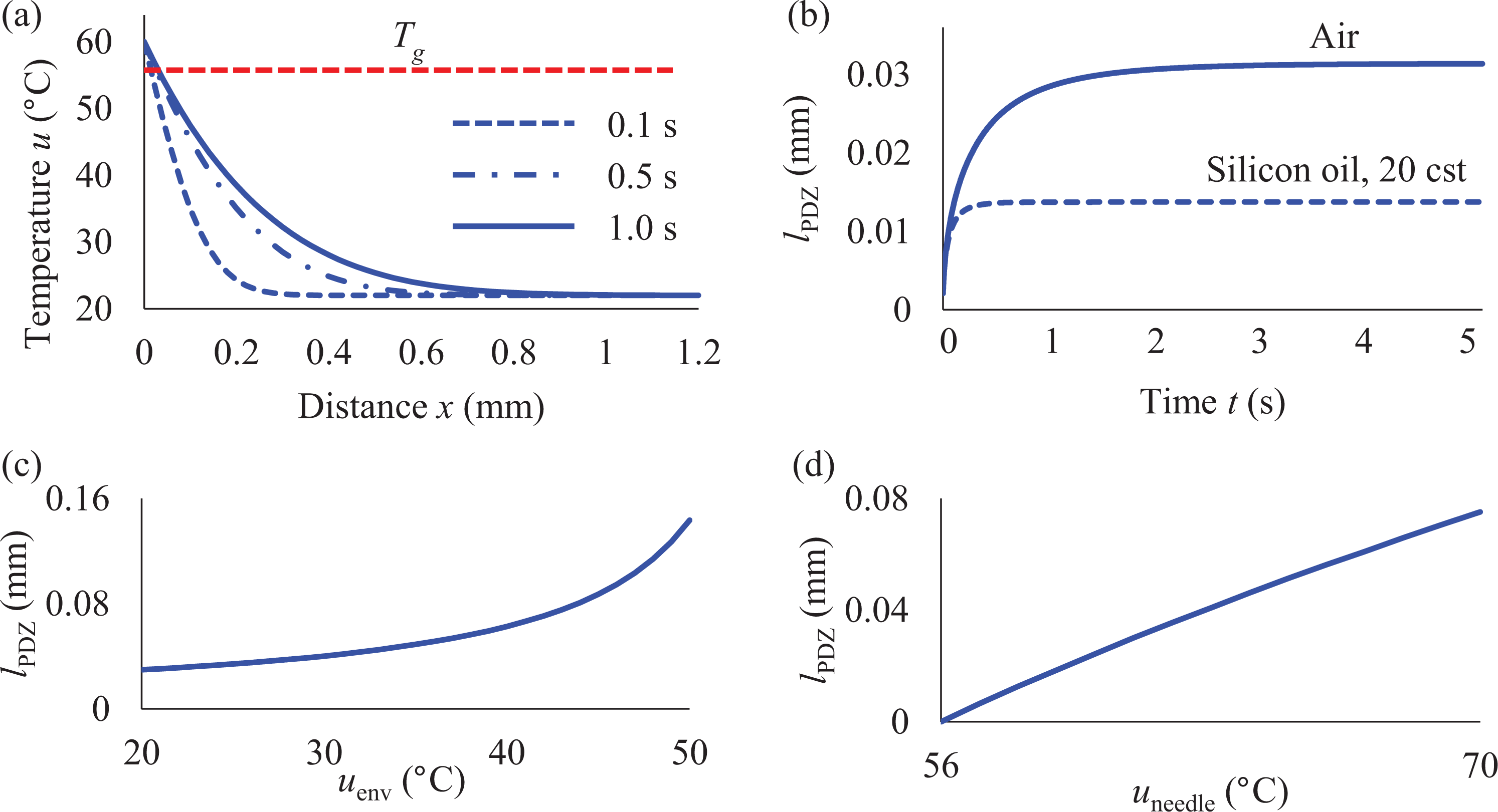
Heat transfer simulation results. (a) The temperature profile along a 120 μm PLA filament at different times in 22°C constant air temperature when the needle temperature is 60°C. (b) The changing of l PDZ in air and silicone oil with time. Both environment temperatures are 22°C and needle temperature 60°C. (c) The final l PDZ in air under different air temperatures. Needle temperature is 60°C. (d) The final l PDZ in air (22°C) under different needle temperatures. PLA: polylactic acid.
It should be noted that heat transfer is a complex process and convective heat transfer between the filament and the environment is subject to many factors. Thus, our heat transfer simulation only approximates the temperature along the filament. It does help to study the order of magnitude of l PDZ and understand the thermal property of the filament during the fabrication process.
Magnet angle planner
With the developed bending theory and accuracy analysis, any shapes composed of sharp bends and continuous bends can be fabricated. However, in order to automate the fabrication process and achieve the desired bending angle for each bend, a parameter related to each bending angle needs to be controlled throughout the fabrication process. We find that during each bending, the already-formed part of the microrobot will rotate itself as a rigid body, thus the heading of the tip magnet will change along with the rotation of the structure. This suggests that the heading of the tip magnet can represent the bending angle α in each bending, and by tracking and controlling it during the feeding of the filament, the fabrication process can be controlled and the final shape of the microrobot will be formed as desired.
Here, we define the magnet angle α to be the angle between the magnet axis and the needle axis. To know the magnet angle α at a certain length of the filament, the following magnet angle planner is developed. For an example shape shown in Figure 5(a), the length of the filament is normalized from S = 0 to S = 1 from the magnet side of the shape to the other end. Suppose that there is a point P traveling from S = 1 to S = 0 along the path, at any given S, the needle axis is aligned with its velocity vector
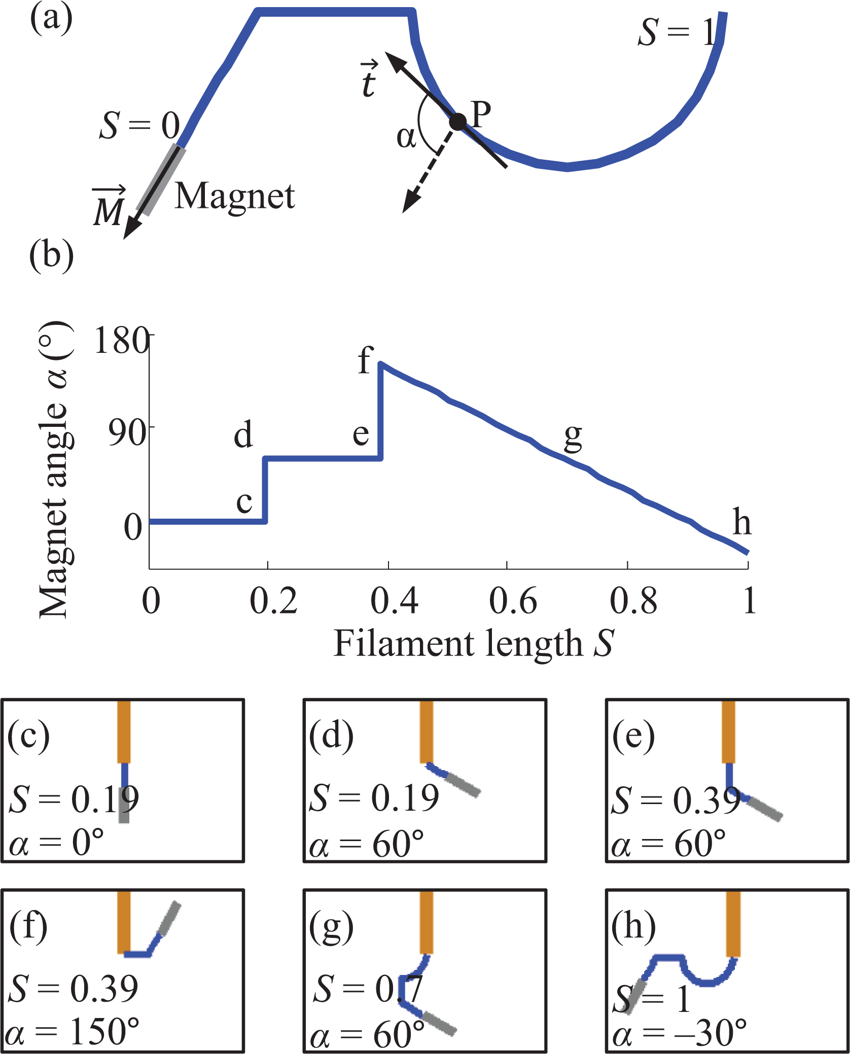
Magnet angle planner. (a) Geometric model of the magnet angle planner. (b) The desired magnet angle from S = 0 to S = 1 for the shape shown in (a). (c) to (h) Snapshots of fabrication simulation for the desired shape shown in (a). The filament length S and magnet angle α are shown in each frame; (c) to (h) correspond to points c to h in (b).
Shape creation potential
Using the magnet angle planner, a desired shape can be formed automatically. However, the target shape is not arbitrary due to the fabrication concept itself, and it is necessary to examine whether a desire shape is valid before fabrication. Two types of inherent limitations will apply during the fabrication process.
The first limitation is induced when the tip magnet hits the injection needle during the fabrication process, as shown in Figure 6(a). When the tip magnet is approaching the needle at angle α, introduced by the size of the magnet, the minimum distance between the needle and the tip of the filament is

where rn is the radius of the needle, rm is the radius of the magnet, and lm is the length of the magnet. Based on this limitation, no totally enclosed shapes can be fabricated, and the minimum distance between the two ends of the filament of a shape will be d, depending on the angle of the magnet.

Shape creation potential. (a) magnet hitting the needle and (b) filament hitting the needle.
The second limitation will apply when the formed structure of the filament hits the needle, as shown in Figure 6(b). In this scenario, disregarding of the angle of the tip magnet, the minimum distance between the needle and the filament is

where rf is the radius of the filament. Because of this limitation, the minimum distance between any two parallel filament segments in a shape will be d.
Results and discussion
Fabrication setup
Material selection and filament fabrication
Among thermoplastic materials, PLA is selected as the filament material due to its low Tg (≅56°C) and its semicrystalline structure, which ensures a uniform thermal property along the filament and makes the fabrication process more predictable. It is also one of the commonly used materials for 3-D printing. Another advantage of PLA over other thermoplastics is that it is derived from renewable resources and biodegradable, and thus not inclined to be harmful in bio-related applications. However, other thermoplastics such as Acrylonitrile Butadiene Styrene (ABS) and nylon can also be used for the fabrication based on different environment temperature requirements and applications. PLA filament of 100–120 μm in diameter is prefabricated using a custom hot extrusion method from 1.75 mm filament intended for use in 3-D printing. In this prefabrication, the filament is extruded at 225°C through an extrusion nozzle of inner diameter 200 μm. Extrusion is done vertically and therefore the filament is pulled by its own weight, creating a uniform diameter along the filament. The extruded filament diameter can be adjusted by changing pulling speed of the extruded filament. Unlike filaments readily available for purchase, negligible residual stress is present in this filament, which is necessary for use in the fabrication of microrobots.
Magnetic field, filament feeding, and heating system
The magnetic fields for fabrication and subsequent motion control of microrobots are generated using a custom magnetic coil system, as shown in Figure 7(a) to (b). The prototype coil system is composed of two pairs of orthogonal Helmholtz coils and can generate nearly uniform magnetic fields of up to 14 mT and at frequencies up to 120 Hz in a vertical plane. The generated magnetic field decreases by at most 7% at the edge of the workspace of 6.75 × 3.50 × 9.43 cm3. The field produced by each coil is proportional to the current through the coil, which is controlled by amplifiers (ADVANCED Motion Controls, 30A8; Camarillo, California, USA) and directed by an analog output card (SENSORAY, Model 826, Tigard, Oregon, USA) from a custom Linux-based C-code software. The feeding of the filament is controlled by a custom filament feeder driven by a stepper motor as shown in Figure 7(c) to (d), and feeding resolution of up to 4.3 μm can be achieved. The needle is heated by resistance wire wrapped around it as shown in Figure 7(d), the temperature is measured by a thermocouple, and feedback control of the needle temperature is performed along for automated fabrication. A camera (NET New Electronic Technology Gmbh, FOculus FO124TB, Finning, Germany) is mounted to the side of the coil system to detect the magnet angle.

Prototype of magnetic in situ microrobot fabrication system. (a) and (b) Side view and front view of the coil system. The filament feeder is placed on the coil system, and the tip of the needle is in the center of the coil system. (c) and (d) Side view and front view of the filament feeder. The filament is fed through the needle by the driving shaft attached to the shaft of the stepper motor. The detail of the tip of the needle with heating wire wrapped around is shown in the inset of (d).
Magnet detection and controller
By processing the image taken from the side camera during the fabrication, the angle of the magnet is detected and then controlled by a proportional–integral (PI) controller.
In order to detect the angle of the tip magnet, we use a cylindrical magnet thicker than the filament as the tip magnet. Examples of the image processing results after each major step are shown in Figure 8(a) to (d). The grayscale image captured by the camera is first converted into a binary image, where the needle, filament, and magnet appear to be black. The needle area is then removed from the image to define the region of interest for the next step. Then, a morphological closing operation (a dilation followed by an erosion) is performed using a circular structure element that is thicker than the filament but thinner than the magnet, such that the filament will disappear after the dilation operation, leaving only the magnet area that appears to be a rectangle with rounded corners. The contour of the area is then detected and fitted into a rectangle. The orientation of the rectangle will represent the angle of the magnet.

Magnet detection and magnet angle controller. (a) and (d) Image processing results after each major step of the magnet detection algorithm. (e) The design of the PI magnet angle controller with maximum allowed magnetic field angle. PI: proportional–integral.
To control the angle α of the magnet using magnetic field, the magnitude of the magnetic field is set as a constant (14 mT in the experiment), while its angle αB is dictated by a PI controller with saturation, as shown in the following equation

where ▵α is the difference between the desired magnet angle and the actual magnet angle, Kp
and Ki
are the coefficients of the proportional and integral terms of the controller, and αB
max is the maximum allowed angle of the magnetic field, which works as a saturation term in the controller. The αB
max is set to be 90° away from the magnet angle as the magnetic torque will decrease when the angle between the field and magnet exceeds 90° according to equation (1), so the applied magnetic field is always between
Filament bending experiments
Before any fabrication experiments using the prefabricated PLA filament can be done, some properties of the filament need to be studied to help determine some parameters used in fabrication experiment. Thus, in the following experiments, we show bending the filament at different environment temperatures to help us determine the needle temperatures for bending and feeding. The filament bending experiment using needles of different inner diameters is also conducted to verify the theory proposed in section “Study of PDZ and bending accuracy.” The resisting torque of the filament at PDZ is also calibrated such that we know the size of tip magnet in order to achieve a certain bending angle.
Bending under different PDZ conditions
As discussed in section “Study of PDZ and bending accuracy,” the l PDZ is affected by the needle temperature and the inner diameter of the needle. Increasing the needle temperature will decrease the stiffness of the filament but also increase the l PDZ, resulting in less accurate discrete bending. The nominal Tg of PLA is 56°C, suggesting that when the temperature is higher than that, the stiffness of PLA will decrease to a minimal value. To further investigate the minimum temperature that can result in relatively large plastic deformation, the filament is bent in increasing ambient environment temperature under a horizontal magnetic field, and the bending angle is recorded as shown in Figure 9. The experimental data reveals that plastic deformation begins to happen at around 40°C; between 40°C and 50°C, plastic and elastic deformation coexist in the filament; at temperature higher than 60°C, plastic deformation reaches its maximum. Therefore, in the fabrication experiment, we feed the filament when the temperature is below 40°C and conduct the bending when the temperature is above 60°C.

Bending angle at different environment temperatures. The PLA filament (120 µm in diameter, 7 mm in length) is vertically fixed and immerged in water, a cylindrical magnet (Φ0.3 mm, length 0.5 mm) and horizontal magnetic fields of 1, 2, and 3 mT are applied in three different trials. The bending angle is normalized to the maximum bending angle of each trial. PLA: polylactic acid.
The inner diameter of the needle is another factor that affects the shape of PDZ. To experimentally study the effect of needle thickness on the PDZ, needles of different inner diameters are used to bend the filament. The diameter of the filament used is 220 μm, and tip magnet of Φ0.75 mm × 1 mm is used. The inner diameters of the needles are 260 μm, 413 μm, and 838 μm. In the three cases, the filament is controlled to bend to 60° off the vertical axis. After the filament is cooled down and taken out of the needle, the actual PDZ is shown in Figure 10. The results suggest that thicker needle will increase the l PDZ and thus affect the sharpness of the bending. The actual bending angle in the three cases is also measured and compared to the desired bending angle. In accordance with the expectation, the error of the bending angle also increases with the inner diameter of the needle, so the inner diameter of the needle should be as close as possible to the thickness of the filament in fabrication.

The bent filament in needles of different inner diameters: (a) 260 μm, (b) 413 μm, and (c) 838 μm.
Resisting torque calibration and single bend experiment
According to the bending mechanics model, by neglecting the resisting torque of the filament, a larger tip magnet will result in larger bending angle under the same condition. To get a more accurate bending angle model and decide the size of tip magnet to use, the resisting torque of the filament needs to be calibrated experimentally due to its difficulty to model. The experiment setup of calibrating the resisting torque is illustrated in Figure 11(a). The magnet is hanged horizontally though a vertical long thin nylon string, such that when the needle is heated up, the horizontal pulling force of the string can be neglected and the resisting torque equals to the applied magnetic torque only. Five trials of resisting torque calibration are conducted, where the lengths of the horizontally extended filament from the needle are 2, 4, 6, 8, and 10 mm, respectively.

(a) Experiment setup for resisting torque calibration. (b) The results of resisting torque calibration for five trials when the extended filament length L is 2, 4, 6, 8, and 10 mm, respectively. (c) The experiment and simulation results of filament bending experiment using 1, 2, and 4 tip magnets. The simulation results are shown in dashed line.
The results of the calibrated resisting torque at different bending angles for the five trials are shown in Figure 11(b). The results show the consistency of the resisting torque at each bending angle regardless of the extended filament length. It is expected that the resisting torque is independent of the extended filament length, as the resisting torque is caused by the viscoelastic creep at the PDZ which is subject to the filament material properties and the bending angle. The resisting torque increases with the bending angle, suggesting that the creep strain will increase with the applied stress. By fitting the averaged resisting torque into a linear relationship with the bending angle, the resisting torque is calibrated as
With the calibrated resisting torque for 120 μm PLA filament at 60°C, filament bending experiments are conducted to verify the accuracy of the calibration. The same filament as in the resisting torque calibration is used and the needle is vertically fixed. The length of the exposed filament is 7 mm. Horizontal magnetic fields are applied as large as 14 mT to bend the filament. Up to four identical magnets (Φ0.3 mm × 0.5 mm) are used in the bending experiment. The agreement between the experimental and simulated bending angle shown in Figure 11(c) suggests that the calibration of resisting torque is accurate enough and the bending mechanics model can be used to predict the bending angle. Using the bending model, it is calculated that one magnet can bend the filament to 90° when the filament is shorter than 4.85 mm, while the filament can be as long as 75.5 mm in order to bend to 90° when two magnets are used as the tip magnet. As most shapes we fabricate are at the scale of 5 mm, one magnet will be enough to get enough bending angle, especially when the filament diameter is smaller than 120 μm.
Microrobot fabrication experiments
Fabrication of different shapes
To demonstrate the effectiveness of the in situ fabrication method with custom produced filaments, as shown in Figure 12(g) and (h), different shapes containing both discrete and continuous bends are made using the prefabricated PLA filament. The tip magnet used is one cylindrical neodymium magnet (Φ0.3 mm × 0.5 mm) and is manually glued to the end of the filament using super glue. All the demonstrated shapes are each fabricated in less than 3 min. As most fabrication time is taken by filament bending, the fabrication time can be even shortened by tuning the parameters of the magnet angle controller to make the bending process faster.

Fabricated microrobots of different shapes. (a) to (f) Snapshots of the fabrication process of the arch-shaped microrobot in chronological order. (g) to (i) Demonstration of the arch-shaped microrobot, a stair-shaped microrobot and a spiral-shaped microrobot. The desired path is shown in dashed line under the actual shape. (j) The filament-magnet setup for removing a microrobot is inserted into the workspace. (k) The microrobot is attached to the removing magnet by magnetic attraction.
The averaged shape deviation D avg is used to characterize the accuracy of the fabricated shape, and this value is measured as the averaged distance between each corresponding points on the actual and desired shape path. To calculate D avg, the actual path is superimposed on the desired path at the same scale, and a minimum area A min of the space enclosed by the two paths is found and calculated by changing the relative orientation and position of the two paths. The area A min is then normalized to the length of the desired shape to get D avg. The D avg for the arch, stair, and spiral shaped microrobots is 59.5 μm, 40.76 μm, and 117.85 μm, respectively. Shapes with more continuous bends appear to have larger D avg, but it is still at the same order of magnitude as the thickness of the filament, and all the D avg are within 1% of the total length of the corresponding path, which shows a high accuracy of the fabricated shapes.
We also show that a fabricated microrobot can be removed out of its workspace. To achieve the removal, as shown in Figure 12(j) to (k), there is an arch-shaped microrobot inside the workspace, and another filament with a tip magnet attached at its end is inserted into the microrobot workspace through the needle. The free ends of tip magnet for removal and that on the microrobot have opposite polarities such that they can be attracted by each other as they approach. As the microrobot is attracted by the removing tip magnet, we slowly retract the filament with the needle being heated, thus the microrobot straightens itself as the retraction and finally gets removed out of the workspace. The removing process of the microrobot is a reverse of its fabrication process.
Functional device demonstration: A micro-gripper
Here, we introduce a micro-gripper fabricated using the in situ fabrication method as a functional device for advanced application. As shown in Figure 13(a), a segment of 100-μm thick PLA filament with one tip magnet (Φ0.75 mm × 1 mm) attached at each end is fed through a hypodermic needle and bent into a gripper shape. The feeding of the filament segment is achieved by pushing it using another filament through the filament feeder. After the formation of the gripper, the gripper is directly pushed outside of the needle by the feeding filament. Thus, the gripper can be fabricated in situ and deployed into its workspace without direct human interference. As the wall of the needle is magnetic material, without any pushing, the filament segment can hang on to the needle by magnetic attraction between the wall of the needle and the magnet inside the needle. The needle is inserted into an enclosed acrylic container (L45 × W25 × H15 mm3) filled with silicone oil (viscosity 20 cSt; Sigma-Aldrich, St Louis, Missouri, USA) through an access hole.

Demonstration of the micro-gripper. (a) The concept of the micro-gripper. (b) The gap distance versus field strength of the micro-gripper. The assembly of the cage is shown in (c) to (i) and disassembly is shown in (i) to (j) using the micro-gripper. Pieces A and C are the two halves of the cage, and piece B is the cell analog.
As the tip magnets are magnetized to point outward and the overall magnetization of the gripper is at the direction of its central axis, the two symmetrical arms will deflect toward the center when a magnetic field along the central axis is applied, causing the closing motion of the micro-gripper. 29 Taking advantage of the net magnetization of the micro-gripper, the gripper can be controlled to move using stick-slip motion, 30 while the opening and closing motion of its arms can be controlled by changing the magnitude of the applied magnetic field. The relationship between the gap distance and the field strength for a fabricated gripper is shown in Figure 13(b).
As shown in Figure 13(c) to (j), the micro-gripper is controlled to assemble a cage for a 1.6 mm disk (piece B in Figure 13(c)) to mimic the situation of assembling a cell into a cage for cell culturing. The cage and the disk are laser cut liquid plastic (Smooth-Cast 310, Smooth-On, Macungie, Pennsylvania, USA). The opening of the first half (piece A) of the cage is narrower than the normal width of the gripper. To manipulate this piece, the gripper deflected to close its gap before entering piece A. This will create a secure contact between the gripper and the wall of piece A. After finishing the assembly, taking advantage of the handle on piece C, disassembly of the cage is also performed.
Functional device demonstration: A micro-spring
As another functional device demonstration, a mobile micro-spring is fabricated. This micro-spring can be used as a manipulation tool with force feedback capability. 7 By measuring the deflection of the calibrated micro-spring through optical detection, the manipulation force of the micro-spring can be calculated.
The micro-spring is fabricated using a PLA filament of diameter 120 μm and one tip magnet (Φ0.75 mm × 1 mm) is used. After the formation of the micro-spring, in order to release the spring from the filament without accessing into the workspace, the needle is pulled out together with the formed structure until the tip of the micro-spring just reaches the access whole; the tip of the micro-spring is then cut using a blade.
The essential function of the micro-spring is to do force sensing–related manipulation in confined spaces, thus here we use the micro-spring to test the stiffness of a flexible beam inside an enclosed workspace to demonstrate its functionality. Inside the workspace, there is a cantilever beam made with silicone rubber (Smooth-On, Mold Max 20). Actuated by a permanent magnet, the micro-spring is controlled to push against the beam, as shown in Figure 14(c) to (d). As the stiffness of the micro-spring is calibrated as 2.17 N/m, using the formula of cantilever beam deflection at small angle,

Demonstration of the micro-spring. (a) The fabricated micro-spring before cutting off from the needle. (b) Snapshot at the moment when the micro-spring is just cut off from the needle. (c) The micro-spring original length (7.46 mm) is approaching the beam (16.96 mm long, 1.62 mm thick, and 2.23 mm high). (d) The micro-spring pushed the beam to cause a deflection of the beam. The length of the deflection of the micro-spring is 0.86 mm, the deflection of the beam at the pushed point is 1.21 mm, and the distance between the pushed point and the joint is 13.69 mm. (e) The deflection–force plot for the stiffness calibration of the micro-spring. The blue dots are data taken from the calibration and red line is the fitted line for its stiffness. The inset shows the calibration setup, where a force sensor is aligned with the micro-spring.
Conclusion
The new fabrication method presented in this article has the potential to simplify the fabrication process of existing microrobots and also creates the possibility of fabricating more complex microrobot shapes for advanced functionalities. In addition, the process of transporting the microrobot from a fabrication system into its workspace is no longer a problem as the microrobot is directly fabricated in situ through an injection needle. This allows the reduction in the size of the access hole to the diameter of the injection needle and facilitates further operation of the microrobot.
In this study, the tip magnet we used is thicker than the filament to induce enough bending moment, thus the needle inner diameter has to be larger than both the magnet and the filament. However, with large enough magnetic fields, the tip magnet or even magnetic particles could be embedded into the tip of the filament, and this will further decrease the size of the needle and the fabricated device. As a potential application, we show in this article the formation of a micro-gripper and micro-spring using the in situ fabrication method. With control of both force and torque applied on the tip magnet, any mobile microrobot that can be approximated by a wireframe structure can be fabricated using the fabrication method. These devices include but are not limited to helical swimmers, porous microrobots for cell culture, and medical devices such as stents for artery treatment.
Footnotes
Declaration of conflicting interests
The author(s) declared no potential conflicts of interest with respect to the research, authorship, and/or publication of this article.
Funding
The author(s) disclosed receipt of the following financial support for the research, authorship, and/or publication of this article: This work was supported by the Natural Sciences and Engineering Research Council of Canada Discovery Grants Program (grant #2014-04703).