
Abstract
Vision-based object tracking has lots of applications in robotics, like surveillance, navigation, motion capturing, and so on. However, the existing object tracking systems still suffer from the challenging problem of high computation consumption in the image processing algorithms. The problem can prevent current systems from being used in many robotic applications which have limitations of payload and power, for example, micro air vehicles. In these applications, the central processing unit- or graphics processing unit-based computers are not good choices due to the high weight and power consumption. To address the problem, this article proposed a real-time object tracking system based on field-programmable gate array, convolution neural network, and visual servo technology. The time-consuming image processing algorithms, such as distortion correction, color space convertor, and Sobel edge, Harris corner features detector, and convolution neural network were redesigned using the programmable gates in field-programmable gate array. Based on the field-programmable gate array-based image processing, an image-based visual servo controller was designed to drive a two degree of freedom manipulator to track the target in real time. Finally, experiments on the proposed system were performed to illustrate the effectiveness of the real-time object tracking system.
Introduction
Object tracking is one of the fundamental and interesting topics in robotic and computer vision system. Applications include surveillance, navigation, motion capturing, and so on. Generally, the visual object tracking contains steps of processing images to extract color, edge, and other feature information, which are time-consuming. For example, the Soble edge detector and Harris corner detector have been proved with good robustness to light illumination changing and random noises, and they still rely on software processing in personal computers due to the high computation consumption. However, the personal computers have the problems of high weight and power consumption and can prevent the object tracking from being applied in the real-time applications with limited computation resources. Therefore, it is in high demand to find a solution for the real-time image processing on lightweight hardware of low power consumption.
Recently, more and more image processing algorithms were implemented on graphics processing unit (GPU)- or field-programmable gate array (FPGA)-based image processing platform due to their good parallelized image processing ability. Acharya et al. implemented the scale-invariant feature transform (SIFT) feature detector on GPU device to achieve more than 55 frames per second (fps) for a video graphics array (VGA) resolution image. 1 Heymann et al. introduced an impressive efficiency of SIFT feature detector based on GPU device. 2 Lu et al. 3 used parallel Hough transforms to detect straight line feature by using FPGA. Hernandez-Lopez et al. 4 proposed an FPGA-based image interesting point detection algorithm, which implemented SUSAN and Harris corner detection on the flexible FPGA device. The feature extraction rate can achieve 161 fps at 30 megapixel resolution. Isakova et al. 5 implemented a stereo vision algorithm using FPGA and solved the stereo calibration and stereo matching problem only by the FPGA device. It proved the high image data computation ability of FPGA device. Shimizu and Hirai 6 utilized complementary metal–oxide–semiconductor (CMOS) and FPGA to build a real-time and robust target tracking system, using four double data rate (DDR) RAM to store the high frame rate (up to 1000 fps) images. Possa et al. 7 proposed low memory required edge and corner detectors on FPGA. They concluded the advantages of the FPGA-based image processing system by comparing the efficiency and the power consumption between GPU- and FPGA-based architectures.
Chang et al. 8 proposed a high-speed Harris corner detector on FPGA device, with high efficiency and high frame rate (540 fps). Kryjak et al. 9 realized a high-resolution image-processing platform based on FPGA; their background generation and target detection algorithm were of high efficiency and robustness. Anderson et al. 10 proposed an FPGA-based vision system for an autonomous mobile robot, including processes of object detection, tracking, and path planning. Dillinger et al. 11 used an FPGA- and digital signal processor (DSP)-based image processing system to detect falling objects. The Zernike moments method is useful for the object recognition in binary image, but the processing speed of moments by PC cannot fulfill the real-time application requirement. Liu et al. 12 proposed an FPGA-based Zernike moments calculation method to detect the target in laser image in real time. Santos and Ferreira 13 proposed an FPGA- and fuzzy logic-based position tracking system and proved the possibility of embedding a high-level logic controller into an FPGA device. Okumura et al. 14 proposed a real-time image mosaicing system of high frame rate (up to 500 fps) on FPGA device. Tippetts et al. 15 proposed an FPGA-based vision system and applied it on a small unmanned vehicle and illustrated the performance of real-time target tracking. The existing approaches have proved the FPGA’s ability of running the complicate algorithms of image processing and high-level logic calculation. Compared to the PC-based image processing with long time delay, the pipeline-based image processing on FPGA shows a better performance on time consumption. The advantages of small size and low weight of FPGA-based image processing system are more useful for the embedded vision applications. However, the widely used image processing algorithms were designed for CPU device, to implement these algorithms on FPGA device is a challenging and time-consuming work. Different from the FPGA/DSP or FPGA/Advanced RISC Machine (ARM) hybrid systems 11,16 in the proposed system, FPGA and ARM core are putting together inside the ZYNQ device. Between the two processing cores, an Advanced Extensible Interface (AXI) bus can transfer data with a high band width and high frequency. Based on this AXI bus, we can implement both the image processing algorithm and robot control algorithm in a single chip.
The main contributions of this article are twofold. First, a new FPGA-based vision system was proposed for object tracking objective, where several critical and real-time image processing modules, like image undistortion, color space convertor, edge and corner detectors, and the convolution neural network (CNN) were implemented using the programmable gates in FPGA. Second, a visual servoing-based controller was designed to drive a two degree of freedom (DOF) manipulator to track fast-moving target, and the whole visual servoing scheme was implemented on a ZYNQ system. It is noting that all the image processing and visual servoing were implemented on the same chip and thus can exhibit the abilities of low power consumption and lightweight.
The rest of this article is organized as follows: In section “Image processing on FPGA,” the image processing modules including the CNN module implemented on FPGA device are introduced, followed by the image-based visual servo controller in section “Visual servoing-based object tracking.” In section “Experiments,” experiments are demonstrated to illustrate the system performance. Finally, conclusions and discussions are given in section “Conclusion.”
Image processing on FPGA
The proposed real-time object tracking system is mainly composed of a Xilinx ZYNQ-7000 system-on-a-chip (SOC) core board, a 2-DOF manipulator, and a digital CMOS sensor with 120 degrees field of view. Figure 1 shows the software framework of the proposed on-chip object tracking system. As shown in Figure 1, sequenced images are transferred from the CMOS module to the frame buffer in the FPGA core and then processed parallelly with the image processing modules in FPGA. The extracted information from the processing is utilized as the input for the CNN. The classification result of CNN was used for the visual servo controller to realize real-time object tracking; in the same FPGA SOC, the visual servo control algorithm is implemented in the ARM core. Using the AXI bus, the feedback information can be transferred to the ARM core without any external electric connection. In this section, the design details of the image processing modules will be introduced, including image undistortion, color space convertor, Sobel edge detector, and Harris corner detector.

Structure of the ZYNQ-based tracking system.
Image undistortion
Due to the lens or CMOS sensor imperfection, images captured are always distorted and generally need a correction procedure before being forwarded to further processing. The distortion can be classified into three types, that is, the radial distortion, tangential distortion, and optical center shift. Generally, considering radial distortion only can satisfy most practical applications, and therefore the well-known distortion model given by Zhang 17 is applied, that is

where

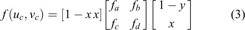
where (fx, fy) denotes the focal length of the camera, and α represents the angle between the x and y CMOS axes. (cx, cy) denotes the image’s center shift. These parameters can be calibrated offline through the MATLAB calibration toolbox 18 and are then stored as constants in the FPGA SOC. The distorted and undistorted images do not correspond to each other pixel to pixel due to the nonlinear distortion transformation. In the article, the bilinear interpolation method is used to calculate the pixel value of the undistorted image from the neighboring pixels, as follows
where

(a) Undistortion module structure and (b) logic schematic of undistortion module.
Figure 3 illustrates an undistortion example. The original frame and the undistorted frames by our system and MATLAB are shown in Figure 3(a) to (c), respectively. The edge of the chessboard undistorted by MATLAB was smoother than that of our system. The reason is that the float multiplier of our designed system has two decimal places of accuracy for better real-time performance and lower computation cost. Fortunately, the lower accuracy will not affect the final performance according to our experimental results.

Calibration result: (a) original image, (b) corrected image by FPGA, and (c) corrected image by MATLAB toolbox. FPGA: field-programmable gate array.
Color space conversion
After undistortion, the undistorted image was ready for further processing algorithms, that is, the color convertor, the edge detector, and corner detector. It is worth noting that the algorithms can be optionally selected to process by a switching architecture designed in FPGA. Hue, saturation, and value (HSV) color space 19 has been proved to be more robust than red, green, blue (RGB) in color tracking applications. Here, the RGB-to-HSV convertor in the FPGA will be introduced in detail. HSV is actually a nonlinear transform of RGB color space. The conversion from RGB to HSV is given as

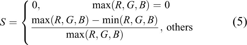

According to equations (4) to (6), the logic of HSV color space convertor is designed as shown in Figure 4. The module uses the RGB channels of each pixel as input and outputs the desired HSV channels. The difference between R, G, B values was calculated by the substractors in FPGA device, and the comparison progress between three color values was implemented by the comparators. With these two progresses in FPGA, the R, G, B values can be finally converted to H, S, V color space. Because the pixels of the whole image can be processed parallelly by the separated color convertor modules, the computation speed is much faster than those in PC-based systems.
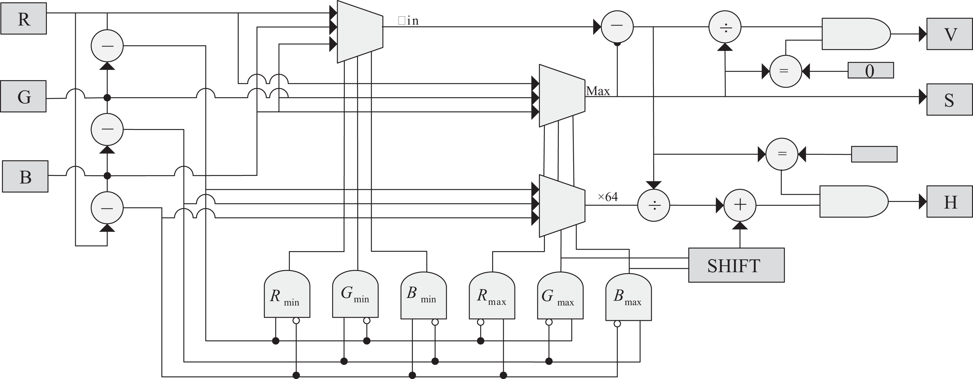
The logic of color convertor.
Features extraction for edge and corner
For many vision applications like object tracking, visual navigation, and stereo vision, it is in high demand to extract edge and corner features from images. In this article, we will propose FPGA logic designs for the widely used Sobel edge and Harris corner. Because they are simple but very efficient for object tracking, the Sobel edge and Harris corner features extracted from the designed FPGA logic module will be used as the feedback information for visual servo control.
Edge detector
The edge feature can represent the contour of a target. Here, the Sobel operator
14
algorithm was selected to collect the edge information. The Sobel edge detection is divided into two steps: Calculate the vertical or horizontal Sobel operators Gx and Gy by convoluting with the gradient kernels on x and y directions respectively, given as

where ωx and ωy denote the gradient kernels on x and y directions, respectively, that is

Calculate the arithmetic square root Gs of the values Gx and Gy as follows

where Gx and Gy denote the gradients on x and y direction, respectively. With the predefined threshold T, the binary image of Sobel edge detector can be obtained. Figure 5 illustrates the FPGA logic of the Sobel edge detection. In FPGA, the calculation in equation (9) is consisted of comparator, subtractor, and bits shifter. With the result of the gradient calculation, the predefined threshold value T has been used to remove the edges with small gradients. Figure 6 illustrates a detection example of the designed Sobel module. It is seen that most edges in the result image are sharp and continuous.

Schematic of the Sobel edge and Harris corner detector.

(a) Original image and (b) Sobel edge image.
Harris corner detector
Based on the operation of Sobel detector, the Harris corner detection 20 is further implemented. To detect Harris corners, the Harris matrix is first calculated as follows

where ω represents a 3 × 3 Gaussian convolution kernel and Gx and Gy are the vertical or horizontal Sobel operators calculated in the previous section. Then, the Harris corner evaluation value V is calculated as

where k is a parameter in the range of 0.04–0.06, det(H) denotes the determinant of matrix H, and trace(H) denotes the trace of matrix H. The determinant and trace are calculated as

If the corner value V is larger than a predefined threshold THarris, it means a Harris corner exists at the pixel location. To further remove the noisy corners, the non-max algorithm is used, which compares the pixel gray value to the eight surrounding pixels. If the gray value is smaller or bigger than all the eight surrounding pixels, the corner is removed. Figure 5 illustrates the FPGA logic of the designed Harris corner detector, containing six submodules as follows: Calculate the vertical and horizontal Sobel operator Gx and Gy. This convolution process is implemented on FPGA device by multiplying the pixel value with the corresponding value in the gradient kernels on the x and y directions. Calculate the values of Store the gradient value Calculate the determinant det(H) and the trace trace(H) of the Harris corner matrix by using the summator and multiplier and then calculate the Harris corner evaluation value V. Compare the Harris corner response value V with the threshold value T. If the value is smaller than threshold value, set the pixel value to zero. Finally, compare the Harris corner response value V with the eight surrounding pixel values. If the value of this pixel is smaller than all the surrounding pixels, treat it as a noise pixel and set the value to zero.
Figure 7 demonstrates an example of the Harris corner detection with the proposed FPGA-based module. By setting different thresholds, the number of the Harris corners can be controllable. Figure 7(a) and (c) is the original image of two indoor environments. Figure 7(b) and (d) is the detection result of Harris detector. From the result, it is seen that most of the strong corners were detected. The accuracy and quantity are good enough for the most applications.

(a) and (c) The original images captured in two indoor environments; (b) and (d) the results of Harris corner extraction.
Hardware-based CNN implementation
The CNN was recommended to be the state-of-art image classification and recognition algorithm, 21 and the possibility of hardware-based implementation of the algorithm has been proved in the work done by Coric et al. 22 In this section, we will introduce the implementation of the CNN algorithm to realize object detection. The structure of the CNN network can be found in Figure 8. The implementation completes the forward and backward parts: the backward part is implemented on ARM core; the forward part is constructed with convolution and pooling layers. The implementation of the forward part of CNN on FPGA device contains three steps:
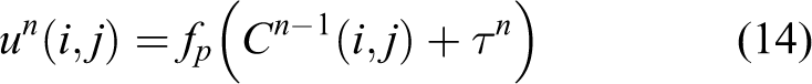
Step 1. Construct the discrete convolution layer

where

The CNN structure. The C represents the convolution layers, and S denotes the pooling layers. CNN: convolution neural network.

FPGA-based CNN module. (a) The line buffer-based 3 × 3 pixel window generator and (b) the schematic of window-based convolution operator. FPGA: field-programmable gate array; CNN: convolution neural network.
Step 2. Construct the pooling layer
Step 3. In many industrial practice, the CNN training was always finished off-line. In this article, the training progress was pretrained on PC, and the trained parameters were stored on ARM device. When power up the device, the trained parameters were loaded to the FPGA-based CNN module to tune the convolution parameters via the AXI bus provided by the ZYNQ device.
Visual servoing-based object tracking
As shown in Figure 10, a CMOS camera is mounted on a 2-DOF pan-tilt cradle head in our object tracking system to realize the automatic tracking of a fast-moving target. Visual servo control technology has attracted increasing attention in robotics due to its high efficiency and accuracy.
23–26
In this section, a visual servo controller is presented to drive the 2-DOF manipulator to track the preselected target object. The image-based visual servo control method is applied in the article, due to its advantages.
27
The color blob or Harris corners extracted by the FPGA-based image processing modules are used to detect the target’s location. As shown in Figure 10(a), denoting

where

where V and ω denote the camera’s translational and angular velocities, respectively, with respect to the base frame,
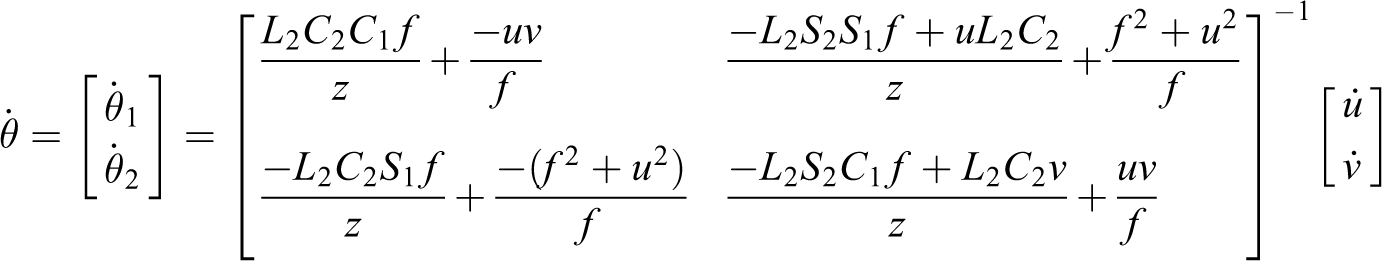

where the relationship between the velocity

where Jt represents the previous estimated Jacobean matrix, and

where U(k) is the control input of the pan-tilt system at the kth sampling time instant, KD is a constant matrix of velocity gain, and KP is an image gain matrix,

(a) Kinematics model of the pan-tilt head and (b) our pan-tilt head tracking system.
Experiments
Two experiments were performed to demonstrate the effectiveness of the proposed object tracking system. The first one illustrated the real-time CNN-based visual servo tracking performance of a ping-pang ball using HSV color blob. The second one illustrated the tracking performance of a small chessboard using the Harris corners. Note that the whole object tracking system integrated all the algorithms in the same Xilinx ZYNQ-7000 SOC core board, and no extra computers are needed to implement the object tracking. For convenience, we utilize a VGA display screen, directly connected to the SOC board, to show the processed image sequences.
Color-based object tracking experiment
Figure 11 shows the snapshots of the color-based tracking of a ping-pang ball. Images are captured from the CMOS camera sequentially and then transferred into the FPGA through an 8-bit digital parallel port realized in the FPGA device. The CNN parameters were pretrained and precached in the SOC. The visual servo controller parameters were selected based on prior experiments.
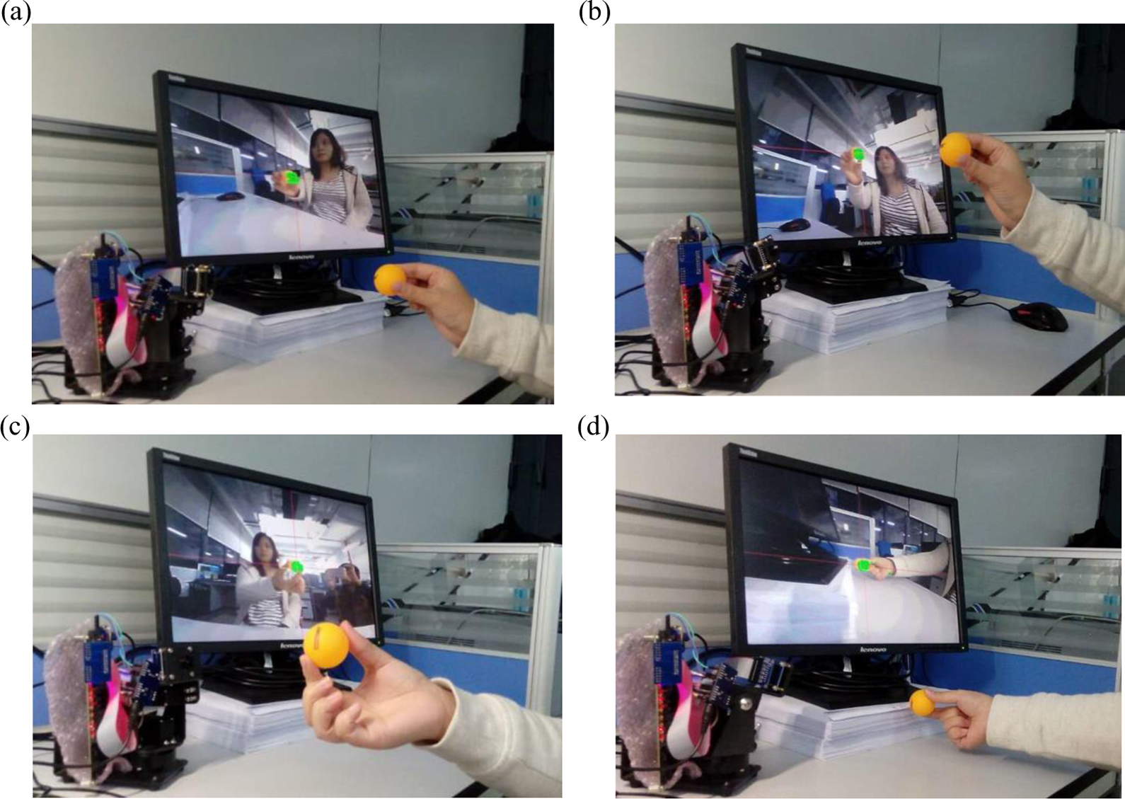
HSV color space-based object tracking. (a) Position A; (b) position B; (c) position C; and (d) position D.
As shown in Figure 11, the target (ping-pang ball) was detected using the color space conversion module, and its position is labeled on the image with green blob. The RGB image was converted to the HSV space, and the Hue information was selected to help separate the target from the background. It can be seen that the tracked target was robustly kept at the center of screen even the target scale changed. Our proposed tracking system can keep tracking the target at 500 fps (resolution: 640 × 480) which is the maximum frame rate of the CMOS image sensor; it means that the tracking rate can even higher when using a CMOS camera with higher frame rate.
Static object tracking experiment based on corner feature
In this experiment, the target to be tracked was fixed while our tracking system was moving. The experiment represents a series of practical applications, for example, target detection from a fast-moving air or ground vehicle. Here, the corner features were utilized to verify the effectiveness of the FPGA-based corner extraction module. Figure 12 illustrates a frame sequence of the static target tracking experiment. A chessboard target was stuck on the wall. The 2-DOF pan-tilt head was requested to keep the target at the image center. When the Harris corners were detected, the object location was recognized by matching the corner cluster and then sent to the ARM core in ZYNQ. The visual servo controller was finally used to drive the robot to make the target be at the image center.

Harris corner-based static object tracking.
Figure 12(d) and (h) shows the trajectory of the target, moving from left upper corner to the center. The experimental result proved the robustness and accuracy of our vision system. It is seen that the target’s location (indicated by black lines) automatically and quickly (within 2 s) converged to the image center (indicated by red lines). The stable error of the tracking algorithm (smaller than 2 pixels) depends on not only the tracking algorithm but also the control accuracy of servo motors.
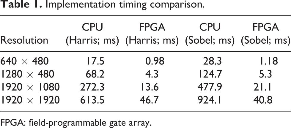
Table 1 shows the comparison of the computation performance for Harris and Sobel algorithm implementation on PC (CPU: i7 4500u, memory: 8GDDR3) and FPGA. From the table, it can be seen that the FPGA-based approach exhibits much better performance than CPU. The FPGA resource consumption is shown in Table 2, including the resource consumption of the color convertor, Sobel edge detector, and Harris corner extractor. It can be seen that 65% block RAM was used for the data buffering, about 56% of logic cells were occupied, and 27% DSP module was used for the floating multiply. There are still about half of logic resources that are free of usage, and it means the proposed approach can be further improved.
Implementation timing comparison.
FPGA: field-programmable gate array.
Implementation resource consumption of FPGA.

FPGA: field-programmable gate array; DSP: digital signal processor; LUT: lookup table.
Conclusion
This article presents a real-time object tracking system based on FPGA and CNN. The image processing algorithms, including image undistortion, color space convertor, and Sobel edge, Harris corner features detectors, and CNN were redesigned and implemented with the programmable gates in the FPGA core of the ZYNQ SOC. Further, the visual servo controller was designed and implemented in the ARM core of the ZYNQ SOC, driving a 2-DOF pan-tile cradle head to realize the object tracking. The image processing, CNN, and visual servo control are implemented in the same ZYNQ SOC without any external electric connection. Finally, experiments were performed to illustrate the effectiveness of the proposed tracking system. The proposed real-time visual tracking system can be easily applied to robotic applications, like victim detecting and tracking in rescue task, and other real-time tracking applications. Our future work includes the robustness improvement of the object recognition and the extension of its application on the mobile robot navigation and object tracking.
Footnotes
Declaration of conflicting interests
The author(s) declared no potential conflicts of interest with respect to the research, authorship, and/or publication of this article.
Funding
The author(s) disclosed receipt of the following financial support for the research, authorship, and/or publication of this article: The article was supported in part by Hong Kong RGC via grant 14204814, Shenzhen Peacock Plan Team grant (KQTD20140630150243062), Shenzhen Fundamental Research grant (JCYJ20140417172417120) and (JCYJ20140417172417145), Shenzhen Key Laboratory grant (ZDSYS20140508161825065), Shenzhen Science and Innovation Committee grant (JCYJ20140417172417145), and Guangdong Science and Technology Foundation grant (2014A010103007).