
Abstract
Traditional methods and theories on synthesizing parallel mechanisms are not applicable to related researches on hybrid mechanisms, thus hampering the design of innovative coupled mechanisms. Polyhedrons with attractive appearance and particular geometrical construction provide many choices for coupled inventions. A novel mechanism with one translational degree of freedom based on a regular triangular bipyramid is proposed in this article. First, the basic equivalent geometrical model is spliced with new-designed components substituting for vertexes and edges by revolution joints (R-pairs) only. The expected motion for the basic coupled model can be achieved by adding links to modify the constraint sets and arrange spatial allocation of an elementary loop based on the screw theory. Then, the mobility of one branch is calculated to investigate the movability of the novel structure, and a Denavit–Hartenberg (D-H) model with properties of symmetry is implemented to investigate the inverse kinematic analysis. Furthermore, a numerical example is given to verify the correctness of analysis results and related motion simulation is conducted to illustrate the potential application of the proposed novel system as an executing manipulator for mobile robots.
Keywords
Introduction
The need of synthesizing new mechanisms for innovation, especially with symmetric structures, makes researchers to investigate particular structures. In recent years, the coupled mechanisms with the advantages of the serial and parallel mechanisms have been a hot topic. The new type of coupled mechanisms that is characterized by coupled chains, which are always connected for complex multiloop or netting structures between the base and the moving plane, is different from that of the serial and parallel constructions. However, the complicated coupling chains bring about the impossibility to apply generalized methods and theories on parallel structures 1 –7 to the construction of novel coupling mechanisms.
Polyhedral structures, interesting for their geometrical characteristics, are naturally occurring. Appeared first in several areas of mathematics, the use of polyhedron as a novel insight has been extended to chemistry, architecture, mechanism, and other scientific fields. 8 The octahedral invention associated with the so-called Jitterbug motion provided by Fuller in 1948 can be regarded as the first inspired product by polyhedrons. In recent decades, polyhedrons have inspired many innovative coupled mechanisms. Hoberman invented the Hoberman switch-pitch ball, radial expansion/retraction truss structure, and the folding covering panels by connecting different types of polygonal linkages for radial or reversible motion. 9 –11 Many types of rolling robots by combining a set of prismatic pairs, revolution pairs, and parallelogram scaling units based on spatial tetrahedral framework have been presented in literature. 12,13 Laliberté and Gosselin 14 proposed a mechanical arrangement based on a single type of component for the construction of polyhedrons. Wei et al. 15,16 applied a spatial eight-bar linkage to synthesize a series of deployable mechanisms based on different polyhedrons. Ding et al. 17 proposed a novel prism deployable mechanism by polyhedral linkages, which had potential application in aerospace field. Some other polyhedral structures, 18,19 such as the antenna of Mir Space Station designed to be network construction for flexibility and transformation, have already been used in recent years. Cai et al. 20 studied a planar radial expanding linkage with generalized angulated elements. For extensive range and superior performance of polyhedral coupled mechanisms, the researchers also had conducted many theoretical studies on type synthesis approaches and mobility analysis of the focused systems. In 2004, Dai et al. 21 investigated a scalable mechanism and analyzed its mobility by decomposing the mechanism into some elementary parallel mechanisms with single degree of freedom (DOF) based on the screw theory. You 22 came up with the efficiency of the productive application in satellite solar panels and shelters considering the motion characteristics of the Hoberman sphere in 2007. In 2012, Kipper and Söylemez 23 introduced a family of highly overconstrained spatial linkages using the Jitterbug motion introduced by Fuller. Based on the screw theory, Liu et al. 24 proposed a new mobility method for coupled mechanisms by analyzing the motion of the node parts relative to a fixed base and converting the mechanism into a simple equivalent parallel structure. Then, Liu et al. 25,26 improved the method for multiloop coupling mechanisms by altering a loop linkage into generalized limbs and operated conveniently.
As mentioned earlier, polyhedrons characterized by particular geometry and charming symmetry provide scholars the possibility of establishing fundamental framework for inventing polyhedral coupled mechanisms. The studies on type synthesis of innovative coupled mechanisms with polyhedral structures have drawn researchers’ attention. The invented polyhedral structures with coupling connections usually perform excellently. Possessing special output motion, polyhedral coupled mechanisms can transform into suitable configurations conveniently to satisfy different operational requirements. However, the existing coupled mechanisms are not plentiful and related studies have not been developed overall. As thus, it is significant to inventing various new polyhedral coupled mechanisms for increasing the variety of mechanisms and expanding application widely. To enrich the family of the new mechanisms, we present a novel polyhedral coupled mechanism based on the regular triangular bipyramid in this article. The commonness between the polyhedra and coupled structures is used to establish fundamental framework for type synthesis. Our work is scheduled as follows.
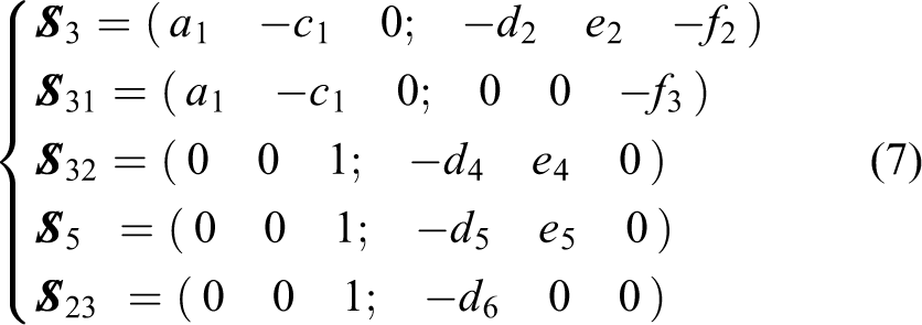
In this article, a novel coupled mechanism based on regular triangular bipyramid is presented. The number of merging edges at every vertex in a regular triangular bipyramid is not identical. By designing three substitutive components for essential elements and adding reasonable links, based on the screw theory, the basic coupled model is obtained in section “Modeling of the novel coupled mechanism.” Then, the mobility and inverse kinematic analysis are conducted to identify motion and symmetry properties. A numerical example is given to verify the analytical results and corresponding simulations are implemented and demonstrate the validity and feasibility of the proposed mechanism in section “Numerical validation and simulation analysis.” Conclusions are drawn in the last section.
Modeling of the novel coupled mechanism
The goal of this section is to establish the basic coupled model based on a regular triangular bipyramid. The polyhedral solid bounded with six identical triangles is selected for the construction of fundamental framework. First, by spatial arrangement and geometrical features of the polyhedral sketch, based on which three types of substitute components are designed and assembled for the original basic model, the relationship of essential elements is elaborated. Then, to obtain a moveable basic coupled model, the unit loop corresponding to a face in a regular triangular bipyramid is extracted and its mobility is modified by adding links based on the screw theory. At last, the whole spatial coupled model is built.
Construction of fundamental framework
According to the connecting condition of each vertex, polyhedrons can be classified to the three types 8 : the regular polyhedra, the semiregular polyhedra, and some special irregular polyhedra. The selected regular triangular bipyramid for type synthesis shown in Figure 1 is a kind of semiregular polyhedra. To clarify the synthesizing method, the geometrical property of a regular triangular bipyramid is first introduced.

Sketch of a regular triangular bipyramid.
Edges and vertexes contained in a polyhedron are essential elements and play an important role in modeling. It is known that the numbers of essential elements in a polyhedral solid satisfy the following Euler formula

where V is the number of vertexes, F is the number of faces, and E is the number of edges.
As shown in Figure 1, a regular triangular bipyramid is composed of six regular triangles. Not all merging conditions at every vertex are the same. Assume V 3 is the number of the vertexes connecting three regular triangles and V 4 is that of four regular triangles. Hence, the relationship between all essential elements of a regular triangular bipyramid is obtained as

Based on the spatial arrangement and relationship between all essential elements of the regular triangular bipyramid, the fundamental framework can be constructed by determining the types of all components and connections of branches in the following steps: (1) Marking all vertexes of a regular triangular bipyramid
Equation (2) explains the relationships between all essential elements in a regular triangular bipyramid and meets equation (1). The two vertexes (V
3 = 2) merging three edges are labeled as A and E; the other three vertexes (V
4 = 3) connecting four edges are labeled as B, C, and D. (2) Selecting components as the base and moving platform for the basic model
Considering the symmetry of the fundamental framework, choose A and E, located symmetrically with identical connections, as the moving platform and the base, respectively. (3) Determining coupled node parts and connecting chains
All branches can be confirmed when the base and the end effector are selected. Except two edges linked to A and E directly, every two of B, C, and D vertexes share a common edge, defined as coupled chain. And then B, C, and D vertexes are selected as the three node parts.
As mentioned earlier, the fundamental framework based on regular triangular bipyramid is established and shown in Figure 2.

Construction of fundamental framework.
Establishment of the basic equivalent geometrical model
Considering the diversity and complexity of coupled structures, the novel mechanism under investigation is synthesized just with R-pairs. Based on the geometrical connections of essential elements in a regular triangular bipyramid, the rule of replacing the vertex merging n edges with one n-gon part is taken to design three kinds of substitutive parts.
Each edge in Figure 2 is replaced by a binary link with two parallel R-pairs at both ends, as shown in Figure 3(a).
Both A and E vertexes are represented by regular triangle substitutions with three R-pairs, as shown in Figure 3(b).
Square nodes replace B, C, and D vertexes, as shown in Figure 3(c).

Substitutive parts: (a) binary link; (b) regular triangle part; (c) square node part.
Then, the basic equivalent geometrical model shown in Figure 4 is spliced with two regular triangle parts, that is, D 1 and M 1, three square nodes, that is, N 1, N 2, and N 3, and nine binary links, that is, Li (i = 1–9). The three symmetric lines O′Ni (i = 1, 2, 3) intersects at the central point O′ of the model and coincides with the three perpendicular bisectors O′ni (i = 1, 2, 3) of L 5, L 6, and L 4. The three symmetric axes O′Ni define a plane π, which is the symmetric plane of the model and signed with red-dashed boxes. The line g, connecting the centers of M 1 and D 1, is also a symmetric line and perpendicular to the plane of symmetry π. Passing through the symmetric line g and O′Ni (i = 1, 2, 3), respectively, three symmetric planes, that is, plane 1, plane 2, and plane 3, are determined correspondingly and are all revealed with blue-dashed boxes.

Basic equivalent geometrical model.
Construction of the movable elementary loop
Since the basic equivalent model in Figure 4 connected with substitutive components can be viewed as composition of six identical loops, the primary issue is to ensure the movability of a loop for the possibility of obtaining a movable model. For the constituent triangular faces, each loop included in the regular triangular bipyramid framework is usually constrained. Hence, the mobility of one loop should be analyzed first. Taking loop D 1-L 2-N 2-L 5-N 3-L 3-D 1 indicated in Figure 5 as an example, the group matches up with the triangular face EBC in Figure 2.

Original loop.
The constraint screw system of the original loop in Figure 5 is analyzed first. Taking D
1 as the base and N
2 as the end effector, the loop can be decomposed to two parallel branches, that is, branch 1 labeled as D
1-R2-R21-N
2- and branch 2 labeled as D
1-R3-R31-N
3-R32-R23-N
2-, respectively. The motion of N
2 is constrained by the aforementioned two parallel branches and corresponding constraints are marked by red arrows. Constraints of branch 1 contain two constraint couples,
To construct the movable loop with desired mobility, the constraint sets of branches are modified by adding chains for spatial rearrangement based on reciprocity and relativity of screws.
27
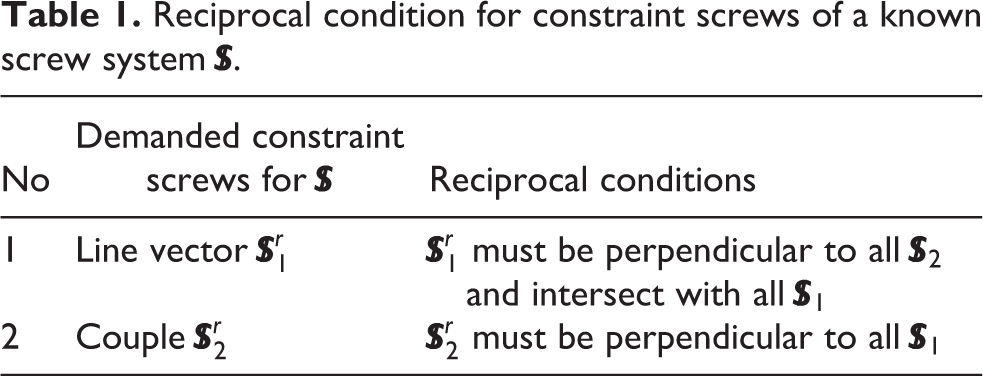
The reciprocal condition of constraint screws for a known screw system is summarized in Table 1, where
Reciprocal condition for constraint screws of a known screw system
The novel coupled model is expected to be an expandable and retractable mechanism with translational motion. Because of the only use of R-pairs, motion screw systems of the modified branches include line vectors merely. To avoid local or inactive DOFs for stability and effective mobility, the rule of adding the minimum components symmetrically is followed. As shown in Figure 6, an additional joint R5 is introduced by adding a component shown in Figure 3(a) to L
5 in branch 2 and the constraint force

Modified loop.
Structure description for the novel basic coupled model
As shown in Figure 7, the novel coupled model consists of two regular triangular components, that is, D 1 and M 1, and three square nodes, that is, N 1, N 2, and N 3, which are connected by 12 binary links with 21 R-pairs. R i (i = 1, 2, 3) are the R-pairs located on D 1, and those fixed on Nj are labeled as R j 1–R j 4 (j = 1, 2, 3). The three R-pairs for M 1 are R4k (k = 1, 2, 3) and the remainder three mid-joints are R q (q = 4,5,6), respectively. V = 21, F = 11, and E = 30 can be calculated for the coupled model, which satisfy equation (1) and demonstrate the reasonability of the novel mechanism.

Structure and motion flow of the novel basic coupled model.
The new loop N 1-R12-R6-R33-N 3-R32-R5-R23-N 2-R22-R4-R13-N 1 is located exactly in the symmetric plane π and the three symmetric lines O′N i (i = 1, 2, 3) pass through corresponding axes of mid-joints R q (q = 4,5,6), respectively. Hence, the symmetric relations for original model in Figure 4 also satisfy the modified coupled model in Figure 7. The initial configuration for the following mobility analysis is represented by the mechanism configuration at any time of the moving process in Figure 7.
Mobility analysis of the novel coupled mechanism
Mobility of a novel basic coupled mechanism should be analyzed primarily for further recognition. The improved method with independent motion shunting is valid for mobility analysis and output motion characteristics of the complicated multiloop coupled mechanisms. 24 In this section, the obtained coupled system is disassembled into three identical branches according to the method of motion shunting first. Then, the motions of the nodes are analyzed and expressed as simple generalized kinematic limbs. Finally, the complicated basic coupled model can be converted to an equivalent parallel mechanism. The mobility analysis of the proposed novel mechanism is illustrated in detail as follows.
Decomposition of the novel basic coupled model
Based on the motion shunting measurements, the designed coupled mechanism referred in Figure 7 is decomposed into three identical branches i, where i = 1, 2, 3. Each branch i has a node Ni , and the connection from D 1 to node Ni is Ci . The node Ni connects three subchains labeled Ci 1, Ci 2, and Ci 3, respectively, so Ci is expressed as Ci = Ci 1∪Ci 2∪Ci 3. In addition, two R-pairs R i 4 and R4i are located between Ni and M 1, and any branch i can be expressed as a chain of Ci -R i 4-R4i . In Figure 7, the motion flow of every branch is marked with red arrows and the corresponding sketch diagram is displayed in Figure 8. Taking C 2 as an example, Figure 9(a) to (c) shows the three subchains C 21, C 22, and C 23 enclosed in green dashed lines.

Sketch diagram of three coupled branches.
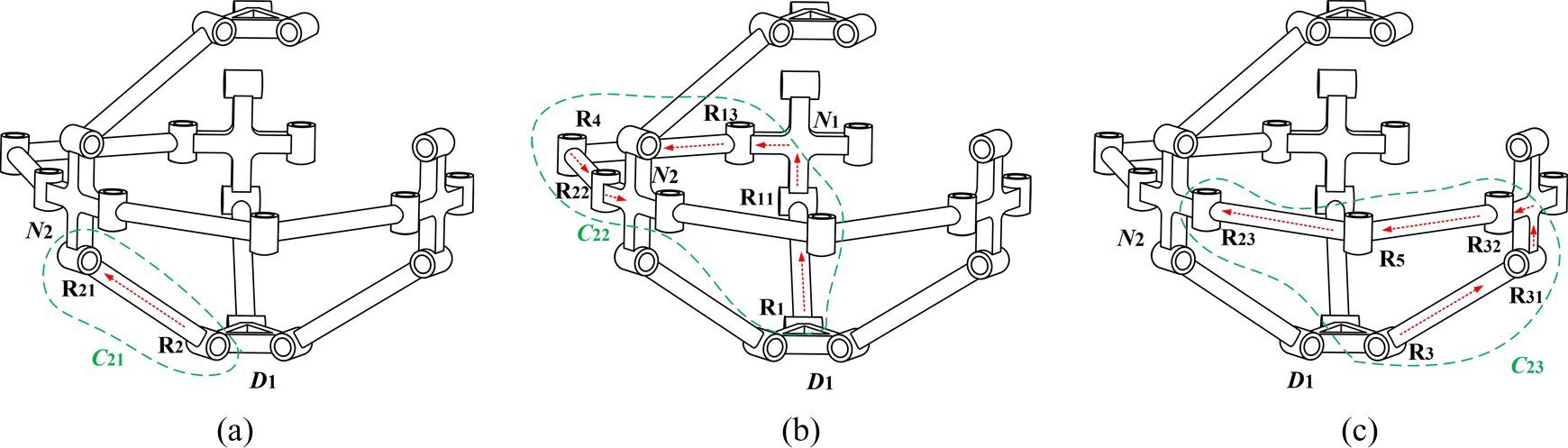
The three subchains of the branch 2: (a) subchain C21; (b) subchain C22; (c) subchain C23.
Mobility analysis of the mechanism
As illustrated in Figure 9, the three parallel subchains in the initial configuration can be indicated as C 21 (R2-R21-), C 22 (R1-R11-R13-R4-R22-), and C 23 (R3-R31-R32-R5-R23-). C 22 and C 23 are located symmetrically with plane 2, as shown in Figure 7. To analyze the constraints of each subchain, a local coordinate system Oc -XcYcZc in Figure 10 is built, where Yc -axis is along the direction of the R21-axis and the plane OcXcZc coincides with the symmetrical plane 2 of branch 2 aforementioned. Suppose that the midpoint of the R11-axis is A 1 (a 1, c 1,0), the direction vector of R31-axis can be denoted as A 2 (a 1,-c 1,0).

Coordinate systems for mobility analysis.
C2 mobility analysis
The screw system of the chain C 21 for the initial configuration in coordinate frame Oc -XcYcZc is

where d
1 and f
1 represent two elements of dual unit of
Then, the constraint screw system is obtained as

which indicates two constraint forces of
In the same coordinate system, the screw system of C 22 is expressed as

The corresponding constraint screw system will be

Equation (6) defines a constraint couple limiting the rotation of N 2 around the normal line of the plane defined by R11- and R13-axes.
The screw system of chain C 23 connecting with the same structure as chain C 22 can be obtained symmetrically
then the corresponding constraint screw system is

By solving the reciprocal screw system of the union set of equations (4), (6), and (8), we obtain

which demonstrates the secondary reciprocal screw system of the symmetrical double loop and illustrates an independent translation of N 2 relative to the base.
Mobility analysis of branch 2
As shown in equation (9), the motion of C 2 can be expressed as a prismatic pair P2, therefore, branch 2 can be equivalent to a generalized kinematic chain P2-R24-R42 and the motion screw system in Oc -XcYcZc is

then the constraint screw system is

where
Mobility analysis of the end effector M1
To describe the overall constraints acting on M 1, the global coordinate system O-XYZ shown in Figure 10 is established, where the origin O coincides with the projection of the geometrical center O′ on the base plane and the X-axis is perpendicular to R1-axis. Z-axis is vertical to the plane of D 1, pointing up to M 1, and Y-axis is along the direction of R1-axis.
Based on the identical constructions of the three branches and the symmetry planes shown in Figure 7, constraint sets from branch 1 and branch 3 exerted to M 1 are identical to that of the branch 2 expressed in equation (11). Hence, on the whole, the end effector will be restricted by three constraint forces and six constraint couples. The constraint screw system of all branches can be expressed in O-XYZ as

and the secondary reciprocal screw system is

Equation (13) shows that M 1 has one translation along Z-axis, indicating the reciprocating motion of the moving plane.
Mobility analysis of the equivalent parallel mechanism
Based on the mobility analysis of the end described in the previous section, the novel coupled mechanism can be converted to the equivalent parallel mechanism shown in Figure 11, which means the mobility of the coupled model can be calculated by that of the equivalent parallel structure.

Equivalent parallel mechanism.
It is well known that each generalized branch provides two constraint couples and a constraint force. There is a common constraint (λ = 1) among these constraint couples and the order of the mechanism is five (d = 6 − 1 = 5); the rank of the three linearly dependent constraint forces is two. There are two parallel redundant constraints overall, that is, v = 2, and the number of local DOF is zero, that is, ζ = 0. According to the modified Grübler-Kutzbach formula, 27 the DOF of the terminal mechanism (M), which is equal to that of the end effector (M 0), can be solved

The established local and global coordinate systems shown in Figure 10 are valid to analyze the mobility for the unchanged relationship of the relative motion and constraint characteristics of the three symmetrical branches throughout the moving process. Moreover, it is proved that the mobility analysis of the coupled mechanism is full cycle.
Kinematics analysis of the novel coupled mechanism
To investigate more advantageous characteristics of the designed structure, a kinematic module is established for solving the inverse kinematic solution based on the geometrical construction and symmetrical properties mentioned in section “Modeling of the novel coupled mechanism.” The work conducted in this section provides the basis for future work, such as dynamic analysis.
As far as a coupled mechanism concerned, the inverse kinematic analysis looks for the variable values of the actuator joints located on the base with given position and orientation of the end effector. To describe the relationship of the position for every connecting rod, the D-H, which is frequently used for studying parallel mechanisms, is adopted to define the geometrical parameters and joint variables in sequence. Note that the posture of the node has the same parameters for every chain, thus symmetry properties allow to simplify the calculation and kinematics analysis.
Establishment of coordinate systems
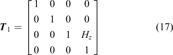
Based on the three symmetric planes, that is, plane 1, plane 2, and plane 3 as shown in Figure 7, only the branch 2 shown in Figure 12 is taken as example to perform the kinematics analysis in the initial configuration. To display the coordinate frames clearly, the branch 2 shown in Figure 12 is taken as example to perform the kinematics analysis in the initial configuration. The coordinate system O-XYZ, which is fixed on D 1 and built for the aforementioned mobility analysis, is the reference system. The midpoint of each R i -axis on D 1 is marked as Bi (i = 1, 2, 3) correspondingly. The side B 2 B 3 is perpendicular to the X-axis and parallels to the Y-axis. The origin of moving coordinate P-XpYpZp is attached to the center of M 1, where Xp -axis is parallel to X-axis and Zp -axis coincides with Z-axis. The midpoint of each R4j -axis on M 1 is labeled as Ej (j = 1, 2, 3). The line connecting the origins of O and P passes through the center O′. The point P located on the end effector is selected as the reference point and its spatial position coordinate is expressed as (0, 0, Hz ) in O-XYZ for one translational DOF.

The coordinate systems of branch 2.
Each subchain C 2i (i = 1, 2, 3) for branch 2 in Figure 9 can be viewed as a linkage composed of a series of R-pairs. Axes Zij (i = 1, 2, 3; j = 0…7) of each joint marked with red dashed lines in Figure 12 represent the jth joint of the ith subchain for the branch 2, where corresponding coordinate systems located at joints are set to describe the spatial position transformation of adjacent links. Considering that the axis of R6 is located in the symmetric plane 2 and passes through the O′N 2, the kinematical analysis of the subchain C 22 can be deduced by that of C 22. Then, the D-H models of C 21 and C 23 are established as shown in Figure 13(a) and (b), respectively.
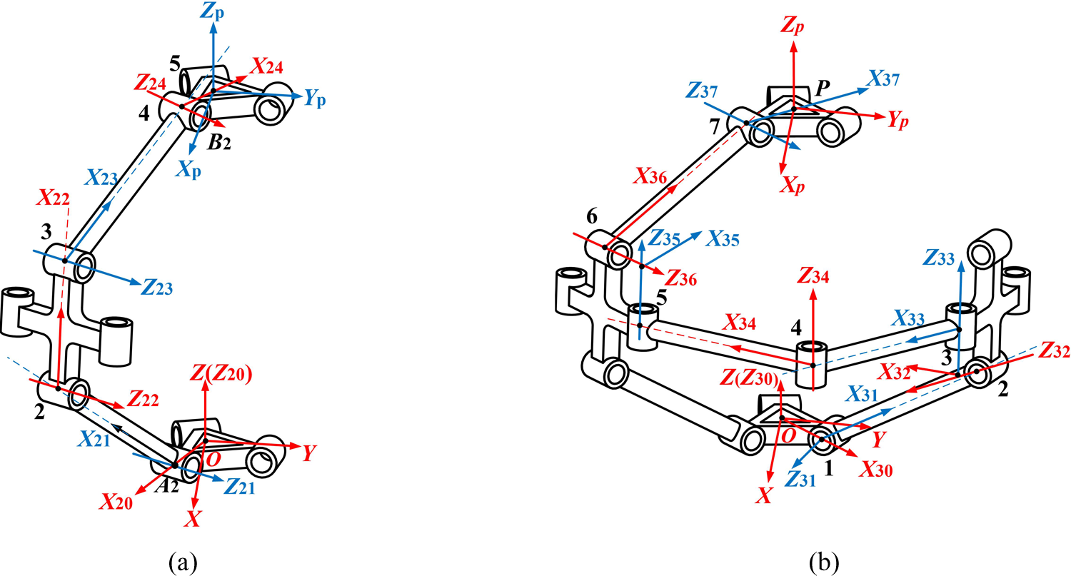
Coordinate systems attached to joins: (a) subchain C 21; (b) subchain C 23.
Kinematic mathematic model for C 21
The position of N 2 is determined by the comprehensive effects of C 21, C 22, and C 23, hence, the kinematic equations for different subchains with equal parameters at N 2 should be obtained.
By means of the 4 × 4 homogeneous matrix tool that describes the geometrical rotation and transformation relationship between two directly connecting bars, the transformation matrix for subchain C 21 from (i-1)th bar to ith bar is defined as

where αi −1,i is the torsion angle about Xi −1-axis from Zi −1-axis to Zi -axis, ai −1,i is the translational distance along Xi −1-axis from Zi −1-axis to Zi -axis for the length of the (i − 1)th bar, di is the offset distance along Zi -axis between Xi −1-axis and Xi -axis, θi is the joint angle around the Zi -axis from Xi −1-axis to Xi -axis.
Referring to Figure 13(a), Table 2 lists the D-H parameters for C 21 with the established coordinate systems. The transformation of C 21 from the base to the end effector is shown in Figure 14(a) and that of C 23 is shown in Figure 14(b).
D-H parameters for chain C 21.


Geometrical transformation relationship with D-H parameters: (a) chain C 21; (b) chain C 23.
Hence, the corresponding transformation matrix for chain C
21 labeled

where
and the D-H transformation matrixes in equation (16) can be written with parameters in Table 2 as
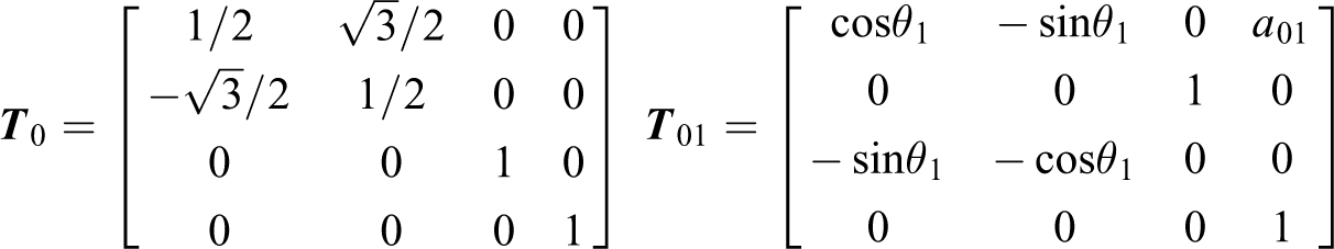


Then, the transformation for C 21 is converted to the equivalent kinematical equation. Considering the geometrical dimensions of designed components, following relationships can be obtained

where h 1 is the length of the connecting line between the origin O and the point B 2, and h 2 is equal to half of the distance of parallel axes of Z 22 and Z 23. The symbol L indicating the length of each connecting bar and rj (j = 1, 2) meaning the radius of axis hole for R-pairs of regular triangle parts and square nodes, respectively, are design parameters of all substitutive components that will be given for the simulation model in section “Numerical validation and simulation analysis.”
By substituting equation (19) into equation (18), the position of the end effector for C 21 can be accomplished by equating both sides of equation (16) and simplified as

Note that θi assumes a positive or negative sign depending on the configuration of the chain. With regard to the inverse kinematic analysis, the actuator variable θ 1 and other joint angles θi can be acquired once H z for the initial position of the moving plane is given, which yields

Finally, the variables of the actuator and other joints in C 21 are solved.
Kinematic mathematical model for C 23
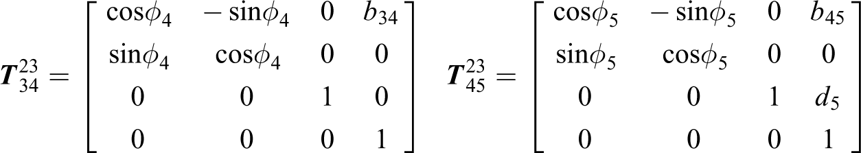
The inverse kinematic analysis for C 23 can be carried out with the same reference system and moving system shown in Figure 12. To distinguish the D-H parameters of C 21, different symbols with the same meaning for C 23 are used to express the transformation matrix as
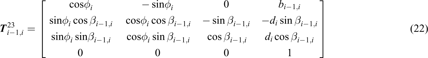
where φi is the joint angle around the Zi -axis from X −1-axis to Xi -axis, βi −1,i is the torsion angle about Xi −1-axis from Zi −1-axis to Zi -axis, bi −1,i is the translational distance along Xi −1-axis from Zi −1-axis to Zi -axis for the length of the (i − 1)th bar.
The corresponding geometrical transformation of all joints for C 23 has shown in Figure 14(b) using parameters in Table 3.
D-H parameters for the chain C 23.

The relative transformation matrix for C
23 labeled as

where


the geometrical relations of D-H parameters for C 23 are

where h 1, h 2, and L have the same meaning as in equation (19).
Based on the constraint conditions of laws of sine and cosine, by substituting equation (25) into equation (24) and expanding equation (23) yield

Then, the variable φ 1 and other parameters for inverse kinematics analysis of C 22 can be implemented conveniently by symmetry; for space limitations, further details are not given. Solving equation (26), the variables for C 23 are determined when the initial position is known

Theoretical investigation of the inverse kinematic analysis of the presented coupled mechanism is carried out with the algebraic method. The variables of joint angles, θi and φj , can be determined if the position for the end device is given. In the next section, a numerical simulation is performed to validate the correctness of the mobility and kinematics analysis.
Numerical validation and simulation analysis
To verify the theoretical kinematics analysis, a numerical example is presented first. Then, a simulation model is evaluated to identify the synthesized manipulator and associated theoretical motion characteristics.
Numerical example
The dimensions of the parts composing the novel mechanism are listed in Table 4, where the symbol li (i = 1, 2, 3) is the edge length of corresponding components and rj (j = 1, 2, 3) is the radius of axis hole for R-pairs.
Parameters of substitutive parts.

The initial position of the moving plane is set to (0, 0, 36.45) in the overall coordinate system O-XYZ. Based on equations (21) and (27), the corresponding D-H parameters for C 21 and C 23 are shown in Tables 5 and 6, respectively.
D-H parameters for chain C 21.

D-H parameters for chain C 23.

The inverse kinematic results listed in Tables 5 and 6 reveal the symmetry of the initial configuration. Positive sign indicates counterclockwise rotation of each joint angle and negative sign stands for clockwise rotation. Then, substituting the parameters into equations (16) and (23), the transformation matrixes
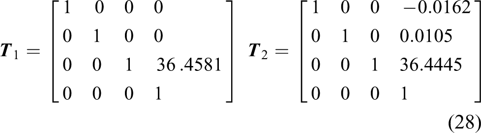
which indicate the relationship between the moving plane and the end effector. It is obvious that the inverse kinematic analysis including coupled chains by algebraic method is feasible. The main source of the errors in equation (28) is rounding.
Motion simulation for kinematic analysis
To investigate the motion characteristics of the new mechanism, the displacement variations of end and nodes, and joint angles of connecting links are simulated with a given rotational actuator. Motion properties are illustrated clearly by the curves of simulation results. Then, the correctness of theoretical motion analysis and symmetrical property are further verified.
Simulation model and driving condition
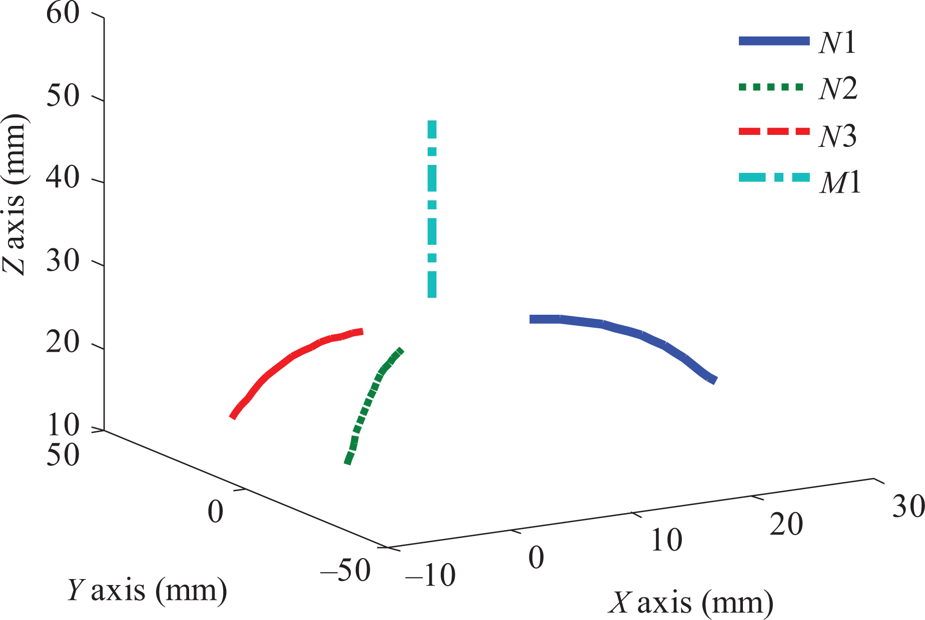
The three-dimensional model for simulation analysis established by the software SolidWorks 2013 is shown in Figure 15. The identical design parameters for the given numerical example listed in Table 4 are used for the following simulation. An actuator of rotational motor at 10 rpm marked with a red rotation arrow is mounted on R3-axis to realize one translation of reciprocal motion for end. The position variations of moving plane and nodes are determined by the overall coordinate system O-XYZ mentioned in Figure 12.

Simulation model.
Simulation of displacement variation
The simulation of displacement variations of moving plane and three nodes is implemented by means of the point P and the three centers of N 1, N 2, and N 3 in the global system O-XYZ. The motion simulations of the four measuring points along the three axes are carried out running the motor for 4 s. The corresponding range of the displacement of the end is from 30.0416 mm to 51.3406 mm, divided into 17 steps each lasting 0.25 s.
To show the mobility characteristics of M 1, time–displacement curves of the end along the three axes are plotted in Figure 16.

Motion simulation of M 1 along X-, Y-, and Z-axis.
Figure 16 shows that the translation along X-axis (black solid line) remains unchanged with time, as Y-axis (red dashed line) does, and the translation of Z-axis (blue dashed line) rises gentle. Therefore, the moving plane just has translational motion along Z-axis, so the feasibility of the novel coupled mechanism and the correctness of theoretical mobility analysis in section “Mobility analysis of the novel coupled mechanism” are demonstrated.
To highlight the symmetrical motion characteristic of N 1, N 2, and N 3, the displacement of each node along the same axis is plotted in a graph simultaneously for comparison.
The comparison of the plots in Figure 17 highlights that the displacement variation of N 1 is confined in the plane XOZ, which also represents the plane 1 shown in Figure 7. The variations of the three nodes along Z-axis keep the same during the whole simulation. Figure 18 shows that N 1, N 2, and N 3 exhibit good characteristics of radial motion tendency directing forward to geometrical center O′ with associated reciprocal translation of M 1 along Z-axis.
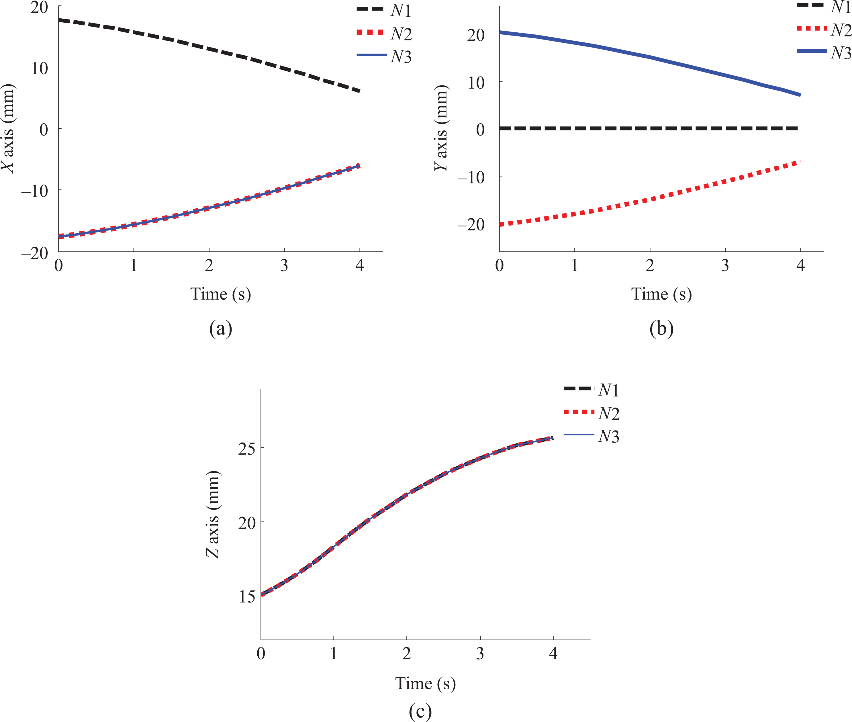
Motion simulations along the three axes for nodes N 1, N 2, and N 3: (a) X-axis; (b) Y-axis; (c) Z-axis.
Spatial displacement variations for components.
Based on the aforementioned simulations, the novel coupled mechanism synthesized symmetrically is proved to be a deployable mechanism. The expandable and retractable configurations of moving plane relative to the base are shown in Figure 19.

Different configurations: (a) retractable configuration; (b) expandable configuration.
Simulation for kinematic verification
In this part, the theoretical inverse kinematical results are verified with the simulation model. First, using the same displacement interval (from 30.0416 mm to 51.3406 mm, time length of 4 s), the value of each joint angle θi (i = 1, 2, 3, 4) in C 21 can be obtained by simulation. Compared with simulated results, according to Figure 20, the relationship among these angles can be illustrated in a Cartesian plane coordinate where the variation of θ 1 (cyan solid line) and θ 4 (black dashed line) overlap and decrease. On the contrary, the angles of θ 2 (red thick dot dashed line) and θ 3 (blue dashed line) overlap but have positive trend, thus the sum of angles θ 1 and θ 2 or θ 3 and θ 4 is always a constant value for negative 90°.

Joint angles of chain C 21.
The joint angles for C 23 are simulated with the same period of 4 s. Figure 21 shows the relationship among obtained joint angles, and the particular relationship of joint angles between C 21 and C 23 is shown in Figure 22.

Joint angles of the chain C 23: (a) comparison of φ 1, φ 2, φ 6, and φ 7; (b) comparison of φ 3, φ 4, and φ 5.

Comparison of joint angles of C 21 and C 23: (a) θ 1, φ 1, θ 2, and φ 2; (b) θ 3, θ 4, φ 6, and φ 7.
From Figures 21 and 22, the following relationships for simulated joint angles are established


Aforementioned relationships satisfy the kinematic mathematic model of section “Kinematics analysis of the novel coupled mechanism” and demonstrate the properties of symmetry of branch 2. The simulation results also prove that the whole coupled polyhedral mechanism is arranged spatially so that its plane of symmetry corresponds to π.
Conclusions
A novel symmetrical coupled mechanism based on a regular triangular bipyramid with elementary loops is proposed. The proposed mechanism is based on providing three types of new-design substitutive components for the edges and vertexes of the selected semi-polyhedron. The movable unit loop is modified by adding chains. The basic coupled model can be established by implanting the movable unit to the polygonal face of a regular triangular bipyramid. The mobility analysis based on screw theory demonstrates the new coupled mechanism with a translational DOF is feasible.
Then, the inverse kinematic of the coupled structure is analyzed based on its symmetry property. A numerical example is carried out with given conditions to verify the correctness of the theoretical analysis results. The relationship of these solved joint angles for each subchain is shown and the symmetry of the novel mechanism has been proved.
Finally, a simulation model is established to illustrate the properties of the motion. According to the displacement variation of end and nodes, the polyhedral manipulator is proved a deployable mechanism with one reciprocal translation accompanied by radial moving tendency of nodes toward the geometrical center. The fixed base and the moving plane always arrange symmetrically to a plane during motion.
The novel mechanism put forward in this article can not only enrich the variety of the polyhedral structures but also provide basis theory for synthesizing more kinds of symmetric coupled mechanisms. The presented mechanism may be considered as the execution structures of deployable mobile robots, and more wide studies, such as parameter optimization, prototype experimental research, application research, and so on, and serviceable applications of the polyhedral coupled mechanism should be explored in the future section.
Footnotes
Declaration of conflicting interests
The author(s) declared no potential conflicts of interest with respect to the research, authorship, and/or publication of this article.
Funding
The author(s) disclosed receipt of the following financial support for the research, authorship and/or publication of this article: The authors are grateful to the project (No. 51475015) supported by NSFC, the open project (No. 310825151130) of National Engineering Laboratory for Highway Maintenance Equipment (Chang'an University).