
Abstract
This article focuses on the forward kinematic analysis of a class of asymmetrical parallel manipulators by the proposed elimination approach. To solve the key forward kinematic constraint equations with transcendental parameters of the manipulator, an improved elimination algorithm is presented. First, by analyzing the geometry structure of the manipulator, we find the inherent triangular-topology relations of the manipulator. Further, by utilizing the parameter transformation of angular, the key transcendental equations of forward kinematic analysis are formulated into compact polynomial ones. In this context, comparing with the screw approach by Gallardo-Alvarado suggested that the computation efficiency of our proposed approach is superior. Finally, an example of the asymmetrical variable geometry truss manipulator illustrates the effectiveness of the proposed approach.
Keywords
Introduction
Forward kinematics is a primary problem for the concept design and analysis of asymmetrical parallel manipulators (PMs). As a representative of asymmetrical PMs, asymmetrical variable geometry truss (VGT) manipulators have received a great deal of attention due to their inherent advantages over the conventional PMs, and these advantages involved simpler structure, higher stiffness, safer device, and had been gained in potential applications. 1
As far as most asymmetrical PMs, the key problem of forward kinematic analysis (FKA) is concluded as two aspects: establishing the main kinematic model in its structure topology and solving the main equations in its kinematics mechanism. In the last few decades, the FKA of asymmetrical PMs had stimulated the interest of many researchers. 2 –15
On the one hand, to set up the main kinematic model of PMs, several geometrical methods 4 –11 are introduced. As early as in 2002, Tsai and Joshi 12 investigated a hybrid kinematic machine by defining the notion of modular. In additional, the authors addressed that geometry centers of the modular can be reconfigured in series or parallel, but the machine did not provide the norm orientation of the platform so as to have trouble in analyzing complex or parasitic motions with more freedom. Further, Ceccarelli et al. 3 presented a more suitable model through utilizing natural coordinates of suitable points and vectors. Because of the considered model without using any angular variables, forward kinematics are easier obtained via determining position and orientation of geometry centers of the model. Such a method is applied broadly, but it is inadequate for velocity and acceleration analysis. Extending this work, Correa and Crane 4 put forward the forward and reverse analyses for a three-degree-of-freedom (DOF) compliant platform by using compliant joints referred to the velocity of the moving platform and the velocity of the actuators.
Recently, the theory of screws for PMs had been applied widely in displacement, workspace, velocity, and acceleration analyses. For instance, Gallardo-Alvarado et al. 5,6 presented forward displacement analysis (FDA) of a serial PM with two asymmetrical limited-DOF PMs 7,8 assembled in series connection. But the FDA approach is merely adapted in a limited DOF of PMs. Further, Zhao et al. 9 developed a tetrahedron coordinate algorithm only by utilizing four noncoplanar points’ coordinates of the end effector to build up the linear kinematics model of a spatial PM. The advantage of this algorithm is explicit when establishing the kinematics models for complex spatial PMs with three to six DOFs.
However, the above-mentioned methods may be not applied directly to certain asymmetrical PMs with more DOFs, since the number of investigated points will be increased vastly when there is a slight increase in DOFs of the manipulators. As a result, too many variables lead to calculation of collapse.
On the other hand, in the solution of FKA problem for asymmetrical PMs, it is inescapable to generate nonlinear kinematic constraint equations which led to multiple solutions. 10,11 To obtain an interesting solution, several algebraic methods 12 –15 are introduced to solve the main nonlinear kinematic equations with its kinematic model. Griffis and Duffy 12 and Innocenti and Parenti-Catelli 13 derived a 16th degree univariate polynomial on the general 3-6 Stewart platform. But the approach is considered as only closure configurations in the complex field. Further, Dhingra et al. 14 used Gröbner–Sylvester hybrid method to obtain a 20th degree input–output polynomial directly from the 15 × 15 Sylvester’s matrix. Moreover, to yield a unique current solution, Kong et al. 15 represented a new FDA approach for a linearly actuated quadratic spherical PM by formulating the kinematic equations.
But to the best of our knowledge, the mentioned approaches of solving nonlinear equations are very difficult to avoid the occurring of transcendental functions in the FKA. Here, taking consideration of the key nonlinear kinematic equations with some unknown transcendental parameters, the solution of FKA for asymmetrical PMs may be in a nonunique form or an interesting solution (singularity) loss of kinematic performance at its spatial configuration. Therefore, it is of significant to obtain a good solution by changing the original equation into a univariate polynomial equation. Furthermore, how to deal the class of equations with some transcendental parameters in maintaining the performance of the kinematics mechanism is still an open problem.
In this article, the FKA of the asymmetrical PM is investigated by means of the proposed elimination approach. First of all, by comparing with the topology structure of the manipulator in the studies of Williams 17 and Gallardo-Alvarado et al., 19 we reveal the inherent geometrical triangular-topology relations. Secondly, the key transcendental equations of FKA are transformed into compact polynomial ones by selecting some suitable angular parameters from the transformed function proposed. Further, a modified elimination algorithm is utilized to solve the key constraint kinematic equations of the manipulator. In this context, the computation efficiency of the proposed approach is higher than the screw approach of Gallardo-Alvarado et al. 19 Finally, a numerical example of the VGT manipulator is provided to illustrate the effectiveness of the proposed approach.
This article is outlined as follows. In the next section, the FKA of a class of asymmetrical PMs (VGT) mechanism is discussed. “The elimination approach for the FKA problem of the asymmetrical PM” section is devoted to using the improved elimination approach to solve for the FKA problem, and the simulation result is shown in “Simulation” section. The conclusion is drawn in the final section.
FKA of a class of asymmetrical PMs
Description of the asymmetrical manipulator module
Taking into coordinate transformation account for traditional approaches of kinematic mechanisms, the actual pose, position, and orientation of the moving platform are determined with respect to the fixed platform. At first, we give the geometry structural description of the manipulator module. As shown in Figure 1, the standard single module for a class of asymmetrical PMs is a relative independent one as a triple octahedron, and then, the whole manipulator is connected by combined plane (such as the mobile platform referred to center O2).
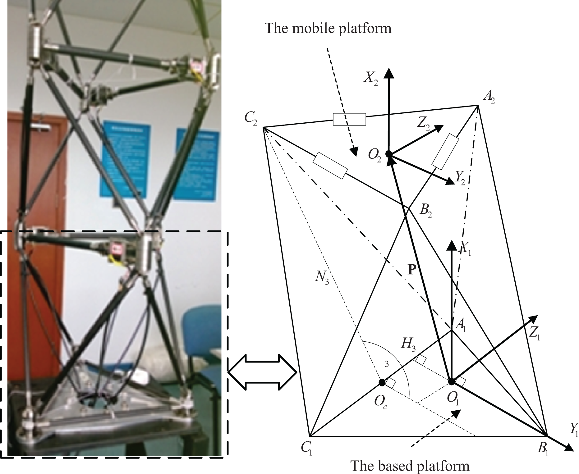
The single module of asymmetrical PM for the Stewart platform analogy. PM: parallel manipulator.
In our discussion, each typical single module includes two triangular platforms which are adjacent to six fixed links. Here, different from symmetrical Stewart platform
18
or asymmetrical Stewart platform,
19
the manipulator is assumed to be a statically determinate truss.
20
Specially, a three-DOF asymmetrical PM is designed in the following. (1) As three points of a fixed triangle (2) As three points of an arbitrary triangle (3) In general, the triangle (4) For the convenient of analysis, the absolute frame system
Forward kinematic problem for single asymmetrical PM module
Given the lengths of fixed links for a class of asymmetrical PMs, corresponding to the conditions of constraint length of each virtual links Li (implied two-norm distance conditions in the study of Williams
17
), the kinematic constraint equations of joints


where the dot ⋅ denotes the inner product of the usual three-dimensional vectorial algebra. It states that

where P denotes the norm vector distance from original point O1 to point O2 for the single module.
From equations (1) to (3), the position center vector
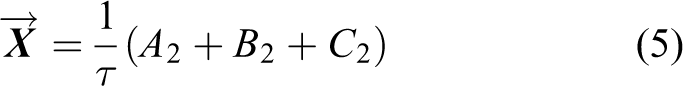
where the value of
Since the position vector

where

In practice, the essence of the FKA problem of the asymmetrical manipulator is to find the geometry center of position vector and orientation vector at the mobile platform via designing several controllable parameters related to angular
Space position of joint center A2 in the absolute frame system
Here, joint center A2 will be first given in a set of generalized coordinates by introducing certain auxiliary lines as shown in Figure 2. To simplify the complexity of constituting auxiliary lines, we recreate a reference frame system

Space position of joint center A2 in the absolute frame system
First, if the original center O1 is located at the orthocenter of the based platform, Y1-axis is defined by keeping the same orientation as the vector
Second, in the absolute frame system
Third, the point Oa is taken to be the midpoint of line A1B1, and then, an auxiliary line A2I1 (paralleled with X1-axis) is produced by passing through the vertex A2 and being orthogonal to the bottom triangle ΔA1B1C1 at point I1 which falls into the extension line E1Oa (paralleled to Z1-axis).
The angle expression of joint center A2 in the absolute frame system
From Figure 2, once given the coordinates of points
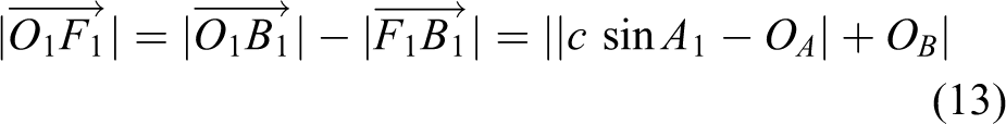
Step 1. Determining the coordinates of points H1, F1 in the new absolute frame system
From the coordinates of points E1, Oa displayed in Figure 3, there are the pedals H1, H2, and H3 located on sidelines A1B1, B1C1, and A1C1, respectively. On one hand, since the bottom platform is regarded as a fixed triangle, thus all angles

The coordinates of points E1, Oa in the absolute frame system
Therefore, two right-angled triangles

In

and further, the vector
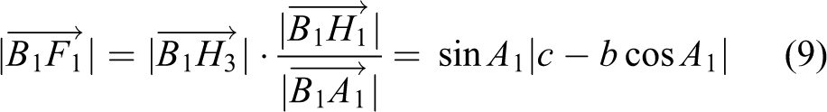
Concerning the collinearity of three joints A1, H3, and C1, one has

In

For simplicity, let

From equations (9) to (12), we obtain
where
Since

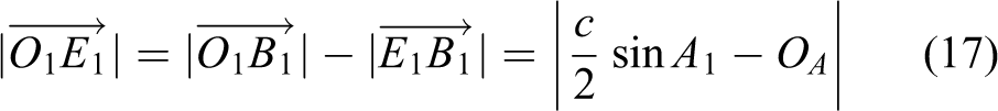
Step 2. Figuring out the coordinates of points E1, Oa in the absolute frame system
From step 1, the auxiliary line OaE1 passed through midpoint Oa at Y1-axis is orthogonal to line B1H3, and we obtain
Substituting equations (7) and (8) into equation (14), one gets

Substituting equations (7) to (9) into equation (14), one writes

Subtracting equation (16) from equation (12), the vector
Further, by observing from equations (15) to (17), the coordinate of point Oa is represented as

Step 3. Calculating the coordinate of point I1 in the absolute frame system
To build up an angle formula of point I1, geometry relationships of the lateral triangle

Geometry relationships of the lateral triangle
In
for
Based on the definition of the cross longeron face angle, the angle θ1 can be stated as the angle E2OaA2, as shown in Figure 2. In

and

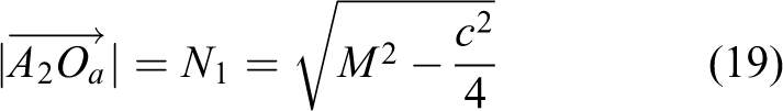
Arranging from equations (15) to (21), the length of the vector

Subtracting equation (17) from equation (22), the coordinate of point I1 is unfold as
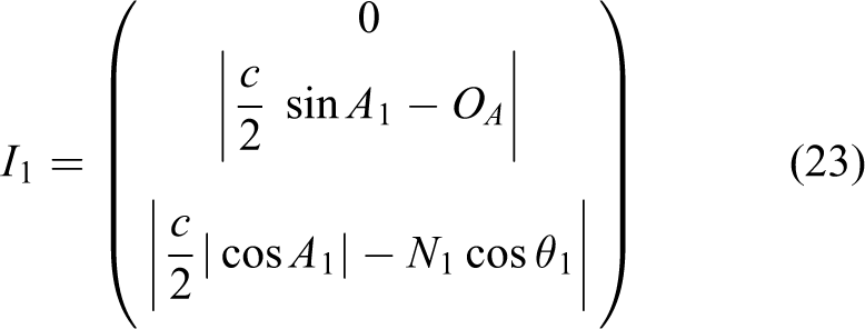
Step 4. Providing the coordinate of points A2 in the absolute frame system
Once equations (20) and (23) are held, then the coordinate of vertex A2 will be yielded as

where
Therefore, the angle expression of the joint vector A2 can be stated as

For the purpose of understanding well the context of this article, the derivation process of the coordinates of two vertexes
The elimination approach for the FKA problem of the asymmetrical PM
Description of the elimination process
For most PMs, there are always multiple solutions of the forward kinematics. An algebraic elimination method 18 is adopted to search the correct and feasible solution from multiple solutions of the FKA problem.
When the angle expressions

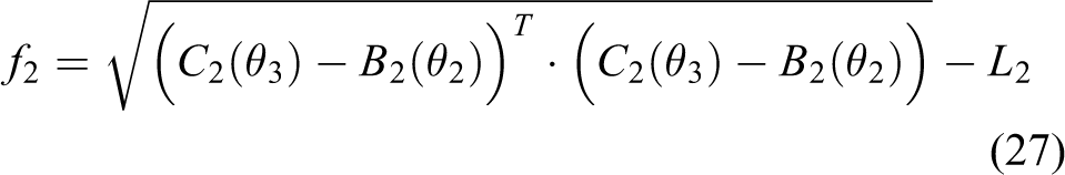

Naturally, we will acquire several transcendental equations with angular parameters θi, if these equations (26) to (28) are expanded thoroughly. But the derivation of solution of transcendental equations is complex and difficult as usual. Here, by utilizing the algebra elimination process, we give some of angular parameters transformation formulae, and thus, these transcendental equations (26) to (28) are transformed into such compact polynomial equations with 12th degree as


where some angular parameters si and ci are substituted by the scalar
Proof
See Appendix 3. □
The improved elimination algorithm for the FKA problem
Throughout the strategy for the geometry auxiliary line analysis, all the feasible locations of the mobile platform, with respect to the based platform, are able to be computed by giving a set of generalized coordinates, if the kinematic constraint equations (29) to (31) are solved. In the studies of Wu and Huang 16 and Huang et al., 18 an improved elimination process is presented.
The improved elimination algorithm is as follows:
Step 1. Initialize
Step 2. Establish geometry relationships of parameters
Step 3. Extract angle expressions of joint points
Step 4. Derive compact polynomial equations (29) to (31) by transforming from transcendental equations (26) to (28).
Step 5. Solve equations (29) to (31) by using algebraic elimination process to make angular parameters be iterative, and further find a feasible or an interesting solution from multiple solutions with constraint conditions of lengths of the actuators (
Step 6. Compute the coordinates of joint vectors
Step 7. Give the position vector P from equation (4).
Step 8. Obtain the position vector
Step 9. Update
In a nutshell, the forward kinematic problem for single module of the asymmetrical manipulator is solved by using the proposed elimination approach. The algorithm is of global convergence if a desired initial value is demanded in such an iterative process, and further, a feasible or an interesting solution should be close to the solution of the current expected configuration.
Simulation
The purpose of this simulation experiment is to synthetically verify the improvement in computational efficiency using polynomial equations by the proposed elimination algorithm instead of transcendental ones used by Gallardo-Alvarado et al.
19
In our discussion, the forward kinematics of the asymmetrical PM (chosen VGT manipulator) is to present the center position vector
In the framework of the improved elimination algorithm, the experiment setup is presented as follows. When the initial parameters are given in Table 1, a forward kinematic of VGT manipulator is utilized to calculate the vectors of the vertexes of platform. Further, by utilizing the parameter transformation of angular, the polynomial equations of forward kinematic are used to solve for the vertexes. Without loss of generality, the model dimension parameters of the manipulator are consistent with physical prototypes. The specific simulation parameters are recorded.
In this experiment, by analyzing the suggested elimination algorithm, steps 2 to 4 will be calculated on off-line, and the results are saved in the prescribed path so as to analyze conveniently in the next step. In step 5, substituting equations (29) and (31) into equation (30), when we choose x1 defined as a fixed variable (x = x1) as shown in Appendix 3, the key compact polynomial equations (29) to (31) are converted as a fourth univariate polynomial with a unknown variable x

where ap,
For the purpose of proving the following two conclusions: The improved elimination algorithm is reasonable. There is indeed an improvement in computational efficiency by employing polynomial equations instead of transcendental ones.
Selecting the same initial parameters as in Table 1, we compare two approaches in variables
Parameters of VGT physical prototype.

VGT: variable geometry truss.
Here, t is called the consumption time of the algorithm, which is also regarded as elapsed times of the computer, when the program for one of two approaches runs once. It is calculated as

where the number KN is taken to be the number of solutions of the forward kinematics.
As shown in Table 2, by computing formula (33), the average consumption time of the screw approach of Gallardo-Alvarado et al. 19 and the improved elimination algorithm is 4.03437 s and 3.4699 s, respectively. In other words, the computation efficiency of the latter approach is increased by 16.27% than the former one.
The comparison of several main parameters between the proposed approach and the screw approach of Gallardo-Alvarado et al. 19

Additionally, by inspection of the coordinate values referred to as the variable
Therefore, the simulation experiment has verified that the improved elimination algorithm in this article can effectively make up for the shortcomings of the large amount of computation in the study of Gallardo-Alvarado et al. 19,21 The scheme may be a feasible one to implement mechanics or dynamics analysis of the manipulator in the future.
Conclusions
In this article, we emphasize on an improved elimination algorithm with improving computational efficiency, after analyzing the geometry relationship of triangular-topology structure for a class of asymmetrical PMs and applying parameters transformation to the forward kinematics. Further, compared with the screw approach by Gallardo-Alvarado, 19 the computation efficiency of the proposed approach is improved by 16.27%. Finally, an example of the VGT manipulator is given in order to prove the efficacy of the proposed method.
Footnotes
Acknowledgements
The authors are grateful to the anonymous reviewers for their helpful comments.
Declaration of conflicting interests
The author(s) declared no potential conflicts of interest with respect to the research, authorship, and/or publication of this article.
Funding
The author(s) disclosed receipt of the following financial support for the research, authorship, and/or publication of this article: This article is jointly supported by the Natural Science Foundation of China (61175028 and 61374161) and the Key Project of Natural Science Foundation of Shanghai (16JC1401100).
Appendix 1
The derivation process of the angle expression of the vertex B2 is shown as follows.
Main derivation process: Here, joint center B2 will be given in a set of generalized coordinates by constituting several proper auxiliary lines in the reference frame system
From Figure 5, several auxiliary lines positioned the coordinate of points E2, Ob, and I2 are given with the cross longeron face angles θ2. The detail derivative of auxiliary line analysis will be represented by the following fourth steps:
Step 1. Providing the coordinate of points H2, F2 in the absolute frame system
On the one hand, the coordinate of points E2, Ob displayed in Figure 6 are consistent with respect to the same geometry positions as drawn in Figure 5, since the auxiliary lines of construction are not altered at the plane of
From Figure 6, if the original point O1 located at the orthocenter of
Because of the vector
Taking consideration of collinearity of three joints A1, O1, and H2, one writes
Let
and
By combining equations (36) and (37), the coordinate of point H2 is expressed as
Step 2. Figuring out the coordinate of points E2, Ob in the absolute frame system
Since Ob is the midpoint of sideline C1B1, and five points B1, H2, F2, Ob, and C1 are collinear, then the vector
Since
where
In
Moreover, the vector
where
Since three points B1, E2, and F2 are colinear, and once equations (40) to (42) are held, one obtains
where
On abstracting equations (37) and (43) into the vector
Let
where HA, HB, and HD can be seen in equations (36), (40), and (43), respectively.
Step 3. Calculating the coordinate of point I2 in the absolute frame system
In Figure 6, several auxiliary lines are established. For instance, a line ObU1 paralleled to Y1-axis is plotted by intersecting with the line A1C1 at point U1. Since
and thus, the quadrilateral
In
As shown in Figure 7, we have
According to the angle bisector theorem,
and
From the Pythagorean theorem, the height line from vertex A2 to a base platform in
What’s more, since three joints E2, Ob, and I2 are collinear, and once equations (40) and (50) are held, the vector
where
Considering equations (44) and (52), the coordinate of point I2 can be expressed as
Step 4. Determining the coordinate of points B2 in the absolute frame system
Substituting equation (51) into equation (53), the coordinate of vertex B2 will be measured as
where IA, IB, HA, and HD can be seen in equations (44) and (53), respectively.
Further, the angle expression of the joint vector B2 can be stated as
Therefore, the derivation process of the angle expression of the vertex B2 is completed. □
Appendix 2
Here, the derivation process of the coordinates of the vertex C2 will be ignored for the sake of brevity. For the purpose of understanding well the context of this article, the specific angle coordinates of joint vectors
where
Appendix 3
The derivation of polynomial equations (29) to (31) is shown as follows. To make transcendental equations (26) to (28) be formulated by using the parameter transformation of angular, some angular parameters are selected as