
Abstract
The article deals with development and application of snake robot for inspection pipes. The first step involves the introduction of a design of mechanical and electrical parts of the snake robot. Next, the analysis of the robot locomotion is introduced. For the curved pipe, potential field method is used. By this method, the system is able to generate path for the head and rear robot, linking the environment with obstacles, which are represented by the walls of the pipe. Subsequently, the solution of potential field method is used in inverse kinematic model, which respects tasks as obstacle avoidance, joint limit avoidance, and singularity avoidance. Mentioned approach is then tested on snake robot in provisional pipe with rectangular cross section. For this research, software Matlab (2013b) is used as the control system in cooperation with the control system of robot, which is based on microcontrollers. By experiments, it is shown that designed robot is able to pass through straight and also curved pipe.
Introduction
A pipe inspection task is an often performed operation, which is done using a broad spectrum of robotic systems based on wheeled chassis, tracked chassis, bristled robots, or snake robots. Development of snake robots started in 1970s by Prof. Shiego Hirose. Idea of designing snake robots comes from nature and mainly because of the high-level of flexibility of snakes to their environment. High degrees of freedom (DOF) enables this kind of mechanism to be more adaptable to its rough terrain and environment. 1
A considerable amount of snake robots were developed until now, with lateral undulation locomotion using passive wheels, which represent or simulate repulsion of robot from an obstacle. 2,3 Our study concerns snake robot without any wheels, wherein its forward motion is enabled using contact forces with walls of the pipe.
Up to now, several snake robots were developed for the purpose of pipe inspection. Wakimoto et al. 4 studied the inspection of pipe using micro snake robot. The aim of the article was to develop snake robot that would be able to pass through the pipe by overcoming the changing diameter of the pipe. The principle of locomotion is based on generating sinusoidal curve by snake robot. This research also deals with stabilization of camera mounted on the head link. Fjerdingen et al. 5 developed snake robot with active wheels with which it is able to pass through the horizontal and vertical pipes. Robot serves in inspection, maintenance, and repair of a diverse set of pipes and pipe-like structures. A two DOF snake robot that is able to pass through straight and curved pipe is developed in this work by Brunete et al. 6 However, this work doesn’t offer mathematical background of the proposed locomotion patterns. Maneewarn and Maneechai 7 studied the parameters that contribute to the crawling performance of the snake robot inside an inclined pipe. The authors tested several types of curves for locomotion in the pipe. The work 8 presents the influence of fixation curves by which snake robot can be fixed in the pipe using concertina locomotion. Everist and Shen 9 deal with mapping of a robot environment in the pipe. Authors proposed techniques for (1) pose estimation of a snake robot using a self-posture motion model, (2) correcting error in pose estimation using only the snake’s internal configuration overtime, and (3) building environmental features using only self-occupancy and contact detection. Concertina locomotion was also used in the study by Trebuňa et al. 10 The developed snake robot, LocoSnake, has unique kinematic configuration which uses one revolute and one prismatic for each link.
Based on the study of previous works on snake robots moving in the pipe as well as based on our own research in this area, our research team continue with the development of new snake robot that would able to take the nonnature kind of locomotion and also able to overcome both straight and curved pipes. The article is organized as follows.
At first, snake robot SnIPE is introduced. Next section offers view on locomotion modes in straight and curved pipes. To perform locomotion through the pipe, the designed methodology used potential field method implemented as inverse kinematics solver. The designed approach is then demonstrated on a developed snake robot.
Design of snake robot SnIPE
The research of the Department of Mechatronics, Faculty of Mechanical Engineering at Technical University of Košice (Slovakia) led to the development of snake robot named SnIPE, for pipe inspection purposes. The robot has the ability to pass through the pipe with rectangular cross section in order to perform pipe inspection. The next requirement is the ability of robot to transport material (e.g. cables) through the pipe. This robot should be able to pass through not only straight pipes but also curved pipes. The robot consists of 11 identical segments (links) with configuration, which allows motion in two-dimensional. The number of snake robot links depends on the application to which the robot is put. By designing robot as a modular system, the links of robot can be added or reduced according to the requirements of application. Head link has three-dimensional stereo camera for inspection purposes.
Design of mechanical parts
The kinematic configuration of the robot is designed so that it is able to perform planar motion. Revolute motion is ensured by servo motors Hitec HS-8380 TH, Hitec with catalogue torque 3.43 Nm, which is satisfactory for our purposes. The range of motion of servo motor is ±90°, but the mechanical design of robot decreases this angle to ±45°. Skeleton of robot is made from the aluminum ENAW5754 using waterjet cutting technology. Cover of robot link (CoRL) is made from acrylonitrile butadiene styren (ABS) using rapid prototyping technology. CoRL has a spherical shape and it ensures point contact with walls of the pipe.
Figure 1 shows the model of snake robot link. The design of CoRL involves an important element in designing mechanical parts. As was mentioned, robot is designed for motion in a pipe, and robot links will always be in contact with the walls of the pipe. It appears from this that contact force will always be acting on CoRL. Therefore, the inside of CoRL is adapted to skeleton in order to lock together and to prevent the rotation of CoRL. Composed snake robot SnIPE is shown in Figure 2.
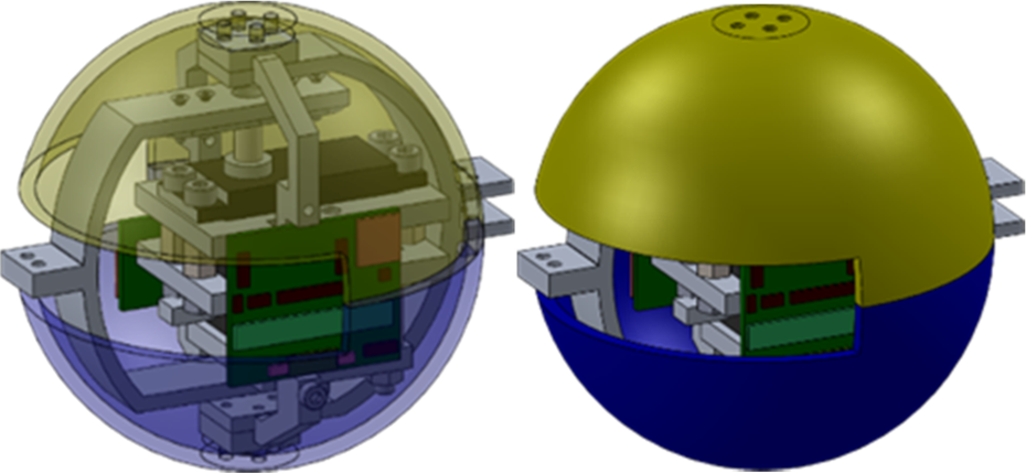
Link of snake robot.

Snake robot SnIPE.
The diameter of snake robot link is L = 102 mm and weight of link is w = 406 g. Assuming all 11 robot links and also camera on head link, the whole robot length is 1045 mm and the weight of robot is 4480 g.
Design of electronic parts
Individual links are connected together through the communication interface Serial Peripheral Interface (SPI). Each robot link is controlled by the microcontroller, ATmega8-16PU, Atmel, with a clock frequency 16 MHz. This microcontroller controls the positioning of servo motor concerning the required position based on the requirements of master robot link. So, all of other links are in slave position. Master microcontroller is in rear robot link and using SPI communication it communicates with the main control system—PC through universal asynchronous receiver/transmitter (UART). Slave microcontrollers also detect the actual position of servo motor by signal from servo motor potentiometer.
Each robot link has independently powered servo motor of 7.4 V and independently control unit of 5 V from power supply by cables connected to the rear link. All robot links also have a three-axis accelerometer MMA7361LC, Freescale Semiconductor for measuring the kinematic variables during an experimental analyses. The scheme of robot control systems is shown in Figure 3. The inside view of SnIPE can be seen in Figure 4.

Control system of snake robot SnIPE.

View to inside of snake robot link, inside of CoRL.
Design of locomotion pattern
For pipe inspection tasks, several kinds of mechanisms such as wheel-based or track-based robots can be applied, as was mentioned earlier. From the view of control, these robots are not difficult and therefore they are often used for inspections. Next kind of inspection mechanisms are bristled mechanisms that use friction difference between bristles and walls of the pipe. However, their load capacity is very low and thus they are not suitable for more complex applications. All the mentioned mechanisms are designed mainly for straight pipes, eventually for pipes whose diameter is high enough in order to possibly pass through the curved pipes (wheeled and tracked robots).
The use of snake robots is very suitable for these applications. Their kinematic configuration allows them adapt to the roughness of terrain and so they are appropriate for complex environment, where conventional mechanisms should fail.
The core of this research lies on applying the snake robot for inspection of provisional pipe with rectangular cross section. Robot should be able to pass through straight and curved pipe as well. Within this research, the type of locomotion, the so-called traveling wave (for straight pipe) is investigated. Using this type of locomotion, robot uses interaction of its body with walls of the pipe. By gradual undulated motion with the aid of continual contact with the walls of the pipe at minimum two points, robot will perform forward motion. The following figure shows the sequence of motion of snake robot moving by traveling wave.
Of course, there are also certain restrictions to this locomotion. For example, while passing through the pipe, there have to be some contact points of snake robot links and the walls of pipe. The robot has to have at least two contact points during its straight pipe locomotion.
According to Figure 5, with respect to the geometric aspects of Figure 6, the distance travelled can be expressed during one locomotion cycle:

Motion of snake robot by traveling wave.

Relation between snake robot and pipe.
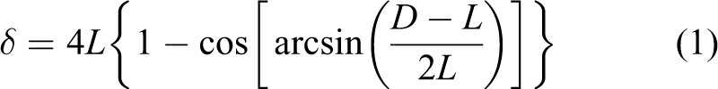
From equation (1), the distance travelled c δ is a function of pipe diameter D and diameter of robot link L

Equations (1) and (2) are correct when robot link has a spherical shape. The angle of curve, which robot describes by its body, depends on the pipe diameter D and diameter of robot link L

According to Figure 6, the curve of snake robot presents the discrete function of sin. On one hand, within this research, narrow pipe is considered for demonstration of motion in straight pipe and also wider pipe by, which will be demonstrated, passing through the curved pipe.
Robot passing through the curved pipe is shown in Figure 7. According to Figure 7, robot reached the end of the pipe (phase 1) and now it needs to continue so that it changes its direction about 90°. During phase 2,coordinates of the point need to be determined, where robot should move its head link. By this way, it can be ensured that links 1–5 will be fixed and robot can move other links 6–11 (phase 3). During phase 3, robot bends links 6–11 so that the rear link can be moved to the corner of the pipe. In the last phase, robot reaches the initial position as in phase 1 but with the direction turned about 90°.

Snake robot passing through the curved pipe.
To generate path for head and rear link during particular phases, can be snake robot in Figure 7 considered as manipulator. Manipulator has typically its base fixed to the ground, while its links are movable. The same view can be applied on the snake robot. It is important to ensure during all phases (curved pipe) that robot links form such fixed base and other links can move according to the requirements. Based on this idea, approach will be described for path generating and subsequently this generated path will be implemented in inverse kinematics solver. The methodology is demonstrated in the section “Experimental verification of designed control system with snake robot” of the article.
Mathematical background of control system
The aim of this section is introduction of basic principles for generating path for snake robot links by considering the walls of the pipe. The output of this solution is used as input to the inverse kinematic model with consideration of joint limit avoidance, obstacle avoidance, and singularity avoidance. Based on these aspects, a control system can be designed. For generating links’ path, potential field method is used. This approach will be demonstrated for motion in curved pipe.
Generating of path for head and rear link
In context of this research, path generation is understood as generating path for head and rear link with consideration of the sequence of motion according to Figure 7. Of course, the walls of pipe represent geometrical constraints which particular robot links have to avoid. Now the task is to model the walls of the pipe as a set of obstacles using the potential field method.
Potential field method
Path planning for the snake robot by potential field method is based on a simple idea. The main idea is to attract the navigated robot to goal position at the same time as navigated robot is repulsed out of obstacles. This method defines potential functions of goal position and obstacles position and generates the direction of motion. 11 In general, a potential field is a vector field obtained by applying a gradient operator as a function. The reference position of robot is evaluated using the higher value of potential as the goal value, which is also the global minimum of potential. The positions of obstacles are evaluated by higher potential as free space around the robot. So, the finding of suitable path for robot actually means finding of global minimum. Disadvantage of this method can be stopping robot in local minimum. 12
Potential fields can be divided into two fields, namely, attractive and repulsive field. Total field is expressed as the sum of both 13

where
Attractive potential function
An attractive potential function is a function of relative distance between head (rear) link and goal, to which the link tends. In general, attractive field can be described as 14
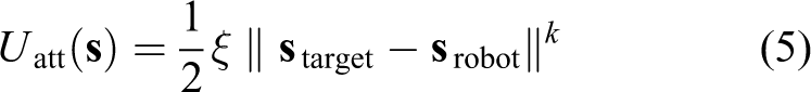
where ξ is the positive scaling factor,

An example of phase 2 is demonstrated in Figure 8. The head link has to move into goal position, which is indicated as dark blue. Dimensions in graph are in scale.
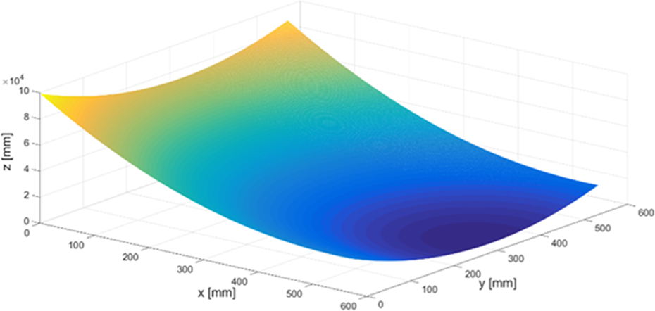
Attractive forces with focus on goal point.
Repulsive potential function
The role of repulsive potential field is to generate high potential in an area of obstacles so that gradient flow tends out of the obstacles. This ensures avoidance of collision between obstacle and robot. Repulsive function can be expressed by the following equation 14

where
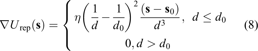
where
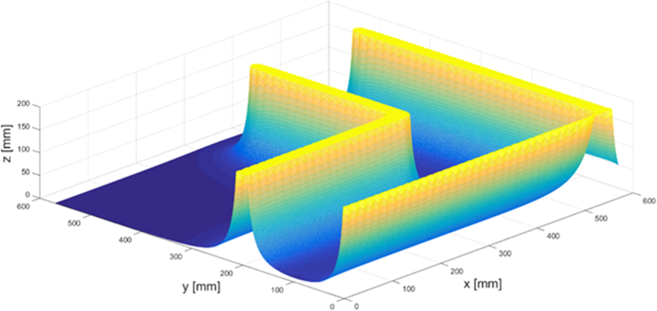
Repulsive forces shaping the pipe.
Graph is shown in a scale again. As can be seen from Figure 9, by suitable positioning of particular circles, it is able to generate repulsive forces that shape continuous objects. Set of obstacles shaping the pipe can be defined as
The resultant potential field can be obtained by addition of attractive and repulsive field. Subsequently, field vector
The curved pipe and initial position of head link (brown color) at the beginning of phase 2 are shown in Figure 10. The goal position into which the head link has to be moved is also shown (red color). It can be seen that the positions of obstacles act as repulsive forces. The path of head link during phase 2 is indicated as green. By analogy path can be generated for head or rear link, for particular phases of locomotion. While head link has to follow the generated path, other links have to keep such generalized variables
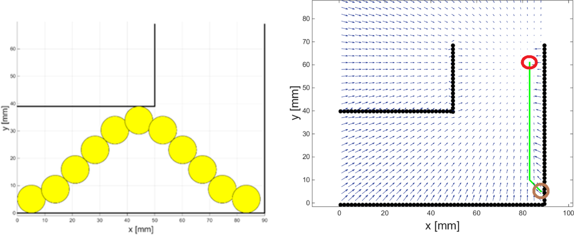
Resultant potential field.
Inverse kinematics task
The task of inverse kinematics is computing and time-consuming considerably more exacting task as task of direct kinematics. This is true mainly in the cases like snake robots, which can be considered as redundant or hyper-redundant mechanisms, difficult from the view of control. The problem of inverse kinematics can be defined as calculation of corresponding variables (position, velocity, and acceleration) from work space to the joint space.
Let’s have a task space trajectory

for

where

provided that n > m (n = 11, m = 2).
The task of inverse kinematics is to position particular snake robot links to required positions. Within this research, we also assume that robot moves in environment with the obstacles (walls of pipe) and therefore there is necessary to include the obstacles avoidance task into the inverse kinematics solver. Moreover, based on the section “Design of snake robot SnIPE,” snake robot SnIPE has restriction in the form of joint limitation ±45°. This fact has to be also included into inverse kinematics solver as joint limit avoidance task.
The inverse kinematics task can be divided into several tasks. In our study, the main task is positioning of head or rear link into required position during motion in curved pipe. The additional tasks are joint limit avoidance as well as obstacle avoidance. The last task is singularity avoidance.
Joint limit avoidance task
Joint limit avoidance task is performed only at certain time. In other words, this task is activated or deactivated based on whether particular robot link is in the area of its geometrical limitation. This additional task is activated or deactivated by suitable choice of weight matrix

Ww
is the constant weight. This value is usually higher than the value chosen for main task and singularity avoidance task. Next, it is necessary to define Jacobian

where
Obstacle avoidance task
In obstacle avoidance task, the solver periodically evaluates the presence of obstacle in the area of moving robot link. In our case, solver will periodically evaluate the distance between particular robot links and walls of the pipe (defined in previous section). Links of robot will be modeled as segment from the joint i at the Cartesian coordinates xi to the joint i + 1 at the Cartesian coordinates xi + 1. Unit vector determining direction of link with length li is expressed as 16

Considering Figure 11, to each obstacle (also obstacle with unsymmetrical shape) the so-called obstacle active area (OAA) or influence of obstacle can be assigned, which is circular shape with radius r
0. Let the center of the assuming obstacle has the coordinates
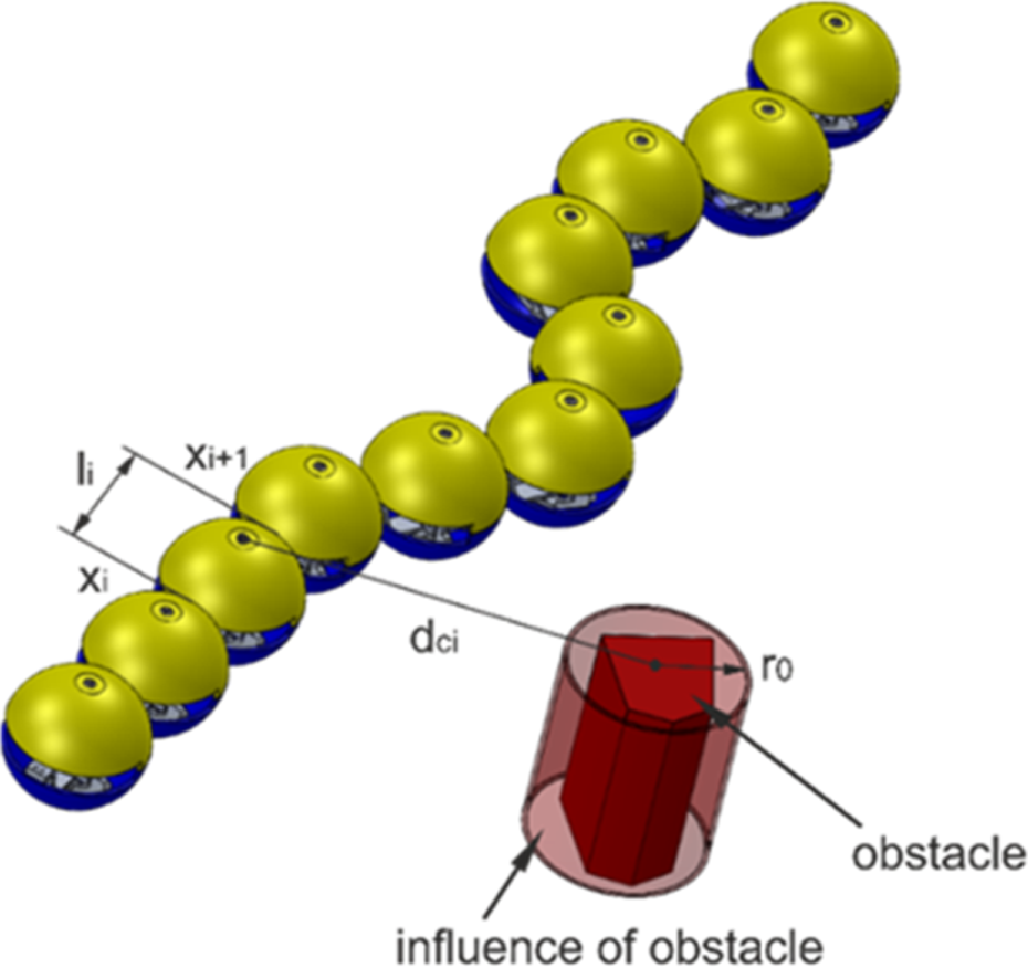
Snake robot with obstacle.

Subsequently, the coordinates of potential point of robot collision with obstacle can be expressed as

The coordinates of potential point of robot collision are used for expression of mutual distance between this point and center of OAA

Next important issue within modeling of obstacle avoidance task is to determine Jacobian

where

Jacobian

Jacobian
Solution of inverse kinematics
The basic idea of inverse kinematics solution in our case is to minimize the cost function. The main task is defined as

where
Cost function can be solved as

By substitution of equation (21) into equation (22), one obtains

Now, equation (23) includes one main task that has to ensure precise positioning of robot links, two additional tasks consisting of joint limit avoidance as well as obstacle avoidance. The last task is singularity avoidance. Let’s consider
Experimental verification of designed control system with snake robot
Designed methodology of control system can now be demonstrated with snake robot SnIPE. Snake robot SnIPE was tested within experiments with designed methodology using straight as well as curved (shape L) provisional pipe built from modular profiles. The aim of the experiments was not to measure precise path following robot links but test methodology with mentioned locomotion modes using approaches mentioned earlier.
Control system
The algorithm of control system was implemented using software Matlab. Although having a remote control of snake robot would be a more convenient solution 17 because of closed environment (pipe), the robot works on cables. The inputs into control system are basic parameters given by user, parameters such as diameter of pipe (constant along the pipe), diameter of robot link, and type of pipe (straight and curved). The scheme of the control system is shown in Figure 12.

Control system.
Considering straightforward locomotion, the output of Matlab script involves a sequence of joint angles
Snake robot is equipped by the sensor of obstacles, Sharp GP2Y0A41SK0F, ©SHARP Corporation, and also by stereo camera DUO3D, DUO3D™ Division. Through the PC, the user can watch information from sensor as well as record from camera. The stereo camera will serve in navigation tasks in the future.
Control algorithms
Particular algorithms used for this experimental study differ from each other, that is, according to how the robot moves through straight or curved pipe. Straightforward motion of snake robot uses the following algorithm:
Definition of basic parameters Determination of snake robot curvature and required angles for particular phases →
send read sensors data
Parameter phase depends on the curvature that the snake robot describes during its motion and also on the number of snake robot links of which robot consists of. Angles vector
More difficult algorithm is used in the case of curved pipe. Now, navigation method and also inverse kinematics have to be implemented into control algorithm.
Definition of basic parameters Determination of goal points for head and rear links
Compute joint limits, relations for obstacle avoidance, Jacobians send read sensors data
In equation (23), matrix
Algorithm for master microcontroller lies on reading the information through USART from Matlab and then sending these information about required the position of particular links to slave microcontrollers. Slave microcontrollers constantly read information from master microcontroller and also control servo motors.
Motion in straight pipe
Testing of snake robot SnIPE was performed in provisional pipe built from modular profiles. The pipe width is D = 170 mm and diameter of robot link is L = 102 mm. Straightforward motion of snake robot was applied using locomotion according to Figure 5, which consists of six phases. During testing, control algorithm works with infinite loop. The distance traveled by snake robot can be seen in Figure 13.
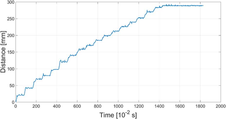
Traveled distance in straight pipe.
The course of traveled distance changes quasi by steps, which is caused by fall time of snake robot wave from rear link to head link (see Figure 5). Each robot link includes three-axis accelerometer for purposes of determination of kinematic variables during experiments.
The record of robot motion in straight pipe is shown in Figure 14. Every 2 s, a sequence of images are obtained. It is important to say that robot moves on plastic smooth surface. When the surface would be replaced by rougher surface, which means higher coefficient of friction, this kind of locomotion should be slower and in the case of too high friction coefficient almost impossible. Nevertheless, more detailed analysis of this theme is out of range of this article.

Locomotion of snake robot in straight pipe.
Head link of snake robot SnIPE includes stereo camera DUO3D MLX, DUO3D™ Division with built-in Infrared (IR) filters, whereby it can monitor the pipe. Shots from stereo camera are shown in Figure 15.
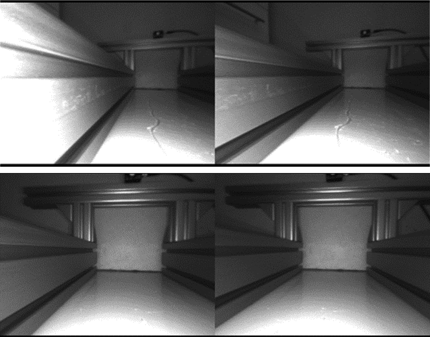
Shots from stereo camera during locomotion.
DUO3D offers output in several forms. During our application, camera was used only for video recording.
Motion in curved pipe
During next experiment, algorithm 2 was tested and designed, which serves for passing through the curved pipe (shape L). The provisional pipe was built from modular profiles again. Diameter of the pipe is D = 390 mm. Input parameters like diameter of the pipe, required points for path generation

Locomotion of snake robot in curved pipe.
The experiment started by phase 2, when robot reaches the end of the pipe (phase 1 in Figure 7). In time 0–12 s, the robot used its rear links for fixation purposes, while the head link with other fore links can move to the required position of head link. After 12 s, robot starts fixing its body by fore links and its rear links move in to position parallel with the wall of pipe. Subsequently, rear link moved into pipe corner. From 28 s robot started push from pipe corner and snake robot body obtains shape that it had at the beginning of the phase 2 (Figure 7) but turned about 90°. From this moment, robot can continue with its locomotion by algorithm 1.
Conclusion and future work
The article shows application of snake robot for inspection purposes in straight and curved provisional pipe. At first, the snake robot SnIPE is introduced, which was developed for experimental analysis of pipe inspection tasks. In this article, the way of locomotion through straight and curved pipe is established. For these purposes, there was shown potential field method with modeling of the walls of pipe as robot obstacles. Output of this method (generated robot path) is subsequently used by solver of inverse kinematics. Inverse kinematics in this research includes obstacle avoidance task, joint limit avoidance task, as well singularity avoidance task. Introduced model was demonstrated on snake robot moving in the pipe. The goal of the work was verification and testing of designed methodology. According to the results obtained, designed methodology can be used for snake robot motion in pipe. The main contribution of this article is new methodology for overcoming elbow of pipe by snake robot using potential field method with cooperation of inverse kinematic model.
Within this research, robot works in cooperation with user by defining the required positions in the pipe, which were used for generating path for head and rear links. In the future, our research team would like to extend this application to be autonomous which means that robot based on its sensors equipment should consider geometric aspects between robot and pipe and be able to compute required points for path following. Robot would be fully autonomous during its locomotion and inspection of the pipe.
Footnotes
Declaration of conflicting interests
The author(s) declared no potential conflicts of interest with respect to the research, authorship, and/or publication of this article.
Funding
The author(s) disclosed receipt of the following financial support for the research, authorship, and/or publication of this article: A contribution to the research of measuring strategy in coordinate measuring machines. This contribution is also the result of the project implementation: Centre for research of control of technical, environmental and human risks for permanent development of production and products in mechanical engineering (ITMS: 26220120060) supported by the Research & Development Operational Programme funded by the ERDF. This article is also contribution is also result of grant project VEGA 1/0872/16 and VEGA 1/0751/16.