
Abstract
The cable-based parallel camera robots possess characteristics of solitary way force, redundant actuation, and high-speed mobility. Therefore, research and solution on the stability are a challenging problem. In the available research literatures, there are limited studies to analyze the factors on the system stability for the high-speed cable-based parallel robots. However, when long-span cables and high maneuverability are involved, the effects of cable inertia on the dynamics should be carefully taken up. Thus, in this study, the effects of cable inertia on the stability of the high-speed cable-based parallel camera robots are studied. The dynamic model of the cable-based parallel robot is deduced with cable inertia based on the time-varying cable length dynamic model, the end-effector dynamic model, and the drive system dynamic model. Then, a tracking-control strategy for the camera robot is proposed based on a modified proportion-derivative (PD) forward controller in the end-effector position space. Further, the control strategy is demonstrated based on Lyapunov stability theory. Finally, numerical results show that camera robot is of stable-tracking performance. The control strategy is an effective approach to improve the stability of the camera robot.
Keywords
Introduction
Cable-based parallel robots have been defined using actuated cables to operate the end-effector. Cable-based parallel robots have attracted significant attention lately due to their outstanding advantages over the rigid-link parallel robots, such as simple structure, high payload, high speed, stable gantry configurations, small inertia, removable reorganization, and large workspace. 1 The cable-based parallel robots satisfy different functional and performance requirements in a variety of practical applications. They are studied from different fields (e.g. statics, 2 dynamics, 3 kinematics, 4 institutional performance analysis, 5 and control theory 6 ). They are defined a range of different performance evaluation indexes from distinct perspectives (e.g. workspace, 7 singularity, 8 stiffness-extreme value, 9 cable-tension optimization, 10 and accuracy error 11 ). It is proposed that the theoretical analysis and calculation methods guide the development research and applications for the cable-based parallel robots. Since the unidirectional force cable is easy to cause instability, cable-based parallel robots are facing more challenges in high-speed motion. The stability plays a major role in the high-speed motion of the cable-based parallel robots. Therefore, the stability analysis is required for the cable-based parallel robots.
As shown in Figure 1, this is a 5 m model for a cable-based parallel camera robot in our laboratory at present. Speed control mode is adopted in this model. However, because of the limited workspace of the model, it is only suitable to validate the principle of the control mode, which cannot be used for high-speed experiments. There are a few famous commercial cable-based parallel camera robots, such as SpiderCam 12,13 and SkyCam. 14,15 However, little theoretical researches have been concentrated on camera robots. Thus, it is required for us to deal with systematic theory researches on camera robots. The camera robots take two illustrious motion characteristics. One is high speed and the other is abnormal demand for stability. If the camera robot is instable, image will be blurred and it cannot satisfy the demand of tracking shot. Hence, analyzing the factors on the stability of camera robot is of great importance to improve its stability.

Five meter model for a camera robot.
Several studies have been already conducted on the stability for the cable-based parallel robots in the past. Bosscher and Ebert-uphoff 16 proposed a method to measure the stability. The measure was designed to explain how much the mechanism was affected under the unknown external forces. However, this measure was only for the unconstrained parallel robots. Behzadipour 17 and Khajepour 18 established the stiffness model in which a cable was equal to four combination springs. They discussed the stable relationship between the stiffness matrix and mechanisms and suggested the necessary and sufficient conditions for stiffness matrix positive definite and system stability. However, since different springs were with different stiffness matrixes, the stiffness model that a cable was equal to four combination springs under no pretension was imprecise. Thus, it is needed to discuss the degree of approximation. Korayem and Bamdad 19 established the stiffness model considering cable sag and flexibility and analyzed the stability based on the characterization of the stiffness matrix of the cable-suspended manipulator. Jiang and Kumar 20,21 put forward an approach for the stability analysis based on the Hessian matrix for three-dimensional cable systems with multiple aerial robots. They pointed out that when the Hessian matrix was positive, the corresponding equilibrium configuration can be regarded as stable. Carricato and Merlet 22 proposed an optimization algorithm to analyze the stability for the unconstrained cable-based parallel robots. However, this study was limited to the unconstrained cable-based parallel robots in static balance. Liu et al. 23 discussed the minimum cable tension distributions for the completely restrained cable-based parallel robots. The results showed the minimum cable tension distributions in the workspace by three performance factors and illustrated the relationship between the three performance factors and the stability. However, in the earlier studies, they only analyzed the structural stability without considering the motion stability.
Kawamura et al. 24 developed a PD controller accompanied with gravity compensation and internal forces in the wire length coordinates. Stability of motion was analyzed using the Lyapunov theory and the vector closure condition. Alp and Agrawal 25 designed a feedback controller built on Lyapunov stability theory to assure positive cable tensions for cable-based parallel robots. Kino et al. 26 studied a robust PD control for the wire-driven parallel system by the uncertain Jacobian matrix. They proved the motion convergence to desired positions and described its robustness based on Lyapunov theory. However, the control method was used only under zero-gravity conditions. Oh and Agrawal 27 proposed a feedback control law for cable-suspended robots under input constraints based on control Lyapunov functions. Nonetheless, the technology is only applicable to the planar parallel robots. Vafaei et al. 28 presented an approach to the control of the KNTU CDRPM using an integrated control scheme. It described the asymptotic stability of the closeed-loop system in detail. However, the method was just for the redundant constraint cable-based parallel robots. Khosravi and Taghirad 29 and Babaghasabha 30 presented a robust proportion integral derivative (PID) controller for the fully constrained planar cable-driven parallel manipulators. The stability of the closed-loop system was discussed using Lyapunov second method and it was found that though selecting the suitable controller gains, the closed-loop system would be stable. However, there is no discussion on whether the algorithm is applicable to the high-speed motion. The above literatures put forward some control strategies for the cable-based parallel robots, and the stability of the control algorithm is demonstrated based on Lyapunov stability theory. However, the effect of the cable-based parallel robots on high-speed motion has not been clearly described. Moreover, these control algorithms are not appropriate for high speed and high-maneuverability motion.
As shown in the above literature surveys, the stability of cable-based parallel robots has been observed, while, only a limited number of articles deal with the stability of the high-speed cable-based parallel robots with cable inertia. Therefore, the objective of this work is to study the stability problem for the high-speed cable-based parallel camera robots and explores the factors on stability.
The structure of this article is organized as follows. First, the dynamic model of the cable-based parallel robot is established with cable inertia in the section “System dynamic analysis.” Then, a modified-PD feed forward control law designed along with stability analysis is introduced in the section “Trajectory tracking control strategy.” In the following section, the detailed performance analysis along with numerical simulation is described and discussed extensively. Finally, the section “Conclusions” summarizes the conclusions of this research.
System dynamic analysis
Catenary model
The camera robots are a special class of the cable-based parallel robots, whose end-effectors are actuated by cables, as shown in Figure 2. It consists of a moving camera platform with three translational degrees of freedom connected to the fixed pulleys by a set of four cables. Each pulley is attached to the ceiling of a mast. The camera platform moves freely in every direction because the cables can be deployed and retracted by four servo motors mounted to the fixed base.

General model of a cable-based parallel camera robot.
The effects of the cable sags on the dynamics must be taken into account for large-span cables.
31,32
Therefore, a cable catenary model is first established. The local coordinate system

Schematic diagram of a catenary model in the vertical plane.
q is the uniform load along the cable length under its own gravity, which is found to be

where
According to the arc length formula, one obtains

Substituting equation (2) into equation (1), the relation is expressed as

Upon rearranging equation (3), the solution to the boundary conditions shown in Figure 3 is obtained. 33 It is given as

where
Equation (4) stands for a catenary in mathematics, which describes the shape of a cable under the action of gravity. Given the coordinates of any point on the curve, the entire curve can be completely determined.
According to the formula derivation, the cable length is given by

When

Cable dynamic model with time-varying length
As shown in Figure 4, the global coordinate system

The space discretization of catenary element.
As shown in Figure 5, the motion of pij is composed of the out-of-plane motion and the retractable axial motion. Due to the high maneuverability of the cable-based robot, the cable lengths change rapidly. Hence, the axial velocity and acceleration cannot be ignored for the cable, leading to no negligible inertia. As a result, the dynamics model for a node pij is given by
34
Motion decomposition diagram of node pij on cable.

The speed and acceleration of the note pij can be obtained by solving the first-order and the second-order derivative of

where
The first-order and second-order partial derivative of

The span ratio of the cable-based parallel robot is so small that

where
Assuming

Consider

In which
End-effector dynamics model
The decomposition diagram of the cable tension Ti at the end node Bi is shown in Figure 6.

Decomposition diagram of cable tension.
Because the cables are under tension, the camera robot should be driven redundantly in order to make the end-effector be completely controllable. If the motion trajectory of the end-effector is known, then there is more than one solution for the kinematic equation. However, it is necessary to count each cable tension in real-time in the actual motion control. Therefore, optimizing the cable tensions to obtain a unique solution is necessary. 10 In this article, the minimum variance of cable tensions is the optimization goal, which uniquely determines the cable tensions solutions. 36
It is assumed that the robot is tensional, meaning that the cable tensions can be generated in all cables at the same time. A moving reference frame, noted by
Hence, the dynamics of the end-effector in the global coordinate can be written as follows

where me is the mass of the end-effector,
On simplifying, equation (13) becomes as follows
where
Actuator dynamics model
The actuator of a cable-based parallel robot includes motors, speed gears, and winches. The actuator dynamics can be formulated as follows 37

where
System dynamic model
When the motor rotation is ϕ, the cable length will cause a variation ΔL. Hence, the relationship between cable length and motor rotation is expressed as follows

After differentiating, the above equation can be rewritten as follows

Since

Upon rearranging the above equation, the following equation is obtained

In which

Trajectory tracking control strategy
PD-modified feed forward control
The cable-based parallel robot is a highly coupled nonlinear system. More importantly, it is a redundant drive system. Hence, it is necessary to decouple for the dynamic model before the control scheme is designed.
In order to modify the vibration errors caused by cable inertia after starting, a modified-PD feed forward control law is put forward in this article, as shown in Figure 7. The cable vibration can lead to tracking error and adverse effect for the work quality of the camera robot. So, it is necessary to design a controller for reducing the cable length errors as much as possible in the normal track shooting process.

Diagram of control strategy.
Assuming a desired position, the modified-PD feed forward control law is given as follows

where

It is worth noting that
By substituting equation (21) into equation (19) and using equation (22), the closed-loop system is expressed by

Stability analysis
The stability of the control strategy for the cable-based parallel camera robot is described in this section.
The Lyapunov stability theory is the most common method for the stability analysis of mechanical systems. The stability of the system can be defined without solving the state equations through this method. It is very convenient because solving nonlinear equations is usually quite difficult. The main thought behind the Lyapunov stability theory is that supposing the energy of a mechanical system is always being consumed, and then the system must eventually converge to an equilibrium position. 38
First, Lyapunov function candidate V is established for the closed-loop system (23). According to the energy of system, the candidate Lyapunov equation is given by 39

The time derivative of the Lyapunov function V can be written as

Upon substitution of equation (23) into equation (25), one obtains
According to the dynamic equation of the robot, the robot system has the following structural characteristics.
40
Matrix

Thus, equation (25) can be simplified as

Since

Uniform continuity
From equation (29), we know that
The equation shows that
Numerical simulation
Description of the camera robot
In order to prove the effectiveness and stability of the control strategy, a simulation study is carried out. One particular type of three-degree-of-freedom cable-based parallel camera robot that uses four cables to maneuver the work platform is used for simulation and analysis. It should be noted that the camera robot is a fully constrained redundant drive system.
The ground field center is considered as the origin of the global coordinate system. The geometric and mechanical properties of the camera robot for the simulation are listed in Table 1. All the cables have the same parameters. The simulation time is
Simulation parameters for the camera robot.

The end-effector is demanded to track the following space circular helix trajectory

The initial pose of the end-effector for the camera robot is
Results and discussions
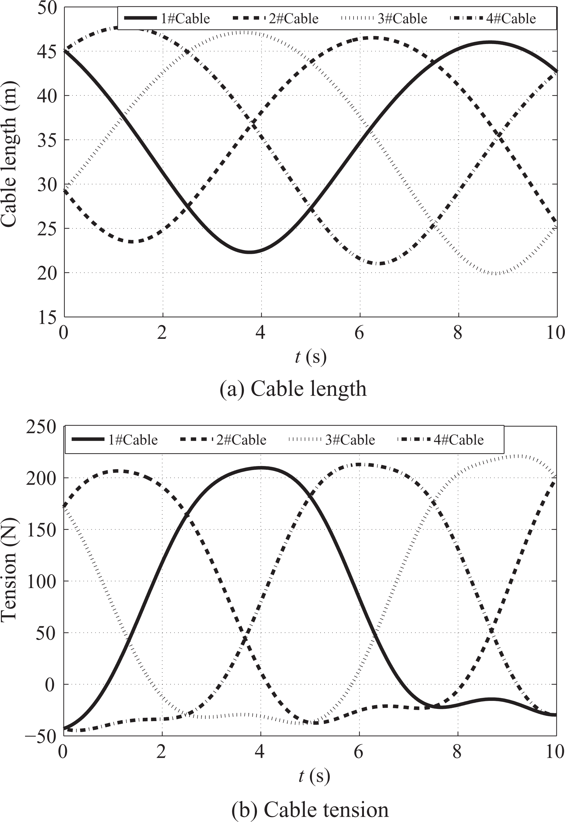
The cable features under

Cable features under v = 6.31 m/s.
The cable features under
Cable features under v = 9.44 m/s.
The tracking performance under different speeds of the cable-based parallel camera robot using the modified-PD feed forward controller is illustrated in Figure 10. It can be seen that in the first 2 s, the end-effector is in the starting state and the errors are relatively large. The ideal models have been assumed in the simulation. That is to say, there is no perturbation in the system model. It is assumed that there is no uncertain interference. Hence, starting errors are mainly caused by the longitudinal vibrations of the cables. For the large-span system, the mass of the cable cannot be ignored. So, the vibration caused by the cable inertia in the starting state leads to the starting errors. The cause of the severe vibration at a high speed is that the sudden start-up of the end-effector requires greater cable tensions. It is clear that the larger the cable tensions are, the higher natural frequencies of the transversal vibration of the cables will be. 42 The longitudinal vibrations of the cable are increased. Of course, the cable sag has a great effect on the natural frequencies and will cause relatively great vibrations. It is necessary to choose suitable cables. The starting error elimination problem will be solved in the future research. However, whether the position error or the speed error, it is convergent to a very small range in the normal operation state. That is to say, the PD-modified feed forward controller can effectively mitigate the cable vibration. So it can be said that the results are satisfactory and the PD-modified feed forward controller achieves the desired stable state values with minor errors.

Errors under different speeds.
Figure 10 shows the position tracking errors of the simulationand the speed errors. In order to analyze the tracking performance with PD-modified feed forward controller under different speeds, four varying speed conditions have been taken, namely super high-speed motion with
It can be noted in Figure 10 that there is a slight beating of the end-effector within the first 2 s because of the cable longitudinal vibration. But the position tracking errors for the stable state immediately converge to small values. At this time, the motion of the camera robot is in a stable state. Furthermore, as shown in Figure 10, it is observed that the greater the motion speed, the greater the position tracking error will be. Namely, cable longitudinal vibration is more serious at high speed.
As shown in Figure 10, it should be noted here that the speed response time for the PD-modified feed forward controller is within 2 s at low speed. The motion speed converges at the desired trajectory 2 s later, and the camera robot runs stable. The speed response time is up to 4 s due to the increase in cable vibration when the end-effector is at a high-speed motion. Then, the speed tracking errors are gradually convergent. From these figures, it is clearly observed that the tracking errors are convergent and the motions are stable, which satisfies the requirements of the trajectory tracking control for the camera robot.
In order to compare the position-tracking performance of the PD-modified feed forward control with PD control and traditional PID control; the position tracking errors under high-speed motion are shown in Figure 11. As seen in this figure, the PD-modified feed forward control strategy can effectively improve the position tracking error norms. This effective improvement is due to the fact that the cable length errors play an important role in the system stability, while the cable length feedbacks ensure better tracking of the camera robot. It can be calculated that the real-time cable length feedback correction is effective and reasonable to improve the tracking stability for camera robots.

Position tracking errors under different speeds.
The simulation results for the relationship between the motion speeds of the end-effector and the absolute values of the maximum position tracking errors in the normal operation state are shown in Figure 12. They used the modified-PD feed forward control law. It is quite noticeable that the Z-directional motion error increases exponentially with increasing speeds, which illustrates the cable vibration caused by inertia increases with increasing motion speeds. It is then well-known that the cable vibration leads to increase inposition track errors, which lead to the end-effector unstable. It is also worth to discuss that the Z-directional motion errors are larger compared with the X-directional and that of the Y-directional because of the vibration is mainly determined by the inertia of the cables. The vibration in the XOY plane is very small. It can almost be neglected. 41 So, it is very necessary to design a controller to suppress the cable vibration, which is the aim of this article.

Some features under different speeds.
Meanwhile, the relationships between the motion speed of the end-effector and the minimum cable tensions are described in detail in Figure 12. It is noted that the minimum cable tensions decrease with increasing speed. Because the greater speed causes the greater acceleration, and the greater resultant force will be. While gravity is constant, the minimum cable tensions decrease. It is interesting to note that when the operating speed is
Figure 13 shows the cable length feedbacks of the camera robot in the case of high-speed motion and slow motion. As it is seen in this figure, the cable length feedback under high speed is nearly 10 times larger than the low speed one. It shows that the position track errors under high speed are larger. That is to say, the cable vibration is more intense in high-speed operation. It is worth noting that in the first 2 s, the end-effector is in the starting state, the error is relatively large because of the inertia. So the cable length feedbacks are large. However, it is convergent to a very small range in the normal operation state. That is to say, the PD-modified feed forward controller can effectively suppress the cable vibration. Furthermore, it takes 2 s to adjust the cable length errors for the control system when the end-effector is in low-speed motion. After adjustment, the change of the cable length is smooth. The end-effector is in stable operation state. It is worth noting that the cable length feedbacks of each cable are different, that is, cable length errors of each cable are not the same. The more the cable vibration, the more the cable length feedbacks will be.

Cable length feedbacks under different speeds.
The values of the dynamic model parameters affect the position tracking errors, which are depicted in Figure 14.
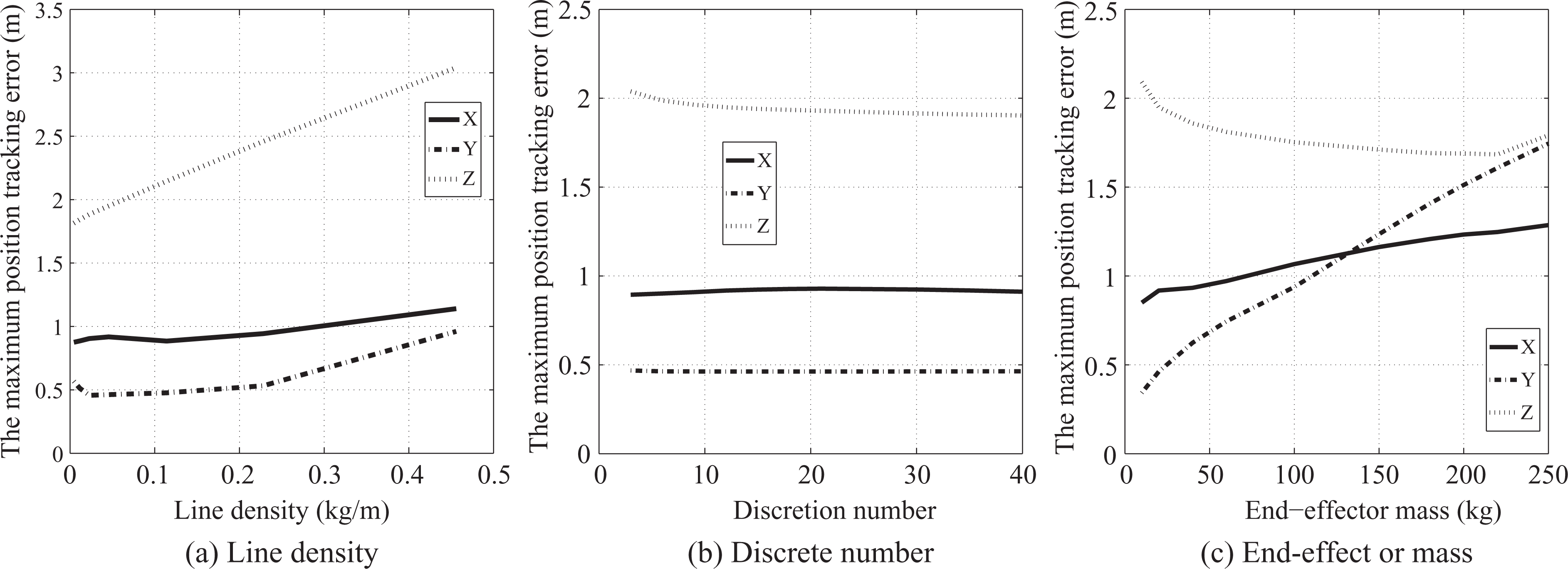
Position tracking errors under different parameters.
By increasing the cable line density, the position tracking errors can be raised as shown in Figure 14. It can be noted that the position tracking errors increase with increasing cable line density. It is indicated that the cable inertia plays an important part on the position-tracking performances. The results indicate that the greater the cable mass is, the severer the cable vibration is, and the worse the stability of the camera robot system is. Consequently, the stability of the camera robot system is greatly affected by the selection of the appropriate cable. Moreover, position tracking errors in the Z-directional are larger than that in other directions. That is to say, the influence of cable line density on Z direction is greater.
The influence of different cable discretion numbers on the position tracking errors is shown in Figure 14. It should be noted here that the cable discrete number doesn’t appear to have influenced the position tracking errors of the end-effector too much. Moreover, it is noted that even if the discretion number increases, the position track errors are hardly changed. As a consequence, given the time cost, it is necessary to choose a small and reasonable discretion number.
In addition to this tracking simulation, the PD-modified feed forward controller is verified using payload variations as shown in Figure 14. It can be seen that the position track errors are not the same in different directions, the Z-directional motion error is far greater than the other direction. Because the cable inertia causes more obvious vibration. It is observed that with increase in the load, the variations in the position tracking error increase for the X-directional and Y-directional, while the Z-directional is the opposite. The variations of the X-directional motion error and that of the Y-directional are linear increasing, while the variations of the Z-directional are decreasing. With increase in the end-effector load, the inertia increases for the X-directional and Y-directional. That leads to larger vibrations in the horizontal plane. So the maximum position tracking errors increase. On the contrary, the cable tensions are larger for the Z-directional with increase in the load, the smaller vibration in superior inferior direction. Hence, the tracking accuracy is higher and the tracking error is small. Therefore, the mass of the end-effector should be optimized reasonably and effectively.
Conclusions
The dynamics model, control strategy, and stability of the high-speed cable-based parallel robots with cable inertia are studied in detail in this work. Based on the results, the following conclusions can be made: The dynamic model of the time-varying cable length is established based on the finite element method. The dynamic model is established using Newton Euler equation for the end-effector. Further, the dynamic model of the drive system is also established. On this basis, the dynamic model of the cable-based parallel robot is deduced with cable inertia. A tracking control strategy for camera robots is proposed based on a modified-PD feed forward controller in the end-effector position space. Its stability has been proven with the Lyapunov stability theory, and its uniform continuity has been proven using Barbalat’s lemma. The performance of the tracking controller is examined through simulation studies with three-degree-of-freedom cable-based parallel camera robot with four cables. By the simulation results, it has been shown that the dynamic model is effective, and the control strategy is stable. The position tracking error and speed error can be quickly convergent, reaching a relatively high accuracy tracking results. The results presented here show that the high-speed cable-based parallel robots can achieve trajectory tracking stably and smoothly. The results showed that the end-effector mass, the motion speed, the cable line density, and the cable discretion numbers have significant impacts on the stability.
Footnotes
Declaration of conflicting interests
The author(s) declared no potential conflicts of interest with respect to the research, authorship, and/or publication of this article.
Funding
The author(s) disclosed receipt of the following financial support for the research, authorship, and/or publication of this article: The authors gratefully acknowledge the financial support of National Natural Science Foundation of China under Grants nos. 51175397.