
Abstract
The characteristic features of underactuated finger are compact structure, large grasping force, and simple operation. It has a wide application prospect in the fields of industrial robot, humanoid robot, human artificial limb, and space robot. A new type of fully rotating joint linkage-based underactuated mechanism is proposed, and a new method based on the law of minimum resistance is presented to realize the equivalent mechanism at different contact conditions of the finger and the kinematical analysis based on the equivalent mechanism. The kinematic equations and the limit moving position of the mechanism are derived using the proposed method. Finally, the numerical simulation is carried out by MATLAB program. The correctness and effectiveness of the proposed method are verified. The simulation results show that the proposed mechanism has a large grasp space and can achieve good grasp trajectory.
Introduction
In robot hand design, there are various differences in performance indicators such as volume, weight, and flexibility. In order to reduce the size and weight of the robot hand, it is generally handled through changing structure or material. High-strength aluminum alloy is usually used in the manufacture of robot hand. Carbon fiber-reinforced polymers have been researched and also used for manufacture. It has characteristics of high resistance to tension, good antivibration, and low density; however, the price is very expensive and the technology is not mature. Therefore, a more effective way is to optimize the structure of the robot hand by changing transmission mode and reducing the number of drivers. Underactuated finger mechanism has the feature that the number of drivers is less than the joint degrees of freedom. In this article, the underactuated finger mechanism is adopted. This mechanism can make robot hand grasp objects with different shapes and sizes. Thus, underactuated finger mechanism becomes an important research direction in dexterous robotic hands field. Changing transmission mode will be introduced in the following. 1
Underactuated robot finger generally uses tendon driven, friction wheel, or linkage mechanism with elastic element. The design of tendon finger mechanisms was first proposed by Mullen in patent in 1972. 2 Since then lots of research have also used tendon-driven mechanism. Sabetian et al. 3 proposed a compound robotic hand, which consisted of two underactuated tendon-driven fingers and a single-section continuous finger. Niola et al. 4 proposed an underactuated tendon-driven mechanical hand of five fingers. Andrianesis et al. 5 developed a multifunctional prosthetic hand with shape-memory alloy actuators, which used tendon-driven underactuated mechanism to provide the necessary dexterity. Ma et al. 6 presented a minimalist, four-finger hand comprising two pairs of tendon driven. As the tendon rope can bear limited pull, when the friction of the joints increased, the elastic deformation of the tendon will bring bad influence on the performance of the finger; thus, the tendon-driven underactuated mechanism could only be applied to some specific applications where the work load and finger contact force are small. 7
In order to realize underactuated finger which has compact structure and large holding force, the underactuated linkage mechanism must be adopted in design and manufacture. In the study of underactuated linkage finger mechanism, Gosselin 8 proposed a patent in 1998. The thumb of TH-1 9 hand and TH-2 10 hand of Tsinghua University proposed by Zhang et al. also used linkage mechanism, but the translational stroke is very limited, and the finger grasping force is small. Besides that, Begoc et al. 11 reported a pneumatical underactuated hand that can realize adaptive grasping of different objects. However, pneumatic system has big volume and weight and complex control. Shin et al. 12 proposed a humanoid robot hand, each finger has four links and three joints, and joints 2 and 3 are coupled by the four-bar linkage mechanism. Kim et al. 13 suggested a design of a novel gripper using a spherical five-bar linkage mechanism. In addition, Wu et al. proposed an underactuated linkage finger mechanism, 14 which has compact structure, and it can realize large grasping force. Since the mechanism contains a sliding joint with spring, the phalanxes need embed in its body a slider, a guide rail and a spring to form the sliding joint. These tiny elements make the phalanx is inconvenient to product and maintain. In order to overcome this problem, it is better to adopt fully rotational joint underactuated linkage finger mechanism. Zottola and Ceccarelli 15 reported a kind of fully rotational joint underactuated linkage finger mechanism. However, phalanxes 2 and 3 of the mechanism proposed by Zottola and Ceccarelli 15 are separated, that is, there are some unfixed space between phalanxes 2 and 3. Therefore, in some states, for example, when phalanxes 1 and 2 reach the object and are fixed, the distance between phalanxes 2 and 3 will be changed as the grasping move of phalanx 3, as shown in Figure 4 of the literature 15 . A new fully rotational joint underactuated linkage finger mechanism is proposed in this article to overcome these disadvantages.
In the design and analysis of underactuated finger mechanism, Seyoung 16 presented the development of a self-adaptive hand for performing dexterous manipulation tasks with the differential driving module. Alireza proposed a new approach to flexible multijoint robot finger mechanism, which consists of three links and is similar to a human finger. 17 Mishima et al. 18 designed a new underactuated robotic finger using a special transmission mechanism. The transmission mechanism consists of a set of gears and a spring to produce connected motions and adaptive curling. Petkovi et al. 19 analyzed a kinetostatic model of the underactuated finger mechanism. The underactuation is achieved by adding the compliance in every finger joint and uses adaptive neuro-fuzzy inference system as the soft computing method to perform the prediction of the finger contact forces. Wu et al. 20,21 finished modeling and kinematic analysis of static underactuated linkage mechanism simulated by MATLAB and completed the mechanical design and dynamic simulation of different adaptive mechanism grasping. Overall, the design of the underactuated linkage finger mechanism is still based on intuition, bionic, or simulation adjustment. 22 There is no complete theory of kinematic analysis of such complex underactuated linkage finger mechanism so far.
In the discipline of the underactuated mechanism movement, the research mainly focuses on the law of minimum resistance. Dong 23 used the law of minimum resistance to analyze how to determine mechanism motion when the degrees of freedom unequal to the numbers of driving link of mechanism. Li et al. 24 discussed the discipline of the underactuated mechanism movement and validated the law of minimum resistance. Wang et al. 25 mentioned that the law of minimum resistance is the basic law for mechanisms which have variable degrees of freedom, and it is the basic design foundation of underactuated mechanisms. It is easy to conclude the motion state of the mechanism when the law of minimum resistance is used.
In this article, a new method based on the law of minimum resistance is presented to derive equivalent mechanisms, and then kinematic problems were analyzed and solved based on the equivalent mechanisms.
Proposed underactuated finger mechanism and its prototype
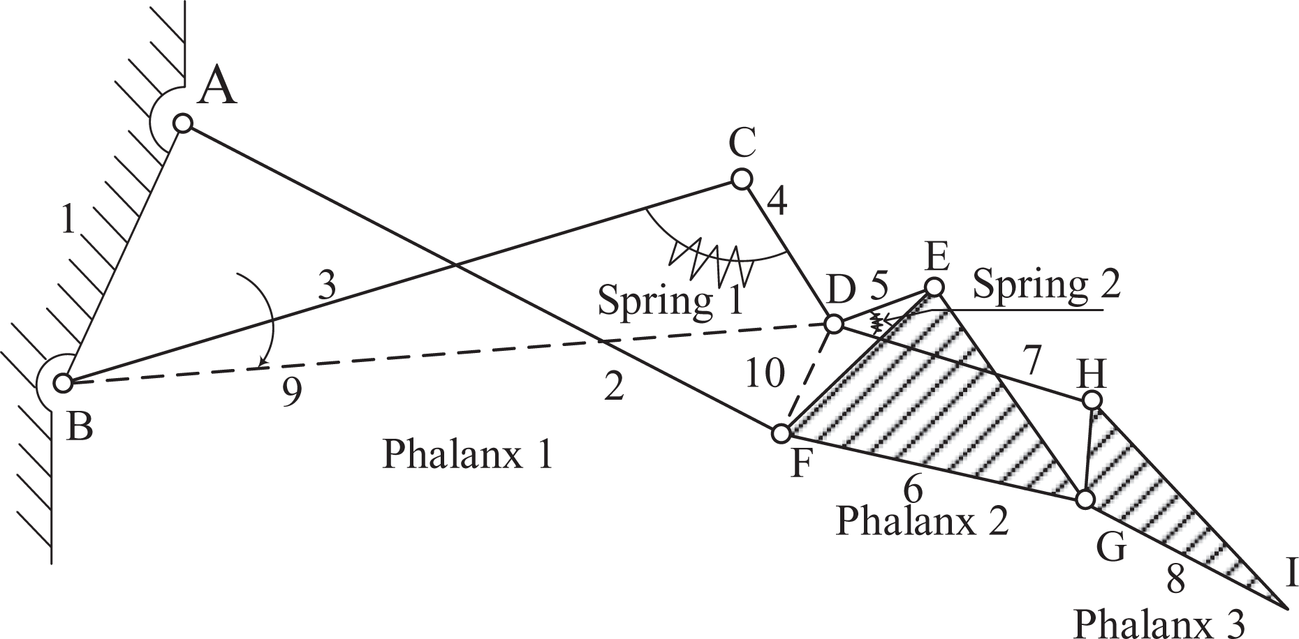
The underactuated finger mechanism proposed in this article is shown in Figure 1, including eight links and two torsion springs. Link 1 is the base, while link 2, link 6, and link 8 represent the three phalanxes. A, B, C, D, E, F, G, and H points are rotational joints. The torsion spring 1 is located between link 3 and link 4, and it rotates around joint C. The torsion spring 2 is located between link 5 and link 7, and it rotates around joint D. The only motor is installed on point B and drives link 3 directly.

A fully rotational joint connecting finger mechanism proposed in this article.
When the finger begins to grasp objects, the motor rotates clockwise, drives link 3 through joint B, drives link 4 through joint C, drives link 5 and link 7 through joint D, and drives link 6 (phalanx 2) and link 2 (phalanx 1) through joint F. Link 6 (phalanx 2) and link 7 drive link 8 (phalanx 3) to move through joint G and joint H, respectively. When the finger contacts with the object completely, the enveloping grasping is finished.
In Figure 2, a finger is built using the proposed mechanism. Besides, a test bed named Minzu University Hand is also developed. As shown in Figure 3, the Minzu University Hand has three same underactuated fingers with the proposed mechanism. These three fingers can change relative positions around the flat palm according to different catching objects.

A prototype finger built in Minzu University with the proposed mechanism.
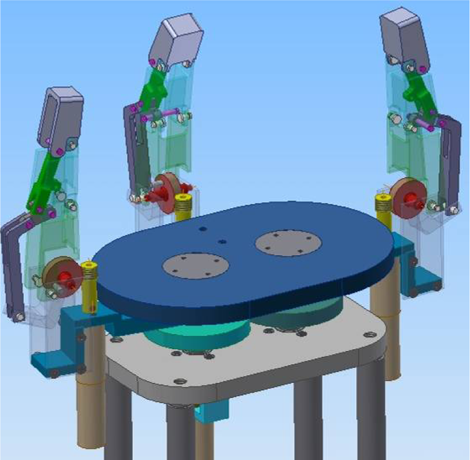
Scheme of a three-finger hand (Minzu University Hand) with the proposed mechanism.
Equivalent mechanisms deriving
An underactuated finger mechanism always needs many links and complicated structure to fulfill the underactuated motion, for example, the proposed mechanism as shown in Figure 1. Therefore, underactuated finger mechanism gives an open problem of analysis and design for this kind of complex mechanism.
In this article, a method based on the law of minimum resistance is proposed. The minimum resistance law indicates that a mechanism with more degrees of freedoms than the number of driving links will move along the direction of minimum resistance. Using the minimum resistance law, the proposed method derives some equivalent mechanisms according to different positions of the underactuated finger mechanism (i.e. the different contact conditions of the target object). These equivalent mechanisms usually are very simple mechanisms, for example, four-bar linkage. Therefore, analysis and design of the complex mechanism can easily fulfill according to these simple equivalent mechanisms.
The initial state of the finger mechanism, as shown in Figure 4, is in free state generally, that is, all the phalanxes have no contact with any object. Obviously, when the finger is in free state, since the resistance of phalanx’s forward movement is zero in theory, smaller than spring deformation, the springs will keep the initial length and have no deformation. In this case, the links connected by spring are equivalent to a fixed link, and it can be regarded as a virtual link. Both link 3 and link 4 can be regarded as a virtual link 9, namely, dashed line BD as shown in Figure 4. Links 5, 6, 7, 8 and spring 2 can be regarded as another virtual link 10, namely, dashed line DF as shown in Figure 4. Therefore, the proposed finger mechanism can be simplified to an equivalent mechanism, namely, four-bar linkage ABDF as shown in Figure 4.
Equivalent finger mechanism in different states.
When phalanx 1 touched the object, due to the restrictive effect of the object, link 2 (phalanx 1) stops rotating, while phalanxes 2 and 3 are still in free state. Obviously, the resistance of pressing the object by phalanx 1 is bigger than deformation of spring 1, the torsion spring 1 is stretched. Because phalanx 2 and phalanx 3 are in free state, spring 2 will have no deformation, links 5, 6, 7, 8 and spring 2 can still be regarded as the virtual link 10. At this point, the finger mechanism can be simplified to an equivalent mechanism: four-bar linkage BCDF as shown in Figure 4.
When phalanx 2 touched the object, due to the restrictive effect of the object, link 6 (phalanx 2) stops moving, link 8 (phalanx 3) keeps moving through motor driving. When link 4 drives links 5 and 7 through joint D, spring 2 is stretched. Thus the proposed finger mechanism becomes a six-bar linkage, and it can also be considered as two-cascaded four-bar linkages BCDE and EDHG as shown in Figure 4.
When phalanx 3 touched the object, due to the restrictive effect of the object, link 8 (phalanx 3) stops moving, links 6 (phalanx 2) and 2 (phalanx 1) cannot move either, that means the grasping movement is finished.
The deriving procedure reveals that the proposed underactuated mechanism is essentially driven by some simple equivalent mechanisms at different grasping stages. Therefore, the kinematic analysis of the finger mechanism can be easily fulfilled with these simple equivalent mechanisms, as described in the following section.
Kinematic analysis
In order to analyze the positional kinematics of the finger at different stages (i.e. the different contact states of the target object), the kinematic analysis of the equivalent mechanism of each stage is carried out.
In stage 1, without any external contact, the equivalent mechanism is a four-bar linkage ABDF as shown in Figure 5. li refers to the length of link i, i = 1, 2, … , 14. l9 indicates the length between point B and point D and it can be considered as the length of link 9. l10 indicates the length between point D and point F and it can be considered as the length of link 10. θi refers to the angle between x-axis and link i, i = 1, 2, … , 12. δ1 is the angle between x-axis and link 1, δ4 is the angle between link 9 and link 3, and θs1 is the initial angle of the spring 1.

Completely free state.
The four-bar linkage ABDF can be considered as a closed vector polygon, and the motion parametric equation can be deduced as

where
According to the motor rotation angle θ3, θ2 and θ10 can be calculated using equation (1) as
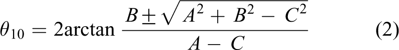

where A = l9 cos θ9 − l1 cos δ1,
In stage 2, phalanx 1 touched the object while phalanxes 2 and 3 are kept free, the equivalent mechanism is a four-bar linkage BCDF as shown in Figure 6. θ2 indicates the angle between link 2 and positive of x-axis. l11 indicates the length between point B and point F and it can be considered as the length of link 11.

Phalanx 1 was constrained.
The four-bar linkage BCDF can be considered as a closed-vector polygon, and the motion parametric equation can be deduced as

where l11 and θ11 can be calculated using equations (5) to (7) as


According to the motor rotation angle θ3, θ4, and θ10 can be calculated using equation (4) as


where
The angle of torsion spring 1

When θ4 is obtained, θs1 can be calculated using equation (10).
In stage 3, both phalanxes 2 and 3 touched the object, while phalanx 3 is kept free, the equivalent mechanism is two-cascaded four-bar linkages BCDE and EDHG as shown in Figure 7. l5, l8, and l12 refer to the length between point D and point E, point I and point G, point B and point E, respectively. l12 can be considered as the length of link 12. δ2, δ3, and δ7 are the angles between EF and FG, EG and FG, BF and EF, respectively. θs2 indicates the angle of torsion spring 2.

Phalanxes 1 and 2 were constrained.
The four-bar linkage BCDE can be considered as a closed-vector polygon, and the motion parametric equation can be deduced as

where
According to the motor rotation angle θ3, θ5 and θ4 can be calculated using equation (11) as

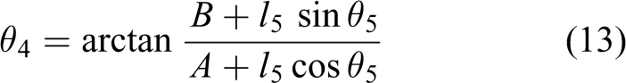
where
The four-bar linkage EDHG can be considered as a closed-vector polygon, and the motion parametric equation can be deduced as

where
When θ5 is calculated using equation (11) according to the motor rotation angle θ3, θ7 and θ8 can be calculated using equation (14) as

where
Limiting positions solving
In this article, the motion range of the finger mechanism is calculated by solving the forward motion limit of each equivalent mechanism. Analysis and solving process is described as follows. When the finger is in free state as shown in Figure 8, phalanx 1 will reach the limiting position when links 2 and 10 are in collinear positions. AF2D2B is the upward limiting position, AF1D1B is downward limiting position, and γ1 indicates the maximum motion range of phalanx 1 in this state.

The limiting position in free state.
According to Figure 8

where
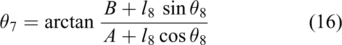
When phalanx 1 reached the limiting position, this will be the initial position of the second equivalent mechanism. Phalanx 2 can keep moving forward with the action of equivalent mechanism BCDF, and it will reach the limiting position when links 4 and 10 are in collinear positions (as shown in Figure 9). Therefore, the maximum motion range of phalanx 2 is γ2.
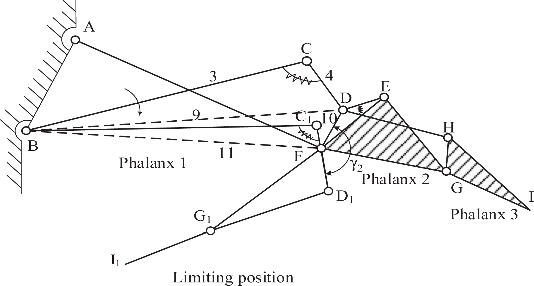
The forward limiting position of phalanx 2 when phalanx 1 reached limiting position.
According to Figure 9

where
When phalanx 2 reached the limiting position, this will be the initial position of the third equivalent mechanism, the motor angle
As shown in Figure 10, when BCDE reaches the limiting position, the motor angle is

The limiting position of BCDE when phalanx 2 reached limiting position.


Substituting
As shown in Figure 11, EDHG reaches the limiting position when ED1H1 in a line.

The limiting position of EDHG when phalanx 2 reached limiting position.
According to Figure 11

where
Numerical simulation
In order to verify the correctness of evaluation methods of the kinematics equation and limiting positions, and verify the performance of the proposed mechanism, the numerical simulation is carried out using MATLAB in this article.
The simulation finger size is humanoid; the dimension and structure parameters, respectively, are shown in Tables 1 and 2; lpi indicates the length of the phalanx shell; and hp indicates the height of the phalanx shell (as shown in Figure 1). The design results are shown in Figure 12.
Dimension of the finger shape.

Structure parameters of the finger mechanism.


Sketch of the finger mechanism proposed in this article.
According to the evaluation method of limiting position in described in section “Kinematic Analysis,” the three phalanxes’ reachable space are obtained as shown in Figure 13, where

Reachable space of the finger mechanism.
In this article, the whole process of grasping a cylindrical object is also simulated. Supposing the finger begins to grasp from the pose of horizontal straighten out (as shown in Figure 14), at this point the motor’s initial driven angle θ3 is 90°, the initial angles of θ2, θ4, θ5, θ6, θ7, and θ8 are −8.0°, 8.5°, −17.1°, 0°, 0.5°, and 61.2°, respectively. The initial angles of θs1 and θs2 are 81.5° and 16.68°, respectively. The radius of the cylinder is 30 mm, and the center coordinates are (3.5, −44.2). Let driven angle θ3 be continuously added with the step size of 5°, the simulation result of the fingers is shown in Figure 14. In Figure 14, the object is in the grasp range and it can be completely grasped by the finger. In addition, the grasp trajectory is smooth and uniform.

Simulation result of the grasping process.
Figure 15 shows a grasping sequence of the underactuated finger mechanism, where Figure 15 shows that phalanx 1 reaches the object when θ 3 = 60.0°, Figure 15 shows that phalanx 2 reaches the object when θ 3 = 53.0°, Figure 15 shows that phalanx 3 reaches the object when θ 3 = 40.0°.

A grasp sequence of the designed finger.
Conclusion
In this article, a new type of fully rotational joint underactuated finger mechanism is proposed. In order to realize the kinematic analysis of the complex mechanism, a new method based on the law of minimum resistance is presented, which can be used to derive the equivalent mechanisms in different stages and then achieve the kinematic analysis. The kinematic equations of the mechanism are derived by the proposed method, and the kinematic limiting positions of each equivalent mechanism are obtained. Finally, the performance of the mechanism and the kinematics analysis method are verified by programming in MATLAB. The simulation results show that the proposed method can solve the kinematics of the underactuated finger mechanism easily, and the proposed mechanism can achieve grasping smoothly and uniformly in a large range of space.
Footnotes
Declaration of conflicting interests
The author declared no potential conflicts of interest with respect to the research, authorship, and/or publication of this article.
Funding
The author disclosed receipt of the following financial support for the research, authorship, and/or publication of this article: This work was funded by the NSFC projects (No. 51375504) and the Program for New Century Excellent Talents in University.