
Abstract
Industrial robots have been widely used in many areas for the properties such as low cost, high flexibility and relatively large working space. The low absolute accuracy and low stiffness, however, limit the application in high precision areas. This article presents an approach for industrial robots that overcomes the inaccuracy of robotic path in offline programming. Robot Sensor Interface of KUKA robot controller makes the error compensation available. First, the compensation performance of the KUKA KR5 arc robot is investigated and the straight-line and circular arc path compensation strategies are proposed. Besides, an error compensation algorithm is proposed to generate the compensation values as well as to deal with the oscillation of real-time compensation. Finally, experimental results using a KUKA KR5 arc robot verify the correctness and accuracy of the approach.
Introduction
Industrial robots have been widely used in the field of industry so far due to their lower price, the larger working space, high degree of automation and so on. Most of the robot applications, however, are not involved in high precision fields, such as handing, welding, painting, assembling and so on. The high repeatability of industrial robots represents for those tasks. 1 Nevertheless, the industrial robots contain lots of errors, such as mechanical errors, thermal errors and so on.
Moreover, the stiffness of today’s industrial robots is very low. Consequently, the error is particularly large especially when the robots load weights. The dominant contribution factor for this is the joint compliance, such as gear transmission elasticity. 2 The industrial robots, hence, have limitation on the fields of precision path control. All these factors mentioned earlier account for their lower absolute accuracy.
Due to the advantage of the reduction of the downtime on the production line, the offline programming has been more and more extensive. Some programming methods based on virtual reality are proposed to provide programmer-safe environment in programming 3 as the robot can be programmed in virtual environment, 4 while the low absolute accuracy restricts the application.
To solve these aforementioned problems and improve the absolute accuracy, a common approach that can eliminate the errors caused by the mechanical errors is to calibrate the robots using kinematic models. 5,6 The most widely used model is the Denavit–Hartenberg (DH) model. 7 Similarly, to compensate the robot deformation that is caused by force acting on the end of the robot manipulator, a stiffness model is used 8 –10 to apply robot stiffness identification.
Although the usage of these models and offline compensation methods improves the absolute accuracy of robots, the error varies from different positions and postures in the working space. It is impossible to obtain the accuracy requirements for the whole working space. These methods can only take as much as dispersed points to calibrate in the workspace. Consequently, the selection of calibration lattice in the workspace has a great influence on the robot final accuracy. The accuracy out of these selected points is not particularly high. Additionally, this calibration method is relatively time-consuming, which needs large amount of computations.
There are also some methods to solve the problem. Chiba et al. 11 have proposed a method for rapid manipulator path planning that is able to satisfy the design time constraints. A flexible multisensor positioning system was proposed in the study of Roebrock. 12 The system puts forward a multisensor frame structure to realize measurement using different kinds of sensors and solves the positioning problem of the tool of robots rather than solving the path accuracy when performing path tasks. An offline path correction is presented in the study of Roebrock and BÃűhnke 13 to improve the path accuracy. The offline method is divided into a measurement run and an application run, which is time-consuming and obtains a low accuracy as well. In the study of Zi et al., 14 the sliding mode control is utilized to control robots, through which higher trajectory accuracy can be obtained after the control system is stable. Zhao et al. 15 proposed a method to correct a pre-planned path through an iterative learning control method. Wang et al. 16 proposed an approach used for trajectory or contour tracking with the goal of supporting noncontact robot machining applications. An error analysis of cooperative cable parallel manipulators is analysed in the study of Qian et al., 17 which provides a way of solving the effect of force.
In this article, an online real-time compensation method based on a laser tracker is presented. This method aims at increasing the accuracy without precise calibration. By comparing the real-time data of robot measured by an external measurement system (laser tracker) with the theoretical coordinate values in robot offline programming when executing path tasks, the error values of the robot can be calculated through the proposed path compensation strategy. By a real-time mechanism, compensation values at each moment can feed back to the robot in real time. Industrial robots can compensate for these errors through the compensation mechanism relatively quickly. The errors resulting from robot loads can also be compensated during executing path tasks, such as robot manufacturing and machining.
This article is divided into six sections. In section ‘System overview,’ the online measurement and control compensation system are presented and the KUKA Robot Sensor Interface (RSI) is introduced. In section ‘Robot path compensation’, researches on the compensation performance of the KUKA robot are presented. Besides, the path compensation algorithm and strategy are presented. Experimental design and validation are presented in ‘Experiments’ section. Finally, the last section gives the conclusions.
System overview
System structure
The online real-time compensation system is comprised of an industrial robot, a laser tracker, a computer and the measurement compensation software program. The overall structure is shown in Figure 1. The personal computer (PC) communicates with the robot via Ethernet. Simultaneously, PC communicates with the FARO Laser Tracker XI, FARO Technologies, Inc. via Ethernet. The software program was made in C++ language based on Microsoft Foundation Class (MFC). The open laser tracker interface for secondary development allows us to realize continuous measurement. The function of the PC software program is mainly to receive data from the robot, read the measured values of the laser tracker, perform compensation algorithm and simultaneously transmit compensation data to the robot in real time. If the robot reaches the required accuracy that we expect to achieve during performing path tasks, the software doesn’t execute the computational compensation program. That is to say, we don’t give the robot compensation values. The laser tracker runs in continuous measurement mode. Figure 2 presents the relationship between different coordinate systems. ObXbYbZb, OtXtYtZt and OeXeYeZe are, respectively, the robot base coordinate system, the laser tracker coordinate system and the robot tool coordinate system at the robot end effector. The compensation values calculated in the laser tracker coordinate system should be converted to the robot base coordinate system. The flow block diagram is shown in Figure 3.

System set-up.

Relationship between different coordinate systems.

Flow block diagram.
The program runs using multiple threads because it simultaneously receives the information from the robot and laser tracker. After processing these data, it sends the information with the Extensible Markup Language (XML) format to the robot.
Robot sensor interface
KUKA RSI enables the robot controller to communicate with external systems, 18 which can exchange data via Ethernet. The movement or path of robots can be affected or guided by the corresponding data received from external systems. The exchange data format and the communication must be configured in the robot controller. And data transmission must be strictly in accordance with XML format, which enables data between different systems to be compatible.
The characteristic of RSI is that the signal processing must be in the 12 ms interpolation cycle and is parallel to robot program execution (see Figure 4). If the robot fails to receive data within 12 ms, an error of late packets occurs. When the error counts reach the set threshold in the configuration file, the communication interrupts. Thus, the data exchange between the robot and the external devices is relatively real time.

Robot Sensor Interface execution diagram.
Robot path compensation
Single error compensation performance of KUKA robots
Through KUKA RSI, the errors can be compensated. First, the single error compensation experiment aims at investigating the compensation performances of KUKA robots. In this section, we set 0.5 mm, 0.7 mm and 1.0 mm compensation values, respectively, in the directions of X, Y and Z with respect to the laser tracker coordinate system. The experimental results obtained are shown in Figure 5.

Results of single error compensation.
It is found that the error compensation of the robot has hysteresis. This is because the robot’s electronic and mechanical components are hysteretic. Hence, it is not able to compensate the error with an extremely high speed. It can be found that the compensation cycle is approximately 500 ms.
Path compensation strategy
Robots are increasingly using offline programming, which requires high absolute accuracy. Because of industrial robots’ errors, the absolute accuracy is low and there are deviations between the actual path and theoretical path while executing tasks. When the robot loads weights, the low stiffness leads to considerable deviations as well. Therefore, the deviations caused by these factors must be detected and be compensated either. As the straight-line and circular arc paths are the most basic components of robotic path tasks during robot running programs in practice, we will propose a straight-line path and a circular arc path compensation strategy in the following section.
Straight-line path compensation strategy
The straight-line path compensation strategy proposed in this system is shown in Figure 6. The straight-line path is assumed as the theoretical path we need. The end points of LIN (it is the line path command of KUKA robot) command in robot controller using offline programming is PA and PB. However, due to the low absolute accuracy and low stiffness of industrial robots, the robot tool centre point (TCP) can’t execute the path exactly according to the coordinates in robot controller, namely line PA-PB. While executing path tasks, the position at each moment is assumed to be P(t), which can be measured using the laser tracker. The perpendicular foot


Straight-line path compensation strategy.
By solving equations (1) and (2) simultaneously, the theoretical position at each moment can be described as

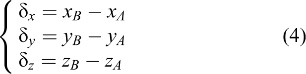
where, δx, δy and δz are the coordinate difference between two end points, namely
Circular arc path compensation strategy
In the circular arc path tasks, the start point, middle point and end point at the CIRC (it is the Circular arc path command of KUKA robot) program are, respectively,

Circular arc path compensation strategy.


where R is the radius of the circle. According to equations (5) and (6), the coordinate values of the centre and the radius of the circle can be described as


where, A1-D1, A2-D2 and A3-D3 are a series of parameters as follows

The


The

As shown in Figure 7, in the circular arc path tasks, the intersection


Hence, the theoretical position during the circular arc path tasks at each moment, namely

As the robot deviation is usually less than the radius of planned circular arc path tasks, hence the condition in the bracket, here, makes the
Path real-time compensation algorithm
From the aforementioned discussion, errors at each moment can be obtained during both straight-line and circular arc path tasks. Assume that the homogeneous transformation matrix between the robot base coordinate system and laser tracker system is

where n, o and a are, respectively, the normal vector, the direction vector and the approach vector, which represent the rotation relation between the robot base coordinate system and laser tracker coordinate system. The vector p shows the translation relation. The relationship can be expressed as follows

where Prob and Ptracker are, respectively, the position at the robot coordinate system and laser tracker system. Therefore, the position at the laser tracker coordinate system can be converted to robot base coordinate system through the following equation

Hence, the errors at each moment during the path tasks in the laser tracker coordinate system can be converted to the errors in the robot base coordinate system, as follows

where
Because the robot executes a number of continuous tasks, it is necessary to compensate the errors in the process of performing continuous trajectory tasks. However, due to the hysteresis of error compensation, if real-time error compensation values are sent to robot directly via RSI, it will make the robot work with oscillation. It is because that the compensation values sent to robots will take about 500 ms to complete the compensation process, and the errors measured next will accumulate to the former unfinished ongoing compensation. Thus, a proportion-integral-derivative (PID) control algorithm is used to make the real-time compensation possible.
First, the robot control algorithm structure (see Figure 8) was proposed. Each moment in the process of continuous trajectory tasks, the real-time measurement values of the laser tracker are compared with the theoretical coordinate values, and the compensation values are obtained by calculating. With the coordinate system transformation matrix, these values can be converted to the robot base coordinate system, which are sent to the KUKA robot every 12 ms. The control algorithm is as follows

Robot control algorithm structure.

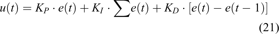
where KP, KI and KD are, respectively, the proportion, integral and differential coefficient of the PID controller; e(t) is the path error in the robot coordinate system and u(t) is the output value of the PID controller, namely the feedback value to robot controller.
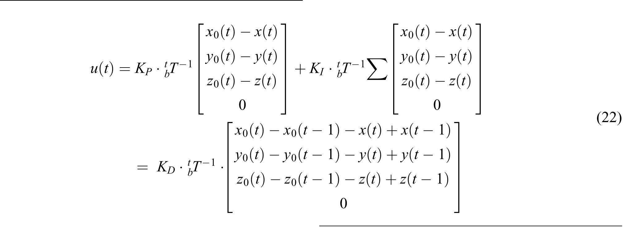
Substituting equations (3) and (15) into equation (21), the compensation value at each moment is obtained as follows
In order to compare the results of single error compensation, we also set 0.5 mm, 0.7 mm and 1.0 mm compensation values, respectively, in the directions of X, Y and Z with respect to the laser tracker coordinate system. The results of real-time compensation are shown in Figure 9.

Results of real-time error compensation.
As shown in Figure 9, different control coefficients result in different effects. Here, a simple proportional controller is utilized. The results show that when the proportional coefficient KP is set to 0.05, the oscillation is small enough and the compensation time is short enough as well.
In the path of the offline programming, the usage of the compensation algorithm mentioned above at each moment during the path tasks can achieve very good accuracy. Experimental design and validation will be stated in the ‘Experiments’ section.
Experiments
From what has been discussed earlier, the error compensation performance of the KUKA KR5 arc industrial robot is known. The following discussion focuses on the error compensation on the process of the path tasks.
As we all know, the robots’ absolute positioning accuracy is low. So, when robots execute trajectory tasks, they cannot perform accurately in accordance with the coordinates in the offline program, hence, resulting in deviation.
In this section, the experimental results will be analysed by comparing the online real-time compensation method with the process without compensation. A KUKA KR5 arc Industrial Robot and FARO XI Laser Tracker are used for experimental validation. A laser tracker target base with magnetic force is fixed at a metal plate, and the metal plate is installed at the robot flange. The laser tracker SMR target is mounted at this base by magnetic force. The absolute distance measurement accuracy of the laser tracker is 20 μm + 1.1 μm/m. The measurement frequency here is set to 100 Hz, that is, we can obtain 100 data per second. The set-up of experiment is shown in Figure 10.

The set-up of experiment.
Comparison experiment of online compensation and offline calibration
In order to compare with the accuracy of online compensation approach proposed in this article and the offline calibration approach, the online compensation and offline calibration experiment are executed, respectively. The offline calibration method, here, refers to the study of Liu et al. 20 Fifty-one points in the robot workspace are selected to calibrate the robot. For comparison, the selected 51 points are also executed according to the online compensation. The results are illustrated in Figure 11.

Comparison of positional error between online compensation and offline calibration.
Without compensation, the maximum positional error is about 1.783 mm and the error can be reduced to 0.600 mm after offline calibration. After online compensation method proposed in this system, the maximum positional error is 0.016 mm, which meets the high accuracy requirements of the fields. Hence, the accuracy obtained in the system is better than offline calibration.
Experiment of robot executing LIN command without load
When KUKA robot executes LIN commands, straight-line paths are generated. The coordinate values of the robot TCP in the robot program are executed according to the robot kinematic model, so there are errors between the actual path that the robot executes and the path we actually planned. In this section, the KUKA robot executes a LIN command to perform straight-line path and to validate the accuracy of the compensation method. The start and end points of the planned straight-line path in the external measuring coordinate system (laser tracker) are P A (2256.000, −122.000, 40.000) and P B (2444.000, −201.000, 90.000). The results are illustrated in Figures 12 and 13.

Results of straight-line path real-time compensation without load.

Straightness errors of line without compensation.
Here, we draw a straight line whose start and end points are the points robot actually executes and we define the distance errors deviated from this line as the straightness errors. As shown in Figure 13, without compensation, the straightness error of the straight-line path is relatively good. However, the maximum straightness error also reaches 0.206 mm at a length of about 210 mm.
Besides, as shown in Figure 12, the maximum errors in the X, Y and Z directions are 0.337 mm, 0.562 mm and 0.404 mm, respectively, and the distance error is 0.758 mm. The error of Y direction is larger than other directions in the planned path, and such low accuracy limit robots are to be used widely in precise fields. During the compensation stage, the errors are extremely declined. After compensation, the maximum errors in the X, Y and Z directions are 0.042 mm, 0.061 mm and 0.087 mm and the distance error is less than 0.107 mm.
In the study of Tao et al., 21 an online preprocessing implementation to calibrate robots is proposed. The accuracy of the maximum position error is 0.974 mm. The accuracy in our system is higher, whose maximum position error is 0.107 mm during path tasks. Moreover, the approach here is obtained in the robot path tasks; that is, the accuracy is obtained in the continuous path process, rather than in the discrete process. Such accuracy is more valuable in the actual use of industrial robots.
Experiment of robot executing LIN command with load
The aforementioned experiments are carried out under the condition of no load. Industrial robots, however, are often used as a carrier for other tools. For example, when we use robots to process parts, the machining tool is installed at the end of the robots. The machining force is acted on the robot. When robots are used to assemble parts, the weight of different parts is acted on them. Therefore, robot load is a very important factor in the use of robots. The following experiments are designed to verify the accuracy of this system while executing path in the case of robot with load.
The rated payload of KUKA KR5 arc robot is 5 kg. We install 4 kg load at the end of the robot and the robot perform LIN command path tasks. The results are shown in Figure 14.

Results of straight-line path real-time compensation with load.
Without compensation, mainly due to the low stiffness of the robot and the robot’s mechanical errors, the accuracy of path tasks under load condition is relatively low. The trend of errors is similar to the condition without load and there is a similar linear increase. The maximum errors in X, Y and Z directions, as shown in Figure 14, are 0.541 mm, 0.803 mm and 0.863 mm, respectively, and the distance error is 1.251 mm, which are much larger than the case of no load. After compensation, the accuracy of path is improved with maximum errors of 0.046 mm, 0.061 mm and 0.092 mm in X, Y and Z directions, respectively. The maximum distance error is reduced to 0.110 mm. The accuracy after compensation is quite close to the case without load. Hence, the performance of the proposed system above is good enough in the case of robot performing straight-line path with load.
Experiment of robot executing CIRC command without load
In this section, the robot runs CIRC command to perform a circular arc task. The planned circular arc path in the laser tracker coordinate system is calculated from C1 (2256.000, −122.000, 40.000), C 2 (2306.000, −72.000, 70.000) and C 3 (2356.000, −130.000, 100.000) and the centre can be calculated according to equation (7), which is (2305.728, −130.630, 69.837). The results are illustrated in Figure 15.

Results of circular arc path real-time compensation without load.
Without the real-time compensation strategy, the errors are large. The errors without compensation vary more tremendously compared with the straight-line path. The errors in X and Y directions are larger than Z direction. The maximum errors in X, Y and Z directions are 0.530 mm, 0.393 mm and 0.281 mm, respectively, and the distance maximum error is 0.575 mm.
The compensation values in circular arc path at each moment can be calculated according to equations (15) and (22). With the path compensation algorithm, the accuracy of the circular arc path is improved greatly. The errors can be reduced to 0.114 mm, 0.121 mm, 0.163 mm and 0.200 mm. Furthermore, the mean errors decrease significantly as well. From Figure 15, we can also see that the compensation errors are larger when the uncompensated path errors change significantly. The spikes of errors in both uncompensated and compensated conditions in Figure 15 explain that.
Experiment of robot executing CIRC command with load
In this section, robot performs the circular arc command mentioned earlier and the real-time path compensation is executed with a load of 4 kg. The results are illustrated in Figure 16. As the straight-line path tasks, the error during circular arc path tasks is also larger in the condition of with load than without load, and there is a similar linear increase. The low stiffness is responsible for that. After compensation, the errors can also be eliminated dramatically. The maximum errors in the directions of X, Y and Z are 0.099 mm, 0.141 mm and 0.162 mm, respectively, and the distance error is reduced to 0.218 mm. Hence, the errors after online real-time compensation are similar in both conditions, which means the system can achieve high accuracy with load during circular arc path tasks.

Results of circular arc path real-time compensation with load.
Conclusions
This article presents an online real-time compensation approach for industrial robots to execute precise path tasks. The laser tracker was used to measure the position each time, and the straight-line and circular arc path compensation strategies were proposed and the PID control algorithm was used to calculate compensation values that the robot can compensate for every 12 ms. The oscillation of real-time compensation is solved through the PID control. The method didn’t need accurate offline calibration and can reach relatively high accuracy. Besides, this system also reaches high accuracy when the robot loads weights. Consequently, the approach didn’t need robot stiffness identification when considering the load.
In further work, the compensation method will be tested in more complex conditions, and the attitude errors should be considered and compensated.
Footnotes
Declaration of conflicting interests
The author(s) declared no potential conflicts of interest with respect to the research, authorship, and/or publication of this article.
Funding
The author(s) disclosed receipt of the following financial support for the research, authorship, and/or publication of this article: This work is supported by the National Natural Science Foundation of China (no. 51275350) and the Marine Science and Technology Project from the Tianjin Marine Bureau (no. KJXH2014-08).