
Abstract
The use of precision actuators in robotic arm comes from the need to ensure the resulting accuracy of the robot at the maximum speed of movement. The replacement of actuators by means of electrical module allows the use of carrier body of the module for gripping flanges or other modules. Development of new modules is based on the requirement of providing a complete solution for the customer’s needs. After the development of new modules, the producer checks the parameters, receives feedback, and uses the authentication options in the independent workplaces, which can provide impartial results. Based on this data, manufacturers can optimize their solutions and deliver the products to market, complying with not only their vision but mainly the needs of customers. This article describes how to verify the characteristics of the modules used in the construction of robotic wrist. It primarily focuses on verification of the accuracy of results and repeatability of position of the wrist on output flange end module. In addition, it presents the design of the testing stand and selection methodologies of measurement. The declared values are compared with the values measured during verification.
Introduction
The positioning actuator is conceptually built as an electric servomechanism for controlling the position mechanism of the machine system, 1 which is built from precision gearboxes with stored output (shaft, flange) of precision roller bearings and servo motors in a structural and functional axial assembled unit built of the correctly dimensioned components. 2,3 Electric motor, gearbox, power semiconductor converters for power, motor controller and controller of speed or position are functionally crucial elements coaxial arrangement aggregates of positioning actuators (compact drive units). 4 Engine components are usually speed and position sensors; bearers of properties and parameters of the module are the output elements. Driving part of the actuator must allow four-quadrant operation in both directions of rotation and in both directions of torque influence. Actuator operates in closed loop, and feedback position control is either targeted (optimal positioning—manipulators, positioners, positioning tables, etc.) or monitored (time optimal positional adjustment, as soon as possible, follows the specified trajectory/specifying precise speed—robots, multi-axis machine tools, antennas, and monitoring systems, etc.). 5 Speed/velocity controls only expressway feedback that enables quick and precise monitoring of the specified speed. 6,7 System model of actuator, as show on figure 1, describes concept solutions of power part (motor with transformation mechanism for changing the kinematic parameters of movement – the speed of movement). At the same time, it describes the internal structure of the building actuator (complete block diagram), which is based on the system components (the basic of internal functions of module). 8,9
Digital spectrum modulation (DSM) is a newly developed series of modules, which is based on actuators. DS was manufactured by SPINEA Technologies (Prešov, Slovakia). 10 The module consists of precision cycloidal reducers TwinSpin TS 50 M, 70 TB, or 110 TB, specially designed winding, brake, speed sensor, and carrier body. 11 This module is primarily intended for use in end-axis manipulators and in positioning the production machines. Innovation of DSM with DS involves in replacing the standard actuator and new windings stored in aluminum housing special design. Windings were designed and produced by TG drives (Brno, Czech Republic). 12 The module casing is made of aluminum alloy EN AW 2017 with rectangular cross section. The back and underside of the aluminum body contains a system with coupling holes. The rear side of aluminum body contains a centering hole and a set of four threaded holes with the thread size ranging from M5 to M10. The underside of the aluminum body consists of a set of four through holes, a set of four threaded holes, and a pair of centering holes. Carrier modules are sized so that they can withstand the force load acting in the radial and axial direction as well as the action-induced torque and tilting movement. 13 DSMs are arranged according to their size range, which are identified as DSM 50, 70, and 110. The size range of the module is defined based on the diameter output flange reducer placed on the appropriate module. 10 System model for connecting modules of DSM with higher functional units describes the concept of solutions containing DSM module/modules, mounting flanges, connecting flange, output flange and also describes the basic principles of control, as shown in Figure 1.

System model for connecting modules.
Complete (theoretical) structure of higher functional unit made of DSM modules is derived from its general structure. The elements of the functional binding system (the internal functionality of the module) are demonstrated in the following 14 –17

On verifying the robotic wrist, it was understood that the modules used are of two sizes: DSM70 and DSM 50, and their output parameters are as follows
10
Rated output torque—18 and 50 Nm. Acceleration/braking output torque—36 and 100 nm. Maximum axial force—1.9 and 4.1kN. Rated radial force—1.44 and 2.8 kN. Maximum tilting moment—44 and 142 nm. Maximum lost motion—1.5 arcmin. Positioning accuracy—0.020 mm. Positioning repeatability—0.025 mm. Drift of pose accuracy (dAP) and repeatability—0.002 mm.
The verified robotic wrist, except module DSM 70 and 50, was configured, which includes two interconnecting flanges, as shown in Figure 2.

Assembly of robotic wrist in 3-D view.
Selection of measuring tests and their description
Selected measurement tests are based on ISO 9283 standards focusing on “Manipulating industrial robots—Performance criteria and related test methods.” 18,19 Overview of selected tests of individual performance characteristics is shown in Table 1. Methodological sheets were developed for the proposed system of measurements and tests. From methodological sheets, after replenishment, the measured values can easily generate a set of incremental measurements, as part of the measurement protocol wrist.
Selected measurement tests.

AP: pose accuracy; RP: pose repeatability; dAP: drift of pose accuracy; dRP: drift of pose repeatability.
Pose accuracy (AP) is the difference between a position that is programmed and the average of the positions of end-member robot (wrist), which have indeed been reached. Into the programmed position, the end-member robot (wrist) must commute in the same direction. 18,19 The measuring system comprises three Heidenhain (Germany) MT25 sensors and one MT12 sensor, as shown in Figure 3. The three MT25 sensors are placed in three axes (x, y, z) orthogonal to each other. The fourth, the compensation sensor “k,” is placed in the direction of “y” axis. Sensor MT12 is used for measuring position of wrists in base position, after moving of wrist.
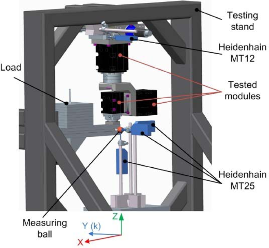
Location sensors in measuring workplace.
From the measured values, the AP is calculated in x-y-z axes from equation


The AP compensation sensor K in the y-axis

where xC, zC, yC, kC are the programmed values and xj, zj, yj, kj are the real (the measured) values. While


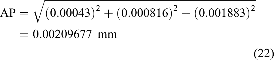
The resulting AP of the wrist is based on the equation

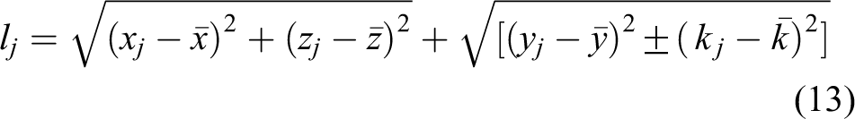
Pose repeatability (RP) expresses the degree of conformity between the place positions achieved after n-repetitive movements programmed to the same position in the same direction. RP is calculated from the measured values as the radius of the sphere whose center is under barycenter, as shown in the equation

where


For a cluster of n points, defined by their coordinates (Xj
, Yj
, Zj
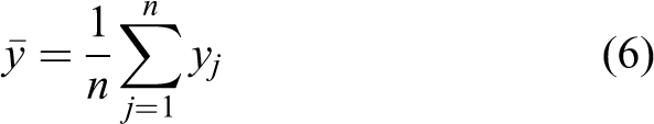
), the barycenter of that cluster of points is the point whose coordinates are the mean values
dAP and drift of pose repeatability (dRP) were measured using the parameters AP and RP. Testing was determined by the change in AP and RP with time. Characteristic drift of the position has been carried out under cold condition (i.e. prior to the test warming up traffic is not done), which lasted 8 h. dAP is based on the relationships


b. dRP is based on the relationships


Testing stand
Design of testing stand
The design of the testing stand is based on the requirements placement of your wrist with two or three degrees of freedom equipped with DSM modules in vertical and horizontal direction, as shown in Figure 4. 19 Testing stands use the measuring stand for the verification of performance actuators DS and DSH measuring 700 × 700−1700 mm. The material used for the testing stand is made of steel S235JRH as a closed square and rectangular profiles with a wall thickness of at least 4 mm. Testing stand is also found to be in linear axis. The tested modules (wrist) outside the measuring point serve in ejection, wherein the control program carries out the programmed movements of the module in the order. Linear axis comprises linear guideways Hiwin (HGW 15CC a HGR 15 R; Taiwan), ball screw Hiwin R08-25T2, DC motor Faulhaber 3257G024CR and planetary gear Faulhaber 38/1.

Location sensors in measuring workplace and realistic view of testing stand.
General view of the measuring workplace is shown in Figure 4. Placement robotic wrist is in a vertical direction. Load robotic wrist realized the value of 7.2 kg on the arm of 0.25 m, which represents a load of the value of 18 Nm. The speed of rotation of each module robotic wrist is set at 15 min−1.
Measurement procedure of the testing stand
Preparation for measurement
The temperature at the measurement place is maintained in the range of 20°C ± 2°C.
Wrist with 3 degrees of freedom is placed on a measuring stand in a vertical position.
Individual modules of the wrist are set to initial (zero) position.
On output flange, last module DSM 50 is placed with a set of weights of value 7.2 kg.
The axis of the last module is positioned to measure the sphere of diameter 30 mm.
Three touch sensors Heidenhain MT 25 have secured the touch at measuring sphere from three perpendicular sides. The fourth sensor Heidenhain MT 12 is placed in a position capable of detecting variations in measurements after leaving and subsequently returned the robotic wrist to the starting position.
Measurement procedure
Touch sensors will move from the surface of the measuring sphere to the starting position.
Robotic wrist after the start of measurement moves to from the measuring point about the value of 200 mm. Speed of movement is 100 mm/s.
Start of the program cycle of rotation and tilting of the individual modules wrist involve the following steps: – Step 1: The first module DSM 70 realizes rotation by the value +90°, second module DSM 70 realizes rotation by the value +90°, and third module DSM 50 realizes rotation by the value +90° at 15 rpm. – Step 2: First, second, and third modules will return to the starting position at a speed of 15 min−1.
Wrist returns to the measuring point, in which abut against the end stops. The speed of movement is 100 mm/s.
Touch sensors will be transferred from the starting position to the measuring position (they touch the measuring ball).
After stabilizing the sensors, which lasts for 3 s, four readings will be subtracted from in evaluation units Heidenhain VRZ 401.
Results and discussion
Pose accuracy
Graphical representation of measured data (AP) in the direction of the axes (x), (z), (y) and a correction (K) is shown in the graph of Figure 5.
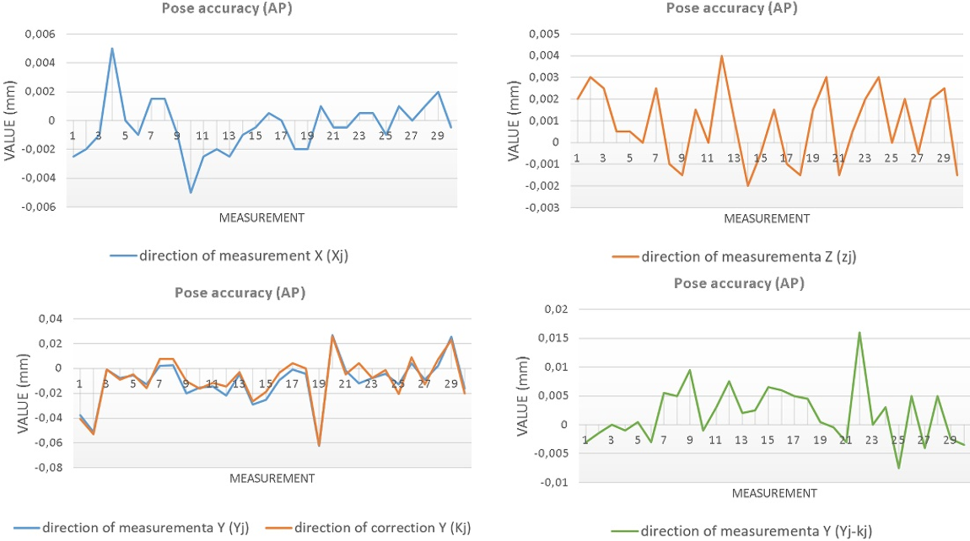
AP in axis (x, z, y). AP: pose accuracy.
After observing the 30 measurements at full load wrist, we came to the following averages (AP) as shown in Table 2.
Average—AP.

AP: pose accuracy.
Calculated (AP) is based on equation (9) and has a value
Pose repeatability
Graphical representation of measured data (RP) in the direction of the axes (x), (z), (y) and a correction (K) is shown in the graph of Figure 6.

AP in axis (x, z, y). AP: pose accuracy.
After observing the 30 measurements at full load wrist, we obtained the average (RP) as shown in Table 3.
Average—RP.

RP: pose repeatability.
Calculation (RP) is based on equation (10), giving a value

dAP and dRP
Drift of position has been carried out under cold conditions and lasted for 8 h. Of the 8 h, a 30-min interval was subtracted, resulting in realized measurements of 16 dAP and 16 dRP.
The dAP was calculated based on the relationships (14–17), giving a value


The dRP was calculated based on the relationships (18–21), giving a value:


Validate the parameters DSM modules used in the construction of the robotic wrist confirmed the demands placed on which, were imposed on during for the development. On the basis of realized measurements, it can be appreciated that the aluminum module has sufficient rigidity, resulting in the measured value of the accuracy. The measurements carried out during configuration consisted of two modules type series 70 and one type series 50. Completed verification concentrated mainly on finding the resulting positioning accuracy and repeatability. This was related to the need for a comparison of the proposed modules compared to standard type of actuators DS70 and DS50. Measurements confirmed that the verified modules DSM fully replaces the standard actuators of DS series. The basic advantage is the ability to simply attach the module to the flange or by other modules, in the standard DS series it was problematic. On the basis of the verification carried out by focusing on the drift of position, it was found that the modules do not lose their properties during the 8 h of work shift.
Placing your wrist in vertical direction verifies characteristic in second and in third modules. The parameters of the first module will be necessary to check the wrist in a horizontal direction. You will then need to implement measurements such as minimum posing time and static compliance.
Conclusion
Based on realized measurement of characteristic in modules assembled in the wrist with 3 degrees of freedom, we have come to the following conclusions:
Estimated average (AP) was not allowed to exceed the value of 0.005 mm (0.005 > 0.0018). The maximum value was not allowed to exceed the value 0.02 mm (0.02 > 0.016). On the basis of realized measurements, we can conclude that AP of the used modules is within the desired range.
Estimated average (RP) was not allowed to exceed the value of 0.0075 mm (0.0075 > 0.0066). The maximum value was not allowed to exceed the value of 0.025 mm (0.025 > 0.0245). On the basis of realized measurements, we can conclude that RP of the used modules is within the desired range.
The presumed maximum value of dAP and dRP was not allowed to exceed the value 0.002 mm (0.002 > 0.0019). On the basis of the realized measurements, we can conclude that dAP and dRP of the used modules is within the desired range.
Footnotes
Acknowledgments
This article is the result of the project implementation: 059TUKE-4-2014 Rozvoj kvality života, tvorivosti a motoriky hendikepovaných a starších osôb s podporou robotických zariadení.
Declaration of conflicting interests
The author(s) declared no potential conflicts of interest with respect to the research, authorship, and/or publication of this article.
Funding
The author(s) received no financial support for the research, authorship, and/or publication of this article.