
Abstract
The article is devoted to understand how to easily perform weight measurement of the workpiece in the course of handling the robot cycle, provided that the handling cycle of the robot is not a sufficient idle time. It is therefore necessary to find a time gap in the algorithm of motion, which would be suitable for such a measurement. This place is affected by the handling speed, acceleration, grip stability of the workpiece – it is necessary to exclude other dynamic effects on the measurement of weight. The authors suggest that one of the best ways to avoid systematic errors is to find a sufficiently large acceleration in the positive direction of the axis ‘z’ of the handling robot. The article describes how the authors performed a few weight measurements of the pieces in the dynamic mode, and finally the evaluating the accuracy of the calibration measurements with the help of the used measuring chain.
Introduction
Today there is robotization in almost every field of industry. Most of the earlier proposed and implemented robotic cells did not track the workpiece parameters even in the process of their production. Now, there is a need to monitor these parameters and to be able to manage them even in the time. In production is the need to apply some methods of measurement directly in the production process, without changing the algorithm itself. It should not change the algorithm due to the optimization of production. Just because of that it is necessary to transform some static measurements for the dynamic measurement so as to carry out the process of handling of products. 1,2
Dynamic measurement systems
In general, it is possible to divide the systems for static and dynamic weighing. When there is a static weight measurement, it is possible to measure the complete stabilization of the object. Dynamic measurements can be subdivided into three groups as follows: Discrete mass delivery systems Discontinuous totalizing weighers In-motion weighing systems
3
All of these dynamic measurements in general relate to the materials transported and not to direct measuring objects handled by robot. For this type of measurement, it is necessary to carry out measurements during the movement or somewhere in the best period of the movement itself.
Problem description
The majority of suppliers in the automotive (of course also other sectors) industry has its production set in the delivery way ‘just in time’. If there is a request for amendment of some operation in the scope of the production, it is almost necessary to extend the time of production. Some requirements for the integration of operations are necessary mainly to reduce the percentage of nonconforming products, at the time of production, and to carry out setting, in an appropriate manner, of the operations in the production process to eliminate failure. Another reason why there are emerging new demands for inclusion of new operation into the production process is that during the manufacturing process it is possible to find the relevant product that becomes nonconforming due to the wrong properties. The authors of this article are currently working on the integration of the control measurements of weight to an existing robotic cell in order to reduce the losses and improve the quality of the product. 4,5
One of the important properties in the rubber (tyre) industry is the measurement of the weight of the produced bead wire. When a bead wire with a nonconforming characteristic is detected, during the time of their production and handling, it is possible to reject them from the process, therefore stopping the production of a final product (tyre) that is nonconforming. The weight of the product is another important feature in addition to the dimensional characteristics. Bead wire is very often handled so that it is not possible static weight measurement (bead wire is still in motion). Time losses resulting due to the implementation of additional station (operation) for bead wire weight measurement would have adverse effect on production technology (temperature drop). Right here is the space for innovative approaches to the measurement of the weight within the movement time of the robot arm. 6
Experiment description
After studying the theoretical possibilities, we decided to perform an experiment to assess the possibility of measurement and evaluation during the movement cycle, to identify the most appropriate place for the measurement and consequently to evaluate the measurement accuracy. A manipulator robot, OTC Almega AX-V6, was chosen with the AXC control system which is designed mainly for handling and welding operations. A gripping mechanism of the robot we used with designed effector is shown in Figure 1 which was equipped with strain gauge. To grip the samples, we used the active pneumatic two-jaw parallel gripper phd 5300 which was controlled by robot using the electromagnetic valve. This experiment was built to achieve conditions close to those in production. 7

Effector with sensor.
A measuring cell was used with a strain gauge of EMS70, 1 kN, as shown in Figure 2, since the strain gauge is an important maximum load of the sensor. It is important because if the sensor is loaded over the permissible limit even for a short time (a few milliseconds), it is usually permanently damaged and cannot be repaired. The main parameters of the used sensor are as follows:
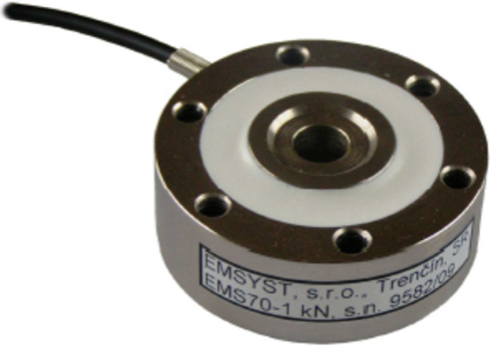
Strain gauge sensor used. 8
The nominal measuring range – 1 kN
Useable measurement range – 130% force strain (F.S.)
The maximum permissible measuring range – 150% F.S.
Sensitivity – 1.5 mV/V
The maximum error of the sensitivity and zero – 2% F.S.
The maximum error of the linearity and hysteresis – 0.2% F.S.
The temperature coefficient of the zero and sensitivity – 0.05% F.S./°C 10
Recommended voltage – 10 V 8
At the beginning, we chose a movement of robot by programmed path according to the algorithm (see Figure 3) where the time of the movement is not the sufficient idle time for static measurement. The movement of the robot is achieved by point to point (PTP) way where the trajectory of the movement between the points is a curved line that is optimized with respect to the drives. The whole trajectory is fairly chaotic in order to allow the analysis of suitable locations for the measurement of the measured data. The maximum speed of the robot over the scope of movement was set at 80% of its maximum speed, that is, 2 m/s. Maximal acceleration of the robot was in upward direction and reached 80% of the maximum possible value, that is, 2 m/s2. For the movement without load (only with a grip system), progress was measured (see Figure 4). 4

The trajectory of the robot movement.

Measurement during manipulation without load.
The vertical axis in the picture represents the output of the analogue-to-digital (ADC) converter which was 12 bit. The time scope of a movement which lasted 5 s has taken 1000 samples (5 ms/sample), which are located on the horizontal axis. Whereas, for the sampling used to run manual synchronization, it was necessary to find a prominent place in samples of measurements and synchronize the various waveforms. The most prominent place suitable for synchronization was the maximum peak (for the measurement of the sample 426). It is a place where the robot reached the top of the trajectory and there has been a change in the movement towards the ground. Therefore, samples with the load reach a peak with a very close value (2966), since at this point there is an effect of a weight negation.
We decided to test the samples with weights 500 g, 1000 g and 1500 g and, of course, without load. The sampling procedure was repeated 10 times for each load in order to determine the stability of the measurements. Number of measurements is insufficient for an accurate determination of the dispersion characteristics of the measurement, but it is sufficient to determine whether or not the methods of measurement is useable. The measurement procedure is as follows:

Measurement of no load.

Measurement with etalon 500 g.
Measurement with etalon 1000 g.

Measurement with etalon 1500 g.

Measurement of no load.
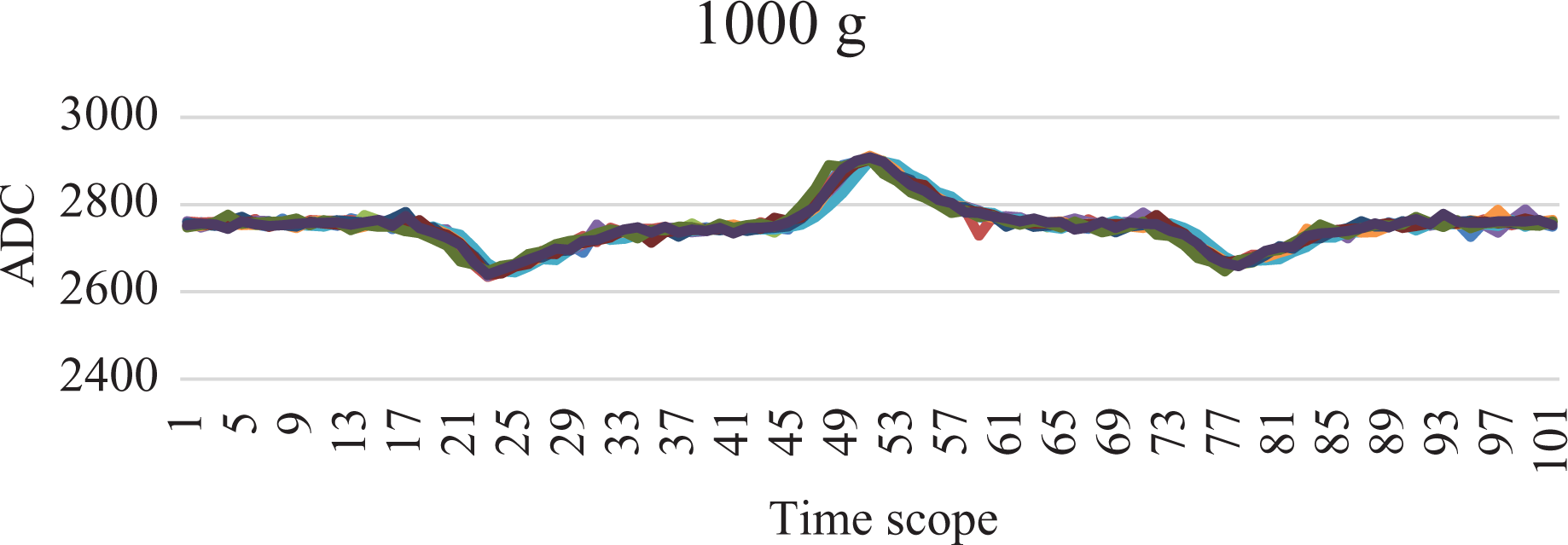
The figures do not demonstrate the entire scope of measurement but only 100 samples, whereas the sample no. 50 is a synchronization peak. According to analysis of the diagram and all data, the most appropriate scope of trajectory for measurement is the part of rapid acceleration in the upward direction. It is a place where the restriction of vibration of all moving system is most evident and is most effectively expressed as weight of the sample (24th to 28th sample). After this intense acceleration at the point where it is again decreased in a few measurements, there is an evidence of increased variance in the weight measurement. This area has a strong impact on the rigidity of the robot and all moving systems start vibration. Table 1 shows the lowest points of the said interval (24–28). Numbers are used to interpret the output of the ADC converter.
Results of measurements of different weights – ADC output.
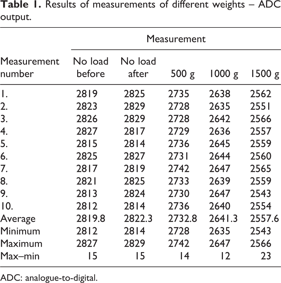
ADC: analogue-to-digital.
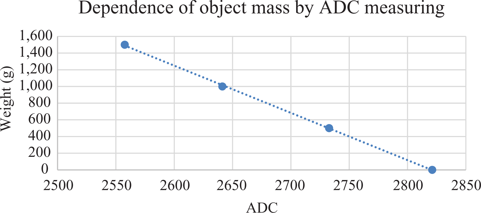
From the measured values (Table 2), basic statistical characteristics were prepared from which the stability of measurement (in grams) is not yet seen; therefore, a trend line was created in EXCEL and equation (1) was generated for converting the data into weight in grams (Figure 10).
Results of measurements of different weights in grams.

The creation of the formula for converting measured data to weight in grams.

where R 2 represents the reliability of the trend line.
The vertical axis represents the weight in grams and the horizontal axis is the number of ADC. On converting the measurements to weight, we get:

The expanded measurement uncertainty value is 3xSx 9 to which the scope with 99.7% probability fails the actual value.
We tried to do a repeat evaluation using the average values of the lowest numbers of the samples in interval 24–28 and the lower neighbour number, therefore, obtaining Table 3.
Measurement results of various weight – averaged ADC output.

ADC: analogue-to-digital.
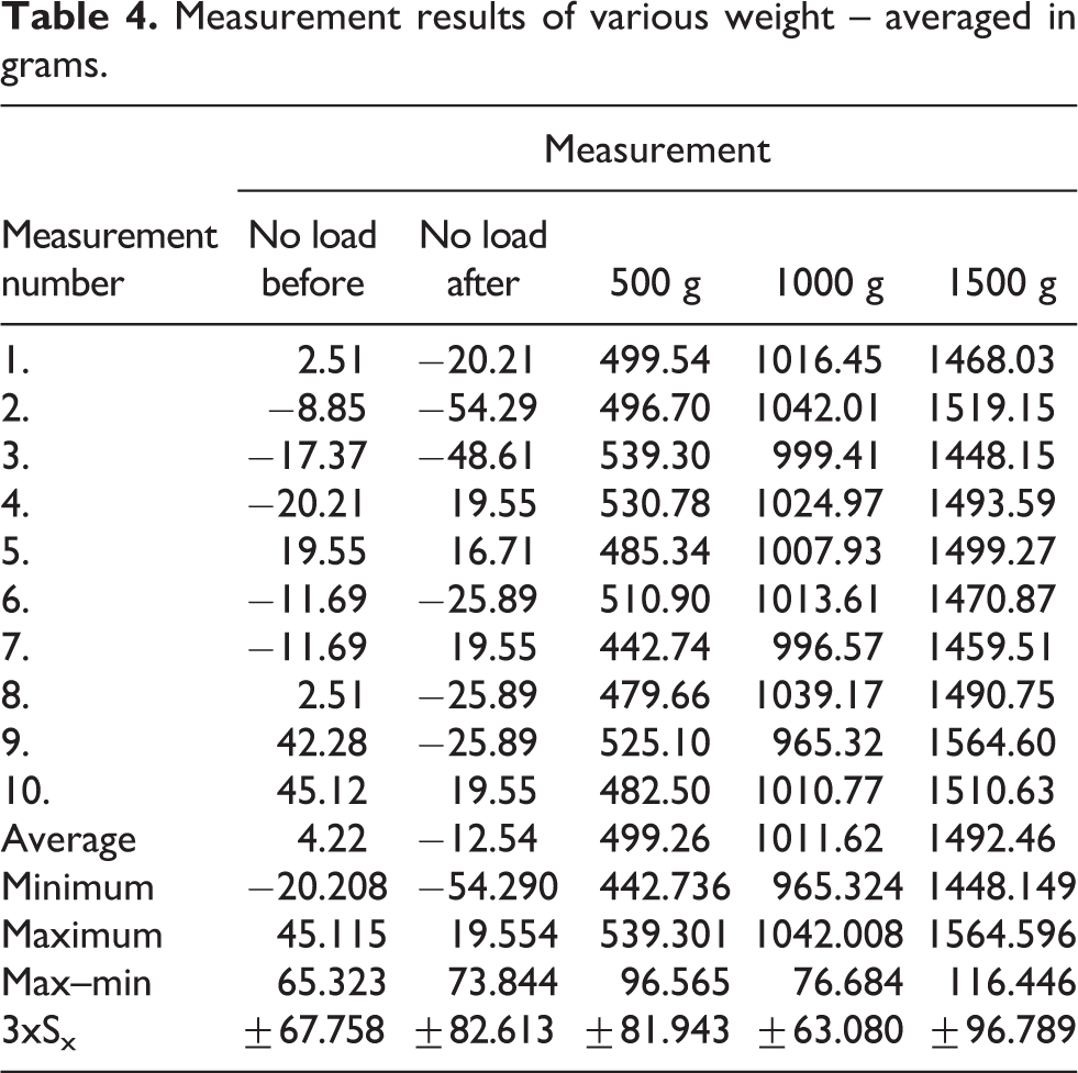
At first sight, the stability has deteriorated since max–min interval is slightly extended, but after converting to weight using the formula:

and subsequent evaluation of Table 4, the trend is a greater stability and lower extended measurement uncertain of measurement.
Measurement results of various weight – averaged in grams.
Conclusions
The sensitivity of the sensor (2% F.S. = 2 kg) and its error are greater than the results achieved; it is considered that the proposed measurement is possible to perform and does not overpass, by the manufacturer defined error of measurement, which also counts the error of nonlinearities (0.2%). It is also necessary to consider the error hysteresis (0.2%), which also affects the total error. The highest uncertainty of measurement in the case of the inclusion of only one sample is ±110.721 g, which in used conditions is a relatively good result. After averaging the two samples, the result in even more stable and highest measurement uncertainty was ±96.789 g.
In conclusion, it may be possible to perform the measurement of weight without changing the cycle of activity; however, the deterioration of the measurement errors compared to the static measurement of the robot by the same sensor can be visible. In our case, the most stable measurement is achieved in the time of rapid acceleration of the movement of the robot upwards (+). However, this change was not performed in full parallelism in our algorithm with the axis ‘z’. If it is possible to find in the trajectory of the robot the place with the perpendicular acceleration towards the axis ‘z+’, it will be little more a stable measurement. It is also necessary to set the size of sensor, so that in the sensor is not overloaded (130% F.S.). Due to the sensitivity of the measurement, it is possible to do a better choice because of the available undersized sensor 1 kN. A 50 N should be appropriate, regarding the maximum acceleration 2 m/s2.
In the future, we also propose to change the sampling time to 2, 5 ms, where it would be possible to get more samples averaged (at least three) to achieve lower random error of measurement. Also, it would be appropriate to use the evaluation unit with a higher frequency than the processing used (400 Hz), which would make it possible to enhance the time of sampling. Sampling would be useful to synchronize automatically with the robot. After the removal of these deficiencies, it will be necessary to verify raised hypothesis on a sufficient number of measurements (minimum of 30), in order to determine the measurement uncertainty of weight in this manner for a particular robot and its movement in space. 2,10
Footnotes
Declaration of conflicting interests
The author(s) declared no potential conflicts of interest with respect to the research, authorship and/or publication of this article.
Funding
The author(s) disclosed receipt of the following financial support for the research, authorship and/or publication of this article: This article is the result of the Project implementation: University Science Park TECHNICOM for Innovation Applications Supported by Knowledge Technology, ITMS: 26220220182, supported by the Research & Development Operational Programme funded by the ERDF.