
Abstract
This article presents the compliance modeling method of flexure-based mechanisms. The relationship between deformations and loads of the flexure members and the end effector is analyzed according to the zero virtual work principle. Using the matrix method, concise compliance equations for flexure serial and parallel structures are derived in conjunction with consideration of the compliance calculation errors of flexure hinges. Finally, relationships between the output compliances and geometrical parameters of a 3-revolute-revolute-revolute micro-motion stage are discussed. To validate the proposed compliance modeling method, the output compliances calculated by the empirical and theoretical compliance equations are subsequently compared with values derived from finite element analysis (FEA). The comparisons indicate that the results obtained from the empirical compliance equations are in good agreement with those derived from FEA, whereas the errors calculated by the theoretical equations are much larger, which demonstrate the accuracy of the empirical compliance equations and validate the proposed compliance modeling method.
Introduction
Flexure-based mechanisms, which can provide smooth motions through deflections of flexure hinges, are capable of achieving highly precise positioning with nanometer resolution. 1,2 In addition, these mechanisms have further advantages such as no friction losses, no need for lubrication, no hysteresis, ease of fabrication, compactness, and suitability for use in small-scale applications. 3 –6 Due to these advantages, coupled with nanometer positioning accuracy, they have been widely used in many industrial applications such as fiber optic coupling, micro-grippers, 7,8 scanning probe microscopy, 9,10 lithography, 11 micro/nano actuators, 12,13 micromachining, and semiconductor production.
Compliance is the crucial parameter that represents the relationship between an applied load and the deflection that occurs due to the load. Reasonable compliance modeling can reduce modeling errors and provide theoretical support for the design and optimization of flexure-based mechanisms, which will facilitate highly precise motion control. In general, flexure-based mechanisms can be divided into two types: planar mechanisms and space mechanisms. This work’s focus is on planar flexure-based mechanisms which have been applied most widely. These planar mechanisms possess monolithically machined structure and can achieve precise motion control. They could be processed as a whole on a piece of certain materials with wire cutting technology. In addition, they are usually composed of single-axis flexure hinges such as circular, corner-filled, and constant rectangular cross-section flexure hinge, which perform a two-dimensional motion. These flexure hinges are easy to design and manufacture.
There have been many methods adopted to derive the compliance modeling of flexure-based mechanisms 14 –17 including the pseudo rigid body (PRB) method, Castigliano’s second theorem, finite element analysis (FEA), and the matrix method. Li 18 designed a piezo-actuated XY stage with an integrated parallel, decoupled, and kinematics structure for micro- and nano-positioning applications. The compliance modeling was obtained from the PRB method to analyze mechanical performances such as kinematics, statics, stiffness, load capacity, and dynamics. Experimental results revealed that the micro-positioning system could achieve submicrometer accuracy for single-axis motion tracking, which validated the effectiveness of the proposed mechanism. Lobontiu et al. 19,20 derived closed-form equations for the compliances of corner-filleted flexure hinges using Castigliano’s second theorem. Corner-filleted flexure hinges behaved in a manner similar to elliptical flexure hinges and ranged within the domain confined by right circular flexure hinges and leaf flexure hinges in terms of compliance. Results derived from FEA and experimental results confirmed the model predictions. Qin 21 introduced a monolithic mechanism with two degrees of freedom. A computational optimization of the design based on FEA was performed. The compliance/stiffness of the mechanism, the decoupling capability of the leaf parallelograms, and the stress distribution at the lever mechanism were subsequently derived to optimize the design further. Meng 22 derived the stiffness/compliance modeling for corner-filleted flexure hinges based on FEA. The proposed modeling was found to be capable of enlarging the range of the ratio of thickness to length. Li 23 designed an XY parallel micro-positioning platform. The compliance modeling was established based on the matrix method, and it was subsequently verified by FEA. Lobontiu 24 proposed a matrix method to model the direct and inverse quasi-static response of constrained and over-constrained planar serial mechanisms. These mechanisms were composed of flexure hinges under bending, axial, and shear planar loading and small deformations. The proposed method employed a basic three-point compliance matrix corresponding to a single rigid link and a single adjacent flexure hinge that were subjected to a single point load. A displacement amplification planar device was studied to generate a model whose predictions were confirmed by FEA.
In the past decades, various compliance modeling methods have been developed. Nevertheless, these compliance modeling can rarely represent the relationship between compliance errors and geometrical parameters. Therefore, the present study addresses the compliance modeling method of planar flexure-based mechanisms. The compliance modeling is derived under conditions where the compliance calculation errors of the flexure hinges are taken into account. To validate the proposed compliance modeling method, FEA for a 3-RRR (revolute-revolute-revolute) flexure-based micro-motion stage is subsequently conducted.
The remaining sections of this article are organized as follows. In the section “Compliance/stiffness modeling,” the compliance modeling method of planar flexure-based mechanisms is derived based on the matrix method, including flexure serial and parallel structures. The calculation errors of flexure hinges are considered in the propose modeling method. In the section “Compliance of the constant rectangular cross-section flexure hinge,” to calculate the compliance of the micro-motion stage, the theoretical and empirical compliance equations of the constant rectangular cross-section flexure hinge are presented. In the section “Application to 3-RRR micro-motion stage,” compliance modeling of a 3-RRR micro-motion stage is obtained based on the proposed modeling method, and the relationships between output compliances and geometrical parameters are discussed. The output compliances calculated by the empirical and theoretical compliance equations are subsequently compared with those derived from FEA. Finally, conclusions are drawn in the section “Conclusions.”
Compliance/stiffness modeling
For the flexure-based mechanism, the kinematic structure has large effect on its performance. According to the kinematic structure, flexure-based mechanisms can be divided into two categories: the flexure serial structure and the flexure parallel structure. Most existing serial structures adopt a stacked or nested structure with one degree of freedom, and thus they are easier to design. By contrast, the parallel structures possessing the closed-loop kinematic features have good performance, such as high rigidity, high load carrying capacity, and high accuracy. 25 –27
Flexure serial structure
As for a flexure serial structure, the errors will accumulate along the kinematic chain. Accordingly, it is necessary to analyze the compliance modeling method in terms of the modeling error. As shown in Figure 1, a flexure serial structure is comprised of several rigid beams and notch flexure hinges. Considering the deformation errors, the relationship between the elastic deformation of a flexure member and the total deformation at the free end of the flexure serial structure can be obtained based on matrix method,
24,25
and it can be expressed as Flexure serial structure.

Based on the zero virtual work principle, the relationship between the external force at the free end and the reaction force at a flexure member can be expressed as

where
Then, the accumulation of both rotational and translational deformations at the free end of the flexure serial structure can be obtained as

where
Considering the modeling error

where
Thus, the total compliance and compliance error of the flexure serial structure can be given as, respectively


Flexure parallel structure
Considering the advantages of the flexure parallel structure, parallel mechanisms are preferable than serial ones. They have been adopted in many micro-motion stages, and they can achieve a uniform performance inside the workspace and possess decoupled performance. As shown in Figure 2, the flexure parallel structure is composed of several limbs and a rigid platform. Flexure parallel structure.

The force and moment

where
Considering the modeling errors

where
Thus, the total stiffness and stiffness errors of the flexure parallel structure can be given as, respectively


Obviously, the compliance modeling shows that the compliance error relies on the precision of the flexure hinge and the geometrical parameters of the flexure-based mechanisms.
Compliance of the constant rectangular cross-section flexure hinge
The compliances of planar flexure-based mechanisms can be obtained from the proposed modeling method discussed above, and thus the compliance of the flexure hinge is crucial. To derive the compliance modeling of flexure-based mechanisms, the compliance of flexure hinge should be analyzed first. Without loss of generality, the constant rectangular cross-section flexure hinge is selected because it is widely used in the planar flexure-based mechanisms and simple to design and manufacture.
The accuracy of a flexure-based mechanism relies on the precision of the flexure hinge model. Therefore, compliance equations of flexure hinges must be as accurate as possible to minimize the overall modeling error of flexure-based mechanisms by reducing the accumulated modeling errors of the hinges.
Notch flexure hinges are produced by drilling or milling two closely spaced holes, forming a constant rectangular cross-section cutout. 28,29 The geometrical parameters of the constant rectangular cross-section flexure hinge are illustrated in Figure 3. It includes the hinge length L, the hinge thickness t, the side height h, the rigid beam width W, the total height H, and the total depth D.

Geometrical dimensions of a constant rectangular cross-section flexure hinge.
The in-plane compliance matrix of the constant rectangular cross-section flexure hinge can be expressed as

where
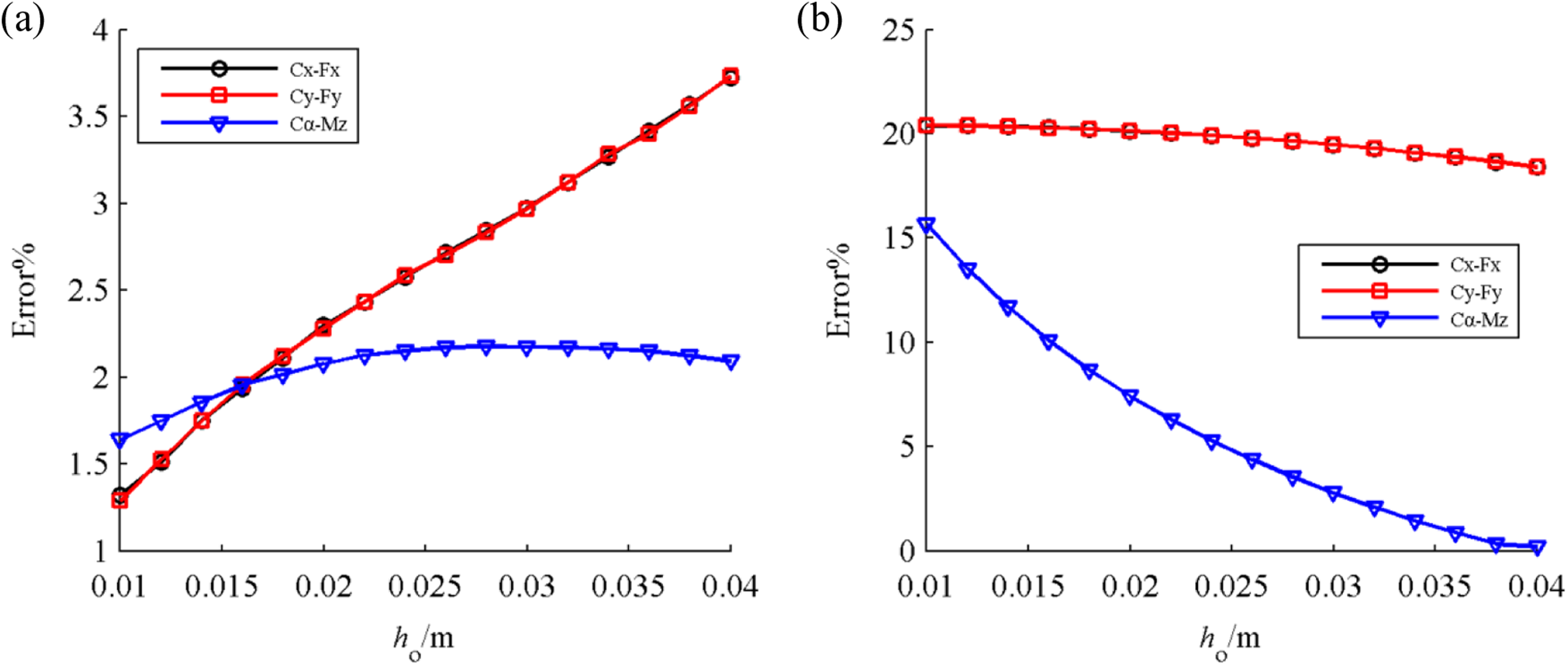
The most commonly employed theoretical compliance equations of


where E is Young’s modulus.
Equations (13 –17) could be the theoretical compliance equations. 29 In addition, the stress concentration has a substantial influence on the axial compliance calculation. The exponential relationship between geometrical parameters and deformations can be derived through FEA. In an earlier article, 30 we have obtained the empirical compliance equations based on the exponential model, and they can be expressed as


where α is the shear coefficient.
Application to 3-RRR micro-motion stage
The parallel configuration of the 3-RRR structure is advantageous over a serial configuration structure. In addition, the 3-RRR structure is a common and typical parallel structure. Numbers researches have been carried on the 3-RRR micro-motion stage. Therefore, to validate the proposed compliance modeling of flexure-based mechanisms obtained in the section “Compliance/stiffness modeling,” the output compliances of RRR and 3-RRR stages are derived. 31 As shown in Figure 4, the RRR compliant structure is comprised of three flexure hinges, and the 3-RRR micro-motion stage consists of three RRR limbs.

3-RRR flexure-based micro-motion stage. 3-RRR: 3-revolute-revolute-revolute.
Output compliance modeling of the 3-RRR micro-motion stage
Note that all flexure hinges are modeled to have three degrees of freedom (3-DOF; i.e. bending compliance about the z-axis and axial and shear compliances along the x and y axes, respectively). Flexure hinges are connected into a 3-DOF planar compliant micro-motion stage. The proposed RRR compliant limb is illustrated in Figure 5.

RRR flexure-based mechanism: (a) applied forces/moments at output point o 1; (b) applied forces/moments at output point o. 3-revolute-revolute-revolute.
The compliances at point o 1 (Figure 5(a)) are first calculated. The overall compliances of the RRR flexure-based stage at point o (Figure 5(b)) are then obtained by summing all the contributions to the compliances in the corresponding directions of each individual flexure hinge. Considering bo and ho are the key distances of the RRR stage, the output compliance matrix at o 1 can be expressed as

where
When the output forces are applied to point o rather than o
1, and the displacements at this point are desired, the transformation matrix

where
The 3-RRR flexure-based micro-motion stage is composed of three RRR limbs which are arranged 120° apart (i.e. 2π/3 rad), as shown in Figure 4. According to the modeling method described above, the output compliance matrixes at point o of limbs 2 and 3, respectively, are


where
Then, the compliance matrix of the 3-RRR flexure-based micro-motion stage can be given as

Validation and analysis
The relationships between the main compliances (the axial compliance Cx-Fx , shear compliance Cy-Fy , and bending compliance Cα-Mz ) and the geometrical parameters of the 3-RRR micro-motion stage are first discussed. Considering the accuracy of FEA, it is used as a benchmark. 4,31 In addition, for the planar flexure-based mechanisms, the boundary conditions are simple and clear, and thus they can be obtained easily. Then, the main compliances calculated by the empirical compliance equations and theoretical compliance equations are compared with the values derived from FEA to examine the output compliance errors. All flexure hinges have equivalent geometrical parameters and material properties. The geometrical parameters and material properties of the RRR and 3-RRR flexure-based micro-motion stages are given as E = 210 GPa, ν = 0.30, ho = 30 mm, bo = 60 mm, h 1 = 30 mm, b 1 = 25 mm, L = 10 mm, h = 4 mm, t = 2 mm, W = 5 mm, and D = 10 mm.
A FEA model was generated using ANSYS Workbench, as shown in Figure 6. The results obtained from FEA are easily influenced by the mesh density and boundary conditions. Mesh types and mesh density could influence the simulation accuracy and simulation time step. In general, FEA model with hexahedral meshes can obtain high calculation accuracy than the one with tetrahedron meshes. To increase simulation accuracy, the FEA model with appropriate mesh density could be selected. For similar mesh quality, the model with high mesh density has smaller simulation time steps and more elements, and thus increases computational costs and calculation accuracy, respectively. Therefore, the hexahedral meshes and appropriate mesh density are selected in this work. In addition, surface A, surface B, and surface C are fixed, and the forces are applied to point o.

FEA model of a 3-RRR flexure-based micro-motion stage. FEA: finite element analysis; 3-RRR: 3-revolute-revolute-revolute.
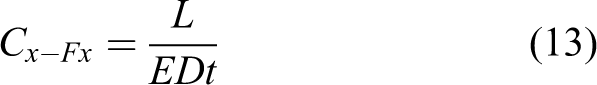
To validate the proposed compliance modeling method, the output compliances of 3-RRR micro-motions are derived by the empirical equations. Relationships between the main compliances obtained from the empirical equations and the geometrical parameters are depicted first, as follows. Figure 7 shows the relationships between the main compliances and the geometrical parameter bo . The curves of the axial compliance and shear compliance nearly coincide. Meanwhile, the axial compliance, shear compliance, and bending compliance all increase with increasing bo . The relationships between the main compliances and the geometrical parameter ho are shown in Figure 8. Similarly, the curves of the axial compliance and shear compliance again nearly coincide, and the main compliances all increase with increasing ho .

Relationships between the main compliances and the geometrical parameter bo : (a) the axial compliance and the shear compliance; (b) the bending compliance.
Relationships between the main compliances and the geometrical parameter ho : (a) the axial compliance and the shear compliance; (b) the bending compliance.
The relationships between the main compliances and the geometrical parameter h 1 are shown in Figure 9. It shows that the axial compliance and shear compliance are stable with increasing h 1, while the bending compliance decreases rapidly. In general, the analysis above indicates that the proposed compliance modeling can build relationships between compliances and geometrical parameters, which can facilitate the design and optimization of flexure-based mechanisms.

Relationships between the main compliances and the geometrical parameter h 1: (a) the axial compliance and the shear compliance; (b) the bending compliance.
In addition, the main compliances calculated by the theoretical compliance equations and FEA can be obtained with increasing geometrical parameter bo , ho , and h 1. Without loss of generality, only the relationships between these compliances and geometrical parameter bo are illustrated in Figure 10. As the results obtained from the empirical compliance equations in Figure 7(a), the curves of the axial compliance and shear compliance nearly coincide. The trend is similar to the values calculated by the empirical equations. Nevertheless, there is relative large difference between theoretical values and FEA values.

The main compliances calculated by theoretical compliance equations and FEA: (a) the axial compliance; (b) the shear compliance; (c) the bending compliance. FEA: finite element analysis.
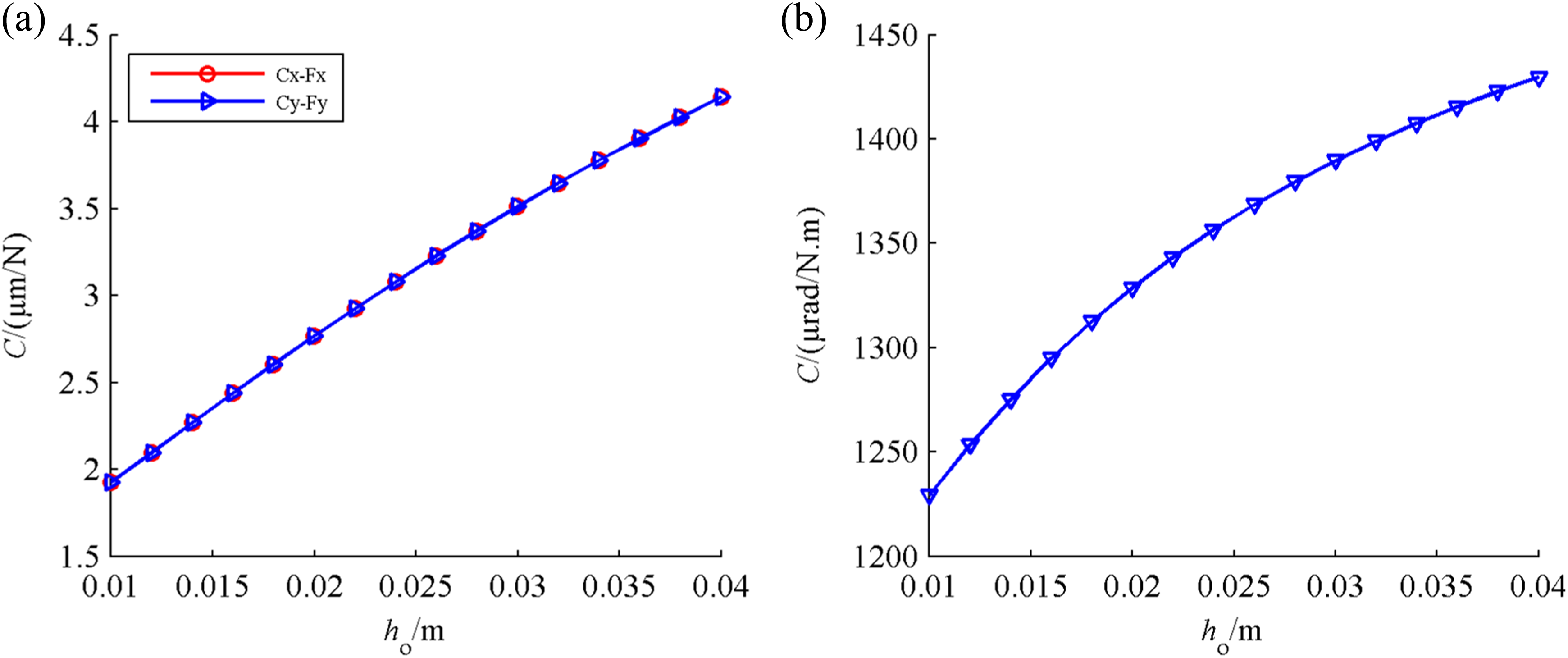
The main compliances calculated by the empirical and theoretical compliance equations are compared with those derived from FEA, as follows. As shown in Figure 11(a), the compliance calculation errors determined by the empirical equations of axial compliance, shear compliance, and bending compliance all decrease with increasing bo . In addition, the compliance calculation error of the axial compliance is similar to that of the shear compliance, and it is below 3%. In contrast, the compliance calculation errors determined by the theoretical equations are shown in Figure 11(b). We can see that the curves of the axial compliance calculation error and shear compliance calculation error coincide, and both of them exhibit a downward trend from 25% to around 18% with increasing bo . With an equivalent variation in bo , the bending compliance error exhibits a decrease from 7% to about 0% and then an increase to about 13%. Hence, the analysis shows that the compliance errors calculated by the theoretical equations are much larger than those calculated by the empirical equations.
Compliance calculation errors: (a) calculated by the empirical compliance equations; (b) calculated by the theoretical compliance equations.
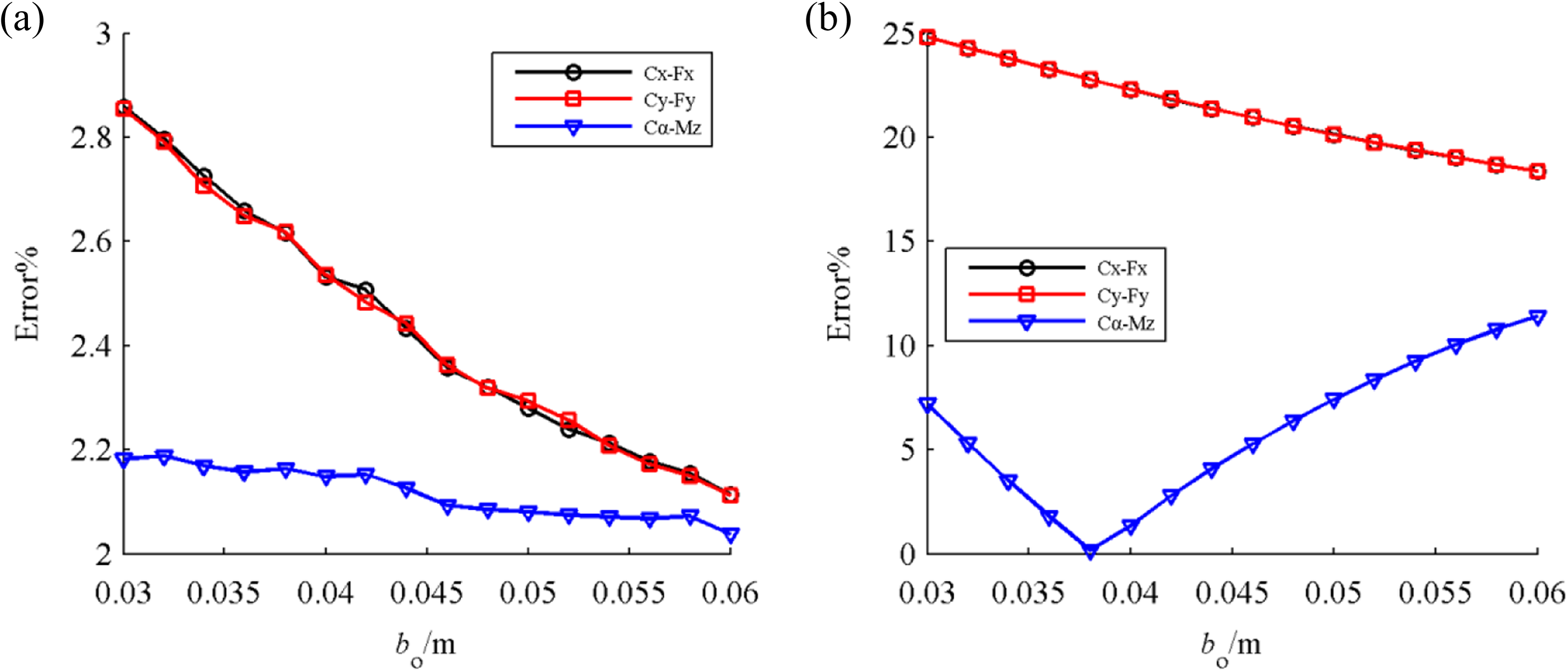
As can be seen from Figure 12(a), the compliance calculation errors determined by the empirical equations for the axial compliance, shear compliance, and bending compliance all increase with increasing ho . In addition, the compliance calculation error of the axial compliance is similar to that of the shear compliance, and it is below 4%. In contrast, the compliance calculation errors determined by the theoretical equations are shown in Figure 12(b). It shows that the curves of the axial compliance calculation error and shear compliance calculation error coincide, and both of them remain stable at around 20%, while the bending compliance error experiences a decrease from 16% to about 0 with increasing ho .
Compliance calculation errors: (a) calculated by the empirical compliance equations; (b) calculated by the theoretical compliance equations.
According to Figure 13(a), with increasing h 1, the compliance calculation errors of the axial compliance and shear compliance fluctuate between 2.25% and 2.35%, while the compliance error of the bending compliance exhibits an upward trend from 2% to 2.3%. In contrast, the compliance calculation errors determined by the theoretical equations are shown in Figure 13(b). It shows that the curves of the axial compliance calculation error and shear compliance calculation error coincide, and both of them stabilize at 20%, while the bending compliance error exhibits a decrease from 15% to about 1%, and then an increase to about 8% with increasing h 1.

Compliance calculation errors: (a) calculated by the empirical compliance equations; (b) calculated by the theoretical compliance equations.
Altogether, with increasing ho , bo , and h 1, the compliance errors calculated by the empirical equations are below 4%, while the compliance errors determined by the theoretical equations are about 20%. Therefore, the compliance calculation errors determined by the empirical equations are much smaller than those calculated by the theoretical equations, which validates the proposed compliance modeling method and the accuracy of the empirical compliance equations. Simultaneously, the proposed compliance modeling method can be employed to build relationships between compliance errors and geometrical parameters, which can assist designers with selecting optimal geometrical parameters to satisfy the expected compliances and minimum compliance errors.
Conclusions
In this article, compliance modeling method of planar serial and parallel flexure-based mechanisms was derived in terms of the compliance calculation errors of flexure hinges. Relationships between the output compliances and the geometrical parameters of a 3-RRR micro-motion stage were discussed, and the output compliances were calculated by empirical compliance equations, theoretical compliance equations, and subjected to FEA to validate the proposed method. Based upon the results obtained, we can draw the following conclusions.
Compliance modeling of serial flexure-based mechanisms can be obtained from the accumulated deformations of flexure hinges, while compliance modeling of parallel mechanisms can be derived from the accumulated forces and moments of limbs. It shows that the compliance error relies on the precision of the flexure hinge and the geometrical parameters of the mechanism.
The proposed compliance modeling method can be used to build relationships between compliances and geometrical parameters, and it can represent relationships between compliance errors and geometrical parameters, which facilitate the selection of optimal geometrical parameters.
Comparisons with the results obtained from FEA demonstrate that the proposed compliance modeling of the 3-RRR micro-motion stage is valid, and the empirical compliance equations (compliance errors are below 4%) are more accurate than the theoretical compliance equations (compliance errors are about 20%).
Footnotes
Declaration of conflicting interests
The author(s) declared no potential conflicts of interest with respect to the research, authorship, and/or publication of this article.
Funding
The author(s) disclosed receipt of the following financial support for the research, authorship, and/or publication of this article: This work was supported by the National Basic Research Program of China (Grant No. 2011CB302400), the National Science Foundation of China (Grant No.51275260), and the National Science and Technology Major Project of China (Grant No. 2015ZX04014021 and Grant No.2015ZX04001002).