
Abstract
In this article, a novel decoupled two-degree-of-freedom parallel flexural mechanism is proposed for precision engineering, such as micro/nanomeasuring and machining. The two-degree-of-freedom flexural mechanism is developed with the parallel-kinematic constraint map method to achieve totally geometric decoupling and the actuator isolation. By means of the matrix which is based on compliance modeling method, the compliance matrix of the flexural mechanism has been analytically derived and then the obtained theoretical results are verified by the finite element analysis. Experiment tests are conducted to investigate the practical performances of the developed two-degree-of-freedom flexural mechanism. The experimental results show that the maximum stroke along z-axis and y-stroke are 10.82 and 11.84 µm, respectively, and the corresponding maximum couplings in y-axis and z-axis directions are less than 3%. The first obtained resonant frequencies in the two moving directions are 420 and 450 Hz through the method of swept excitations, respectively.
Keywords
Introduction
Nowadays, flexural mechanisms with ultrahigh precision play more and more important roles in the fields of micromanipulation systems,1,2 micro/nanoposition systems,3–5 advanced manufacture, 6 measurement, 7 and so on. 8 Specifically, two-degree-of-freedom (2-DOF) flexural mechanisms are mainly employed in the non-resonant elliptical vibration cutting (EVC) mechanisms, 2-DOF fast tool servo (FTS), 2-DOF micro/nanopositioning stages for measurement, 9 and so on. In view of the mentioned significant applications, many researchers are devoted a large number of efforts to improve the working performances of 2-DOF flexural mechanisms, for instance, increasing the motion stroke, widening the working bandwidth, and eliminating the motion couplings.
The practical applications of 2-DOF flexural mechanisms are often seriously restricted by the coupling between the two motion axes, which ultimately lead to the undesired parasitic errors. Hence, the two motion axes must be sufficiently decoupled from each other so that a motion in one axes does not affect the other one. 10 However, almost all of the reported non-resonant EVC mechanisms11–14 have strong coupling motions and parasitic rotations, which greatly constraint the applications in other fields such as micro/nanopositioning. As for most developed XY position stages,4–7 which can decouple motions with methods of adopting the double-symmetric structures or the serial configuration, nonetheless, both the double-symmetric structures and serial configuration will definitely block further decrease in structure sizes and limit widening of the working bandwidth as a result of increasing moving inertia. Besides, Polit and Dong 6 developed a parallel XY position stage with high working bandwidth for micro/nanomachining, which adopts asymmetric structure and hybrid compliant-notch parallelogram mechanism to eliminate the inherent parasitic motion, but the decoupling performance highly depended on the optimization of dimensional parameters, and it was not a universal method for achieving accurate motions. Similarly, most of developed 2-DOF FTSs are also greatly restricted by the high coupling and low bandwidth. For example, Liu et al. 15 developed a long stroke FTS which was actuated by voice coil motors and piezoelectric actuators (PEAs), but the applications of voice coil motors and the serial configuration of PEAs greatly restrict the working bandwidth.
Considering all these aforementioned factors, the following design criteria should be critically guaranteed: (1) employing parallel configuration to obtain compact structure and high working bandwidth and (2) geometrically decoupled motions of the input and output end. Based on the widely potential applications of the 2-DOF flexural mechanisms, a novel piezoelectrically actuated 2-DOF flexural mechanism with totally decoupled motions will be proposed in this article. In section “Design of the 2-DOF flexural mechanism,” the 2-DOF decoupled flexural mechanism is designed with the parallel-kinematic constraint map (PKCM) method. Moreover, the kinematic model of 2-DOF flexural mechanism is built and investigated by both analytical analysis and finite element analysis (FEA) in section “Modeling and analysis of the 2-DOF flexural mechanism”; the dynamic performance of the flexural mechanism is also investigated by FEA in this section. In section “Performances testing of the 2-DOF flexural mechanism,” experimental tests on the prototype are conducted to investigate practical performances of the flexural mechanism. Finally, the main conclusions of this article are summarized.
Design of the 2-DOF flexural mechanism
In order to design a geometrically decoupling parallel-kinematic XYZ position stage, Awtar et al. 16 first presented a PKCM method, which can overcome the coupling and overconstraint among different motion axes. In this section, a similar method, which only adopts two-dimensional (2D) PKCM method in the YZ plane, is employed to aid design a parallel-kinetic YZ flexural mechanism. The designed 2D constraint map is shown in Figure 1, which comprises two kinds of building blocks—rigid stages represented by the blocks and constraint elements represented by colored connectors. The rigid stages are labeled as Ground, Y stage, Z stage, and YZ stage, the nomenclature in terms of the primary mobility of any given stage, for example, the Y stage and Z stage are seriously constrained so that the mentioned stages have mobility only along the Y and Z directions, respectively. Similarly, the YZ stage is greatly constrained such that it has movements only along the Y and Z directions.
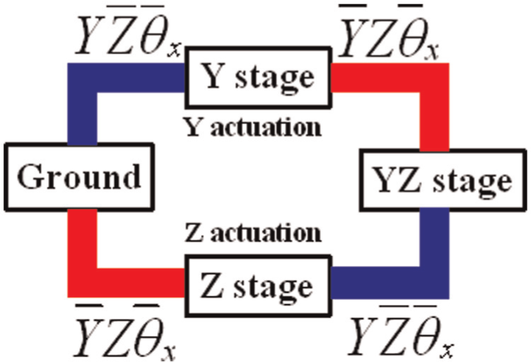
Proposed constraint map for parallel-kinematic YZ flexural mechanism synthesis.
As shown in Figure 1, the constraint elements are colored blue and red. The blue constraint elements allow motion only in the Y direction and constrain all other motions (
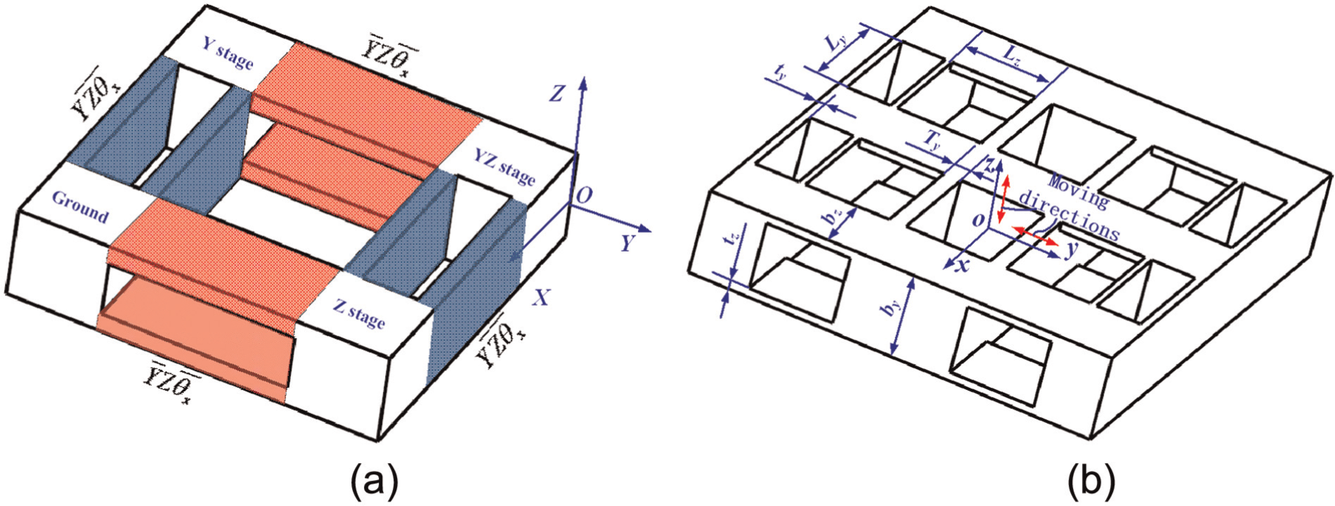
Flexural mechanism based on constraint map: (a) initial structure of flexural mechanism and (b) final structure of flexural mechanism.
As shown in Figure 2(a), the physical rigid stages are all colored white, and the PFMs, which are corresponding to the Y and Z directions constraint elements in Figure 1, are colored blue and red, respectively. In order to eliminate parasitic motion in the X direction during Y actuation process and parasitic rotation around the Y axis during Z axis actuated process, the flexural mechanism employs bi-symmetric structure with respect to the X and Y axes, respectively. Ultimately, the evolved physical embodiment is generated and shown in Figure 2(b). Then, installations of the PEAs and capacitive sensors are taken into consideration, and final structure of the proposed flexural mechanism is designed as shown in Figure 3. Besides, two sensors are orthogonally mounted on the base, which are employed to obtain the displacements of output end.
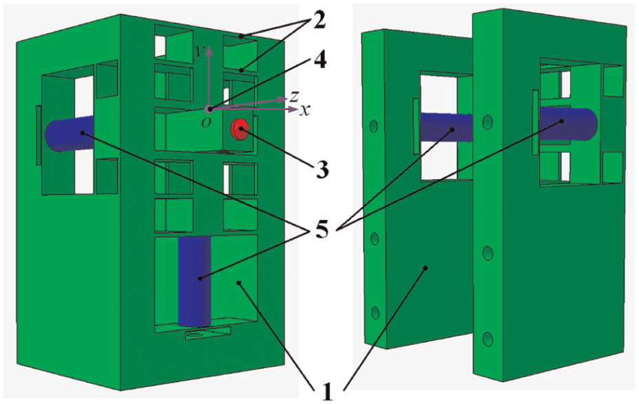
Schematic of the designed 2-DOF flexural mechanism (1: the base, 2: the flexure hinges, 3: the output end, 4: the Cartesian coordinates frame, and 5: the piezoelectric actuators).
Modeling and analysis of the 2-DOF flexural mechanism
Static modeling
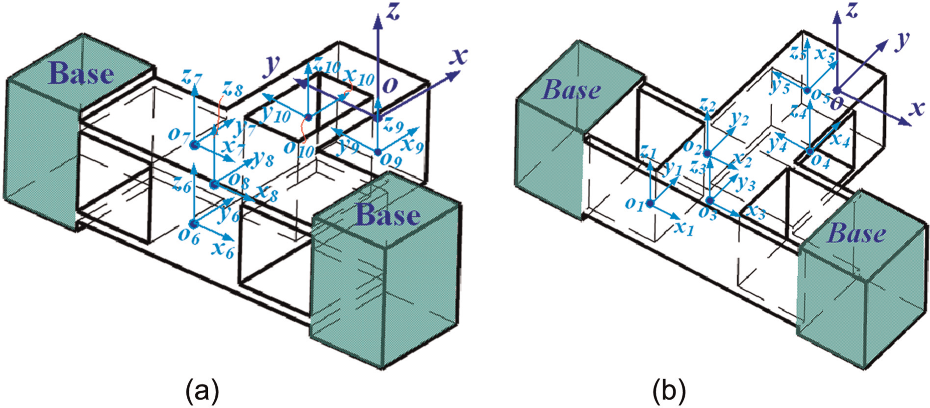
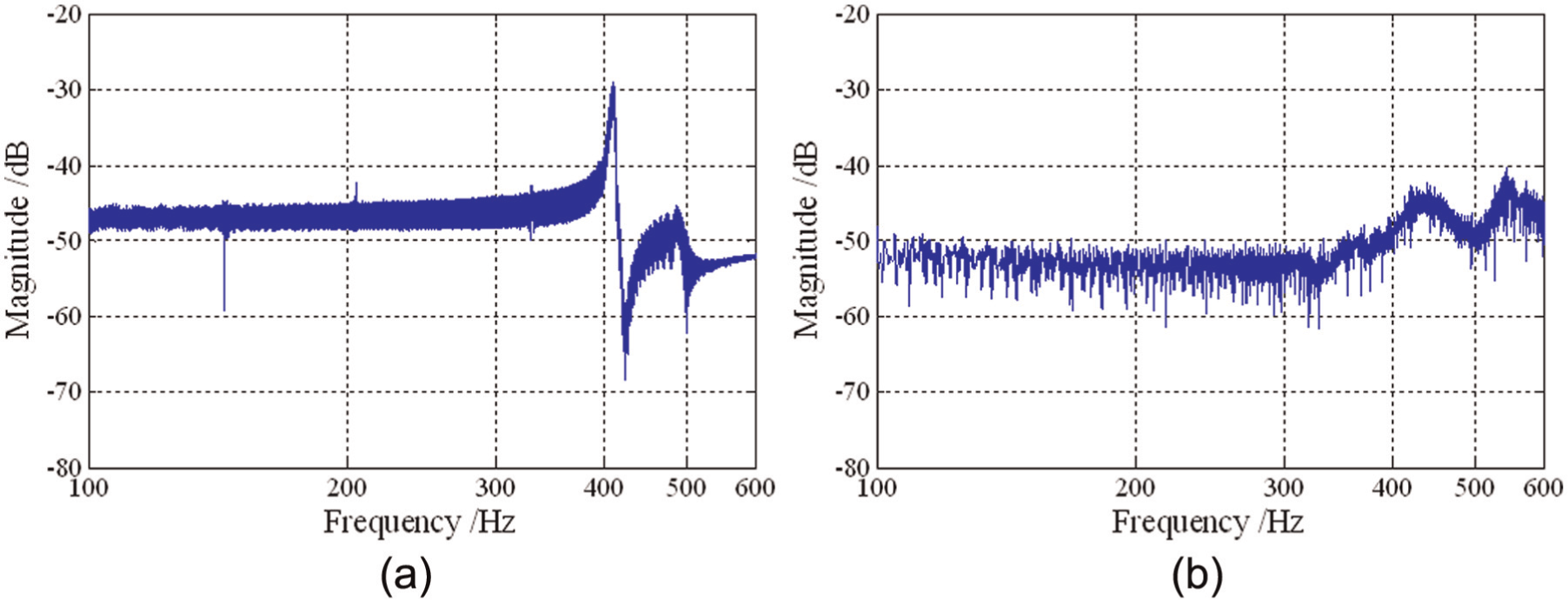
In order to simplify the modeling process, a simplified planar schematic diagram is shown in Figure 4(a), which is the front view of the 2-DOF flexural mechanism. Then, the corresponding equivalent spring model is illustrated in Figure 4(b), in which each flexure hinge, which is marked by local coordinate frame, is regarded as an equivalent spring. With the purpose to understand basic attributes of the flexural mechanisms, the properties including the input compliance and the output compliance are modeled and analyzed by the matrix-based compliance modeling (MCM) method. In this article, the compliance models are built without taking factors of the PEAs and the contact conditions into account. To account for these factors, some necessary references17,18 can be available.
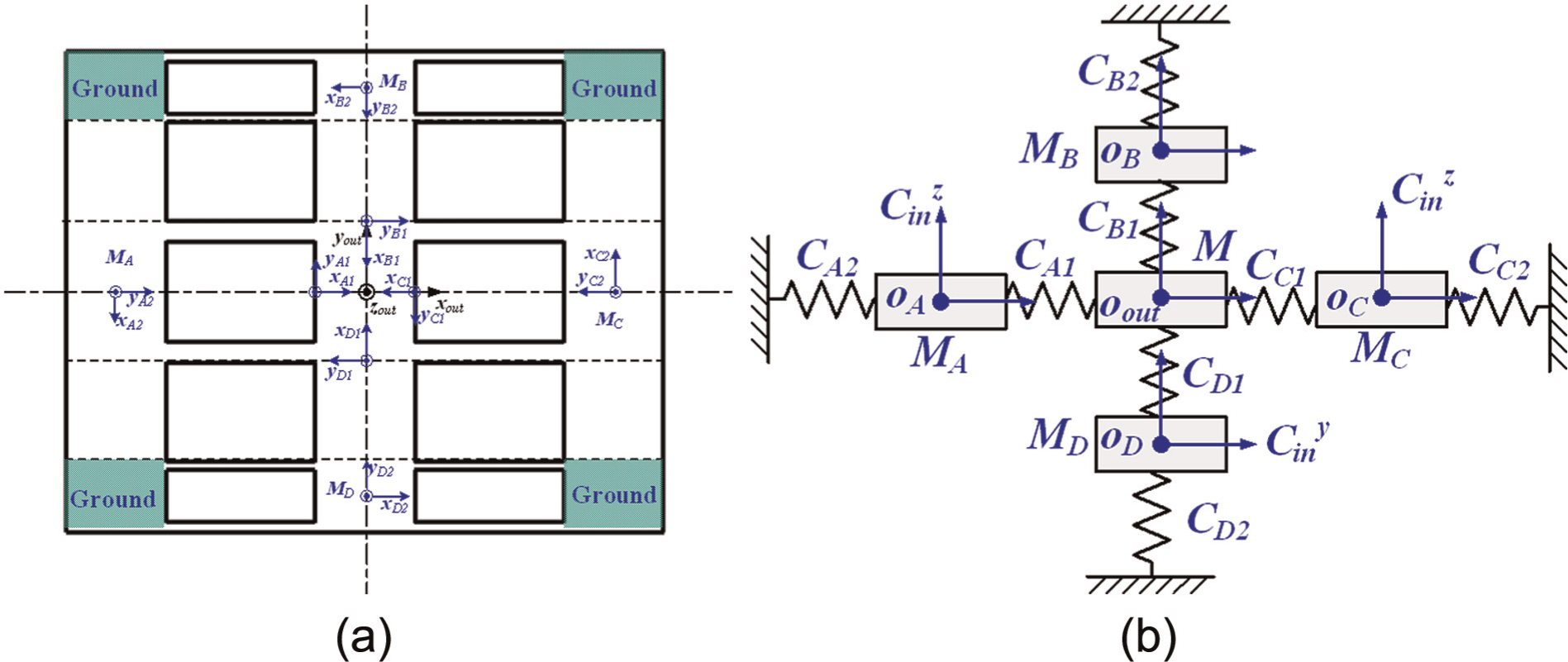
Schematic of the connection arms: (a) simplified schematic of the flexural mechanism and (b) equivalent spring model of the flexural mechanism.
Output compliance
As for the 2-DOF flexural mechanism, the output platform is constructed by parallel connections of four arms, which are named as arms A, B, C, and D, respectively, and the corresponding structure features and dimensional parameters are illustrated in Figure 2(b). Since arm A is symmetric with C with respect to the Y axes, and the arms B and D have similar character with respect to the X axis, the structure features of the arms A and B are only illustrated in Figure 5(a) and (b), respectively.
Schematic of the flexural mechanism: (a) arm A and (b) arm B.
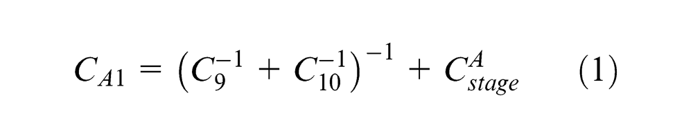
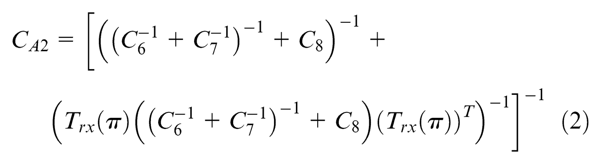
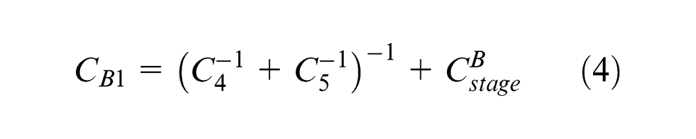
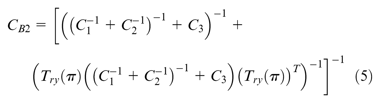
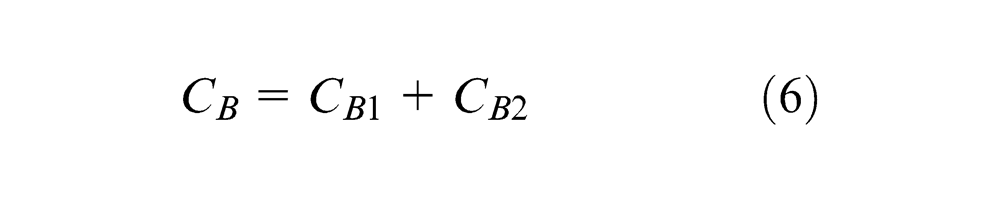
Here, the output compliance Cout is defined as the compliance of the point Oout . Based on the MCM method, the compliances of the arms A and B with respect to the point of output are shown in Figures 4 and 5, which can be expressed as follows
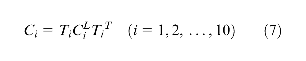
where Ti
represents the compliance transformation matrix (CTM) from local coordinate oi-xiyizi
of the ith leaf-type flexure hinge (LFH) to the global coordinate o-xyz;
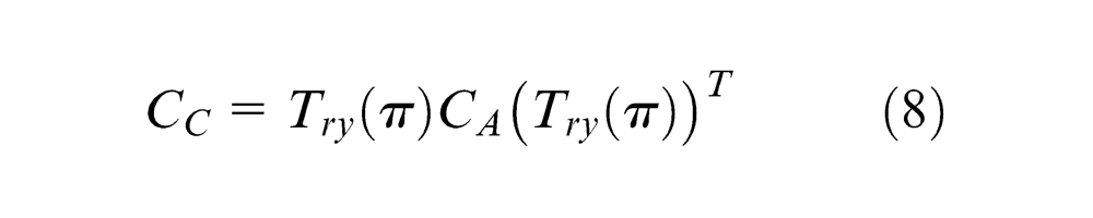
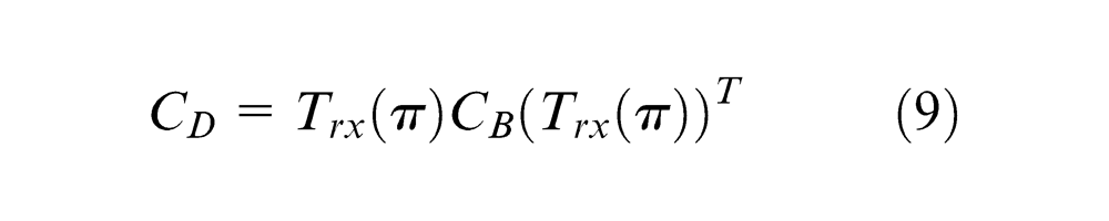
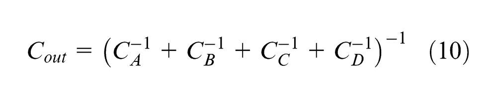
In view of the four connect arms are parallel, the output compliance of the whole mechanism can be obtained as follows
Input compliance
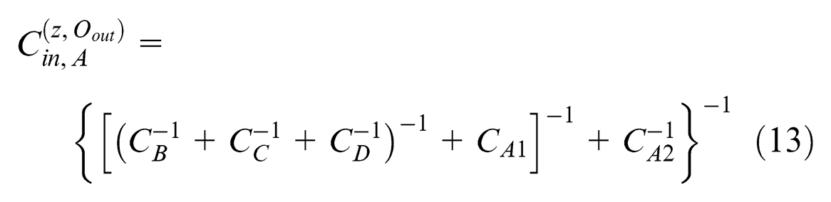
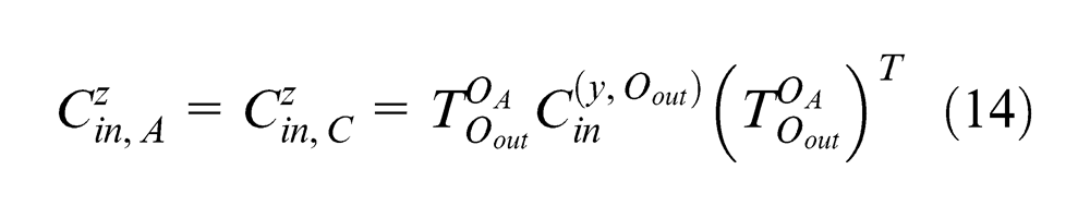
Considering the flexural mechanism is symmetric with respect to x-axis, the input compliance of point OD
in y-axis direction, which is named as
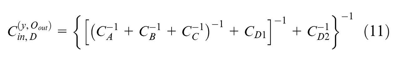
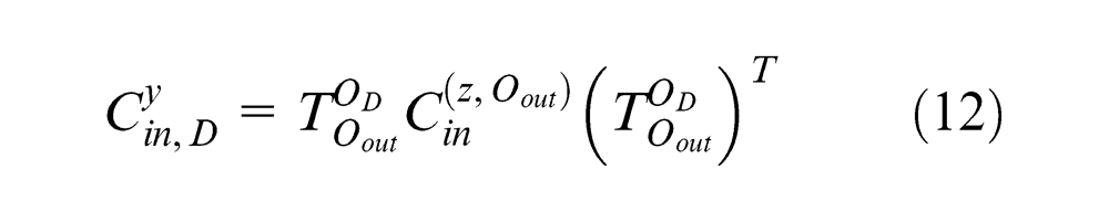
where
FEA of the mechanism
Statics investigation
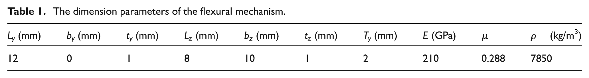
During the statics and dynamics verification process, the dimensional parameters of the 2-DOF flexural mechanism are chosen as shown in Table 1. To verify the output compliance obtained by the MCM method, external forces along the x-axis, y-axis, and z-axis are, respectively, applied on the point Oout to obtain the corresponding output compliance with the FEA method. The obtained compliances by theoretical analysis and FEA are shown in Table 2. As shown in Table 2, it can be observed that the deviation of the output compliance along the x-axis is about 0.4%, demonstrating the efficiency and accuracy of the theoretical model. However, deviations of the compliances along the y-axis and z-axis are 1.7% and 3.5%, respectively. The relatively large modeling error may be attributed by the ignorance of deformation behavior of output platform that is regarded as rigid body.
The dimension parameters of the flexural mechanism.
Result comparisons of the FEA and MCM method.
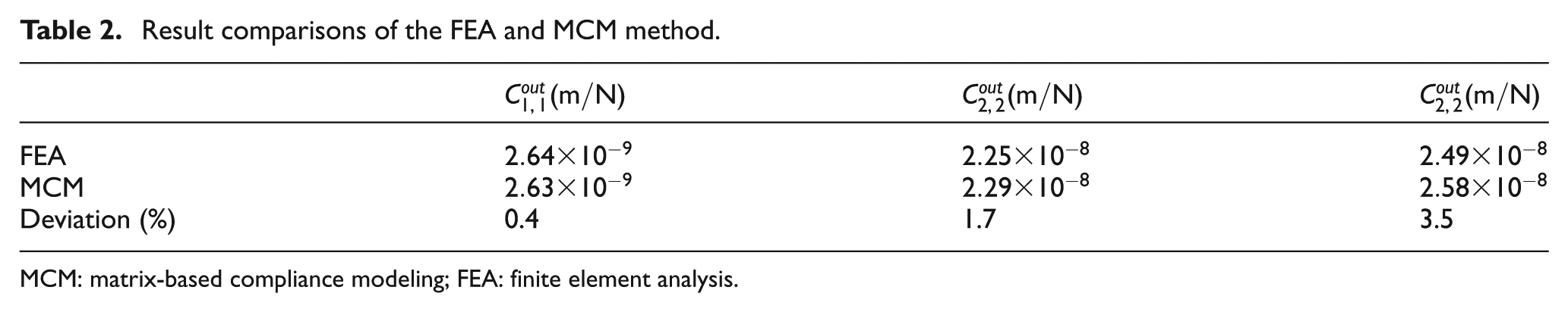
MCM: matrix-based compliance modeling; FEA: finite element analysis.
Considering the stiffness and stroke of the employed actuators (PI P-880.51 with kpzt = 100 N/µm and ds = 15 µm), and the preloading effects, the estimated maximum displacements of the input ends will be less than 14 µm.18,22,23 With the maximum deformation, the corresponding Von Misses stress distribution of the flexural mechanism is shown in Figure 6. It can be observed from the distribution diagram that the maximum stress is less than 125 MPa, which is well under the strength value of adopted material (65 Mn), so the long-term linearity and repeatability of the flexural mechanism can be guaranteed.
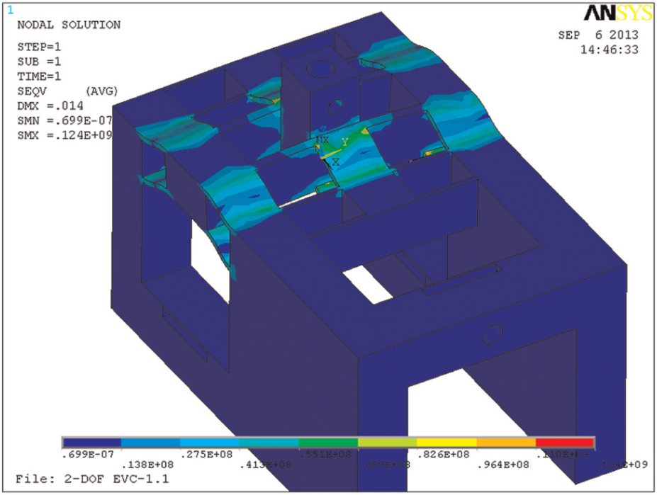
The equivalent stress distribution with maximum deformation.
Dynamics investigation
The FEA-based modal analysis is further conducted to test the dynamic performance of the 2-DOF flexural mechanism, and the first four vibrational mode shapes are shown in Figure 7. As shown in Figure 7, the two motions of the platform along the y-axis and z-axis occur in the first two modes, and the first two natural frequencies are 4441 and 4471 Hz, respectively. However, the undesired rotation and twist occur in the third and forth modes with the corresponding natural frequencies equaling 6474 and 8305 Hz, respectively. Fortunately, the third natural frequency is much higher than the first two frequencies. Thus, the first two modes are the most prominent modes and will dominate all other higher frequency modes.
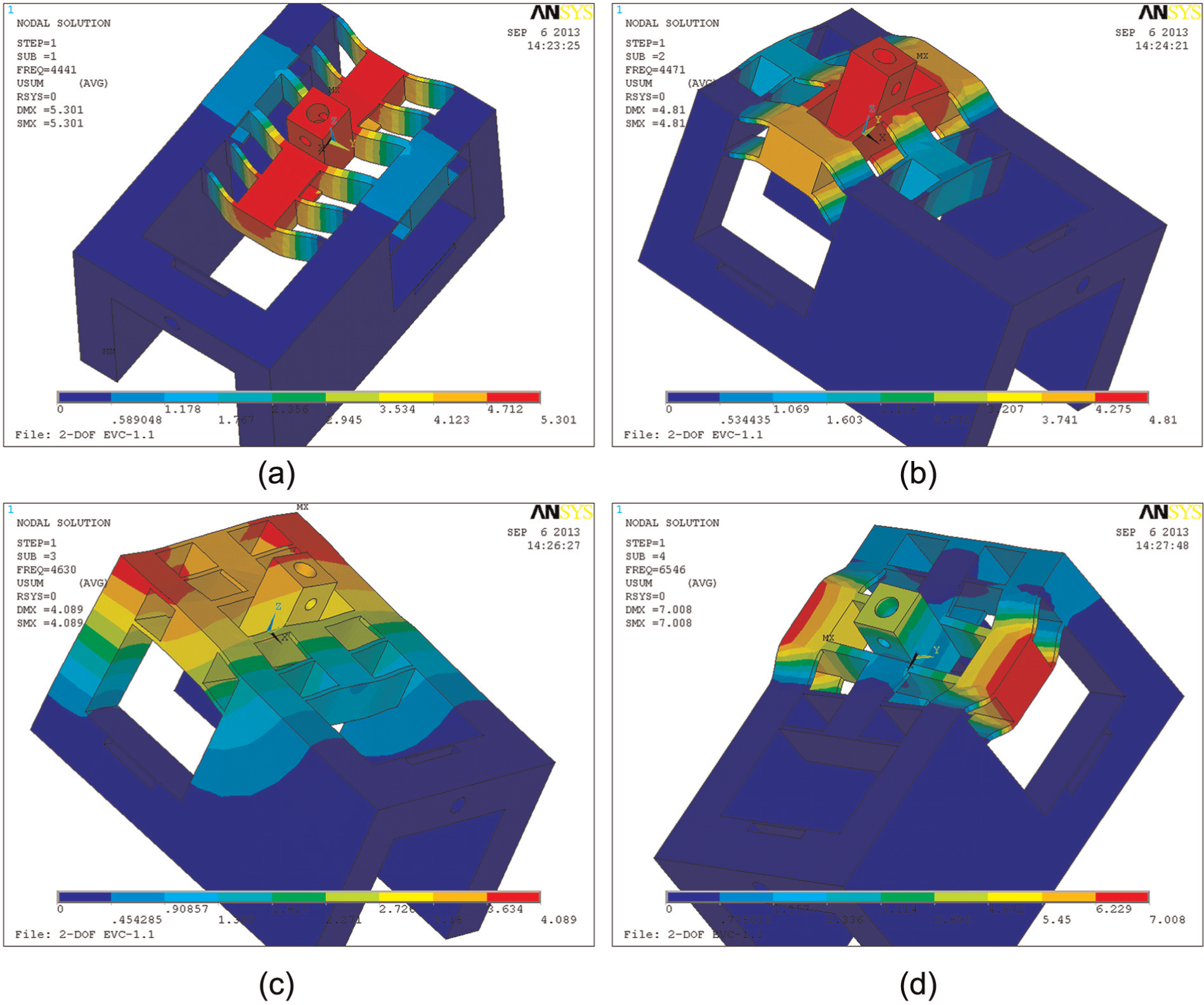
The first four modes of the flexural mechanism: (a) Mode 1 (4441 Hz), (b) Mode 2 (4471 Hz), (c) Mode 3 (6467 Hz), and (d) Mode 4 (8305 Hz).
Decoupling performance investigation
The decoupling effects comprise input decoupling and output decoupling, 2 the input decoupling means that one actuator would suffer no lateral damage motion induced by the motions of the other actuators, while the output decoupling suggests that no parasitic motion in other directions will occur when the platform is moving along one specified direction. As one of the most significant performances of the flexural mechanism, the decoupling capacity will be investigated with the FEA method in this section.
Two sequences of the driving forces along the y-axis and z-axis are first employed to investigate the output decoupling performances of the flexural mechanism, respectively. As shown in Figure 8, it can be observed that the obvious linear relationships between the output displacement and corresponding driving forces, while the induced coupling motions along the y-axis and z-axis also submit to linear laws, and the maximum of the coupling motions are 9 and 8 nm, respectively. In view of the corresponding output motions along the driving direction, the coupling motions are less than 0.1%, which can be totally ignored; all the results indicate that the 2-DOF flexural mechanisms possess high decoupling capacity.
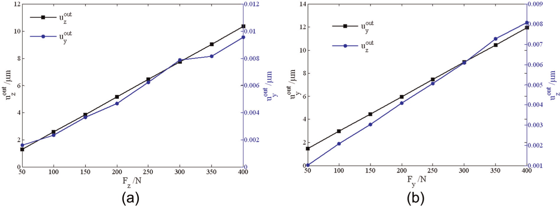
Output moving features of the flexural mechanism: (a) output motions in terms of the driving forces along z direction and (b) output motions in terms of the driving forces along y direction.
As for the input coupling, the motions along the driving direction will be resisted by the actuators or the preloads of flexural mechanism, leading to no negative effects on the PEAs. However, the lateral motions will introduce shear effects on the PEAs, which will raise the risk of the PEAs damages. In other words, it is critical that the motion of actuator is inherently constrained to move only along the driving direction, and this attribute is referred to as actuator isolation. 1
To investigate the actuator isolation attribute, the lateral motions of the middle points of the interfaces of the actuators and mechanism are obtained with FEA method, and illustrated in Figure 9. As shown in Figure 9, the input coupling motions are in direct proportion to the driving forces and possess obvious linear relationships. The input coupling
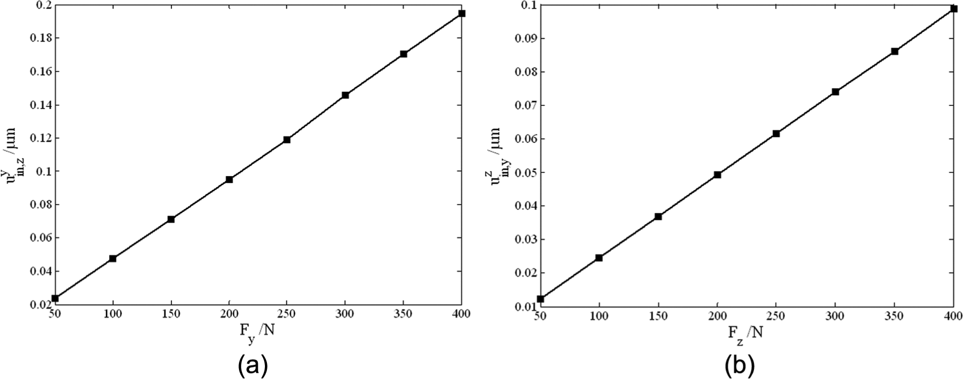
Input coupling of the flexural mechanism in terms of the driving forces along (a) y direction and (b) z direction.
Performances testing of the 2-DOF flexural mechanism
The photographics of the developed flexural mechanism and correlative experimental set are illustrated in Figure 10. Two capacity transducers with four measurement channels (Mode 5300, MicroSence Inc., USA) are chosen to measure dynamic position. Three piezoelectric stack actuators (P-880.51, Polytec PI, Inc., Germany) are employed for performance testing. A power amplifier module PI E-617 with a nominal amplification factor 10 ± 0.1 is chosen to amplify the driving signal of the PEAs. A Power PMAC (Delta Tau Inc., USA) is employed for gathering signals (sampled at 0.45 ms) and closed-loop control. In order to reduce external disturbances, all of the experiments are carried out on a vibration-isolated air-bearing platform (RS4000, Newport Inc., USA).
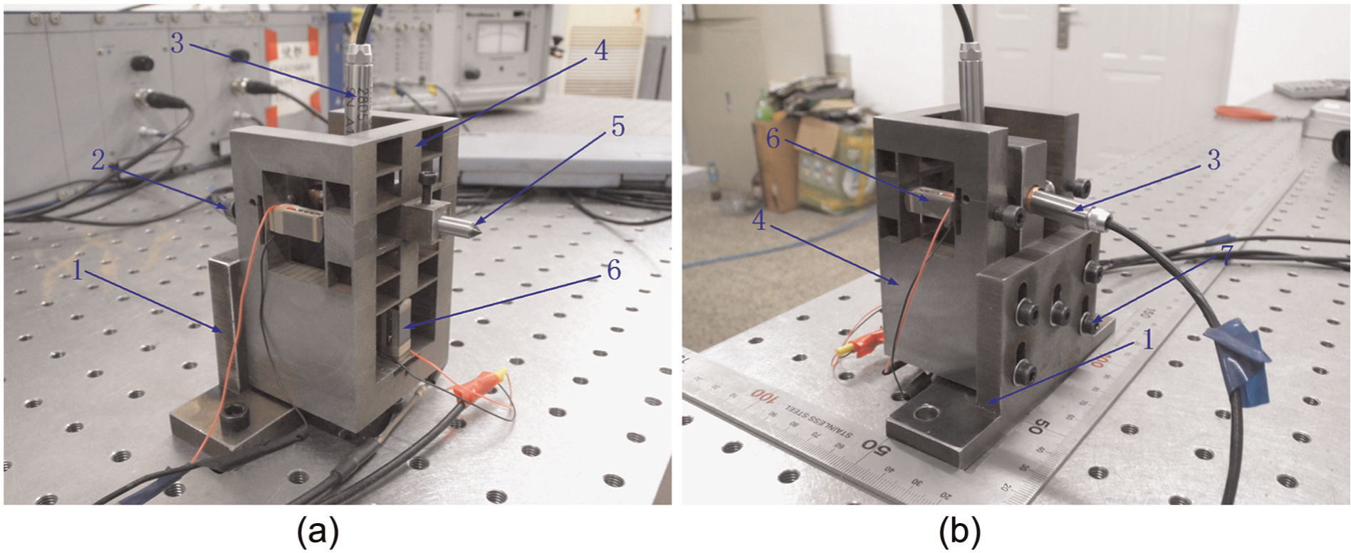
Photographs of the 2-DOF flexural mechanism (1: the base, 2: preloading screws, 3: probes of capacity transducers, 4: the 2-DOF flexural mechanism, 5: diamond tool, 6: the piezoelectric stack actuators, and 7: fastening screws). (a) Front view of the 2-DOF mechanism and (b) back view of the 2-DOF mechanism.
Static tests
To investigate the stroke along the z-axis, two completely synchronical and low-frequency harmonic driving voltages with 100 V peak, which is the maximum allowable voltage of the piezoelectric stack actuators, are applied to the two PEAs, resulting in the response shown in Figure 11(a), while the coupling motion in the y-axis direction during this process is also investigated and illustrated in Figure 11(b). Similarly, another harmonic driving voltage with same magnitude is then applied to another PEA to investigate the stroke along the y-axis and the coupling in the z-axis direction, the corresponding stroke and coupling are shown in Figure 12(a) and (b).
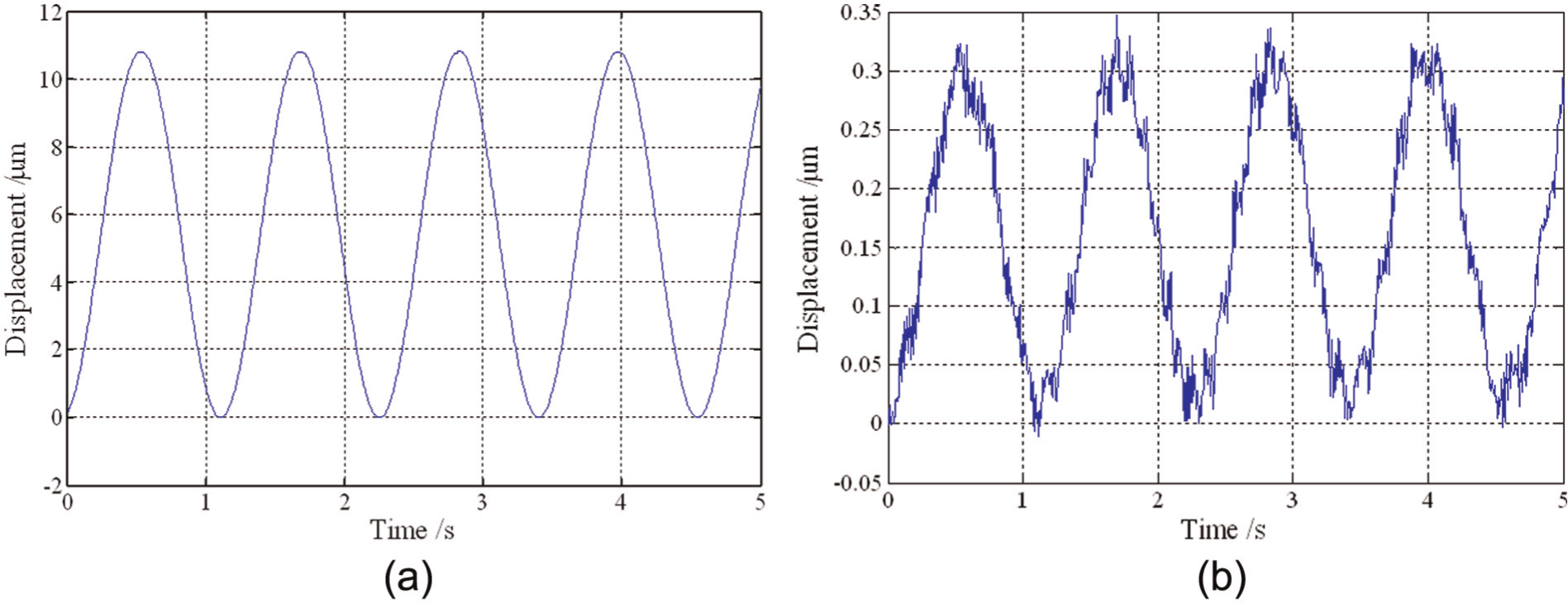
Moving features of the mechanism with driving forces along the z-axis: (a) the response along the z-axis and (b) the coupling along the y-axis.
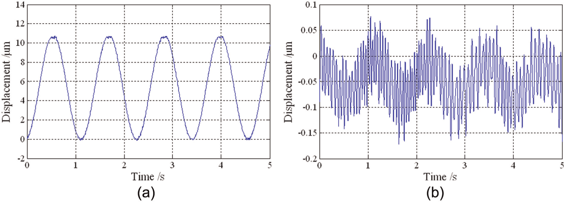
Moving features of the mechanism with single driving force along the y-axis: (a) the response along the y-axis and (b) the coupling along z-axis.
As shown in Figure 11(a), the stroke of the flexural mechanism along the z-axis can reach up to 10.82 µm. It should be noticed that the stroke (15 µm) of the actuators may be slightly higher than the practical stroke due to the preloading effects and input stiffness of the mechanism. However, it shows a good agreement between the theoretical and experimental results, demonstrating the accuracy of the developed model for the flexural mechanism. As shown in Figure 11(b), the peak-valley value of the induced coupling along the y-axis is about 0.35 µm, which is about 3% of the stroke. As for the motion along the y-axis shown in Figure 12(a), the stroke can reach up to 11.84 µm. As shown in Figure 12(b), the peak-valley value of the induced coupling along the z-axis is less than 0.35 µm, which is about 3.0% of the stroke. Generally, the couplings may be caused by various factors such as inconsistent preloads of the PEAs, inconsistent properties of the employed PEAs, structural asymmetries induced by manufacturing errors, the assembly errors, interference of the external environment, and so on. 24
Figure 13 is the principle of the motion along the z-axis; z1 and z2 denote the outputs of the two PEAs, respectively. If an output of the PEA does not synchronize with the other one, an undesired parasitic motion and rotation would greatly affect performances of the flexural mechanism. The undesired coupling in the x-axis direction, which is expressed as Δx, can be derived as follows
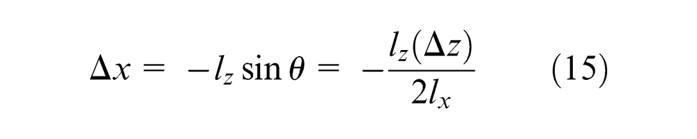
Principle of motion along z-axis.
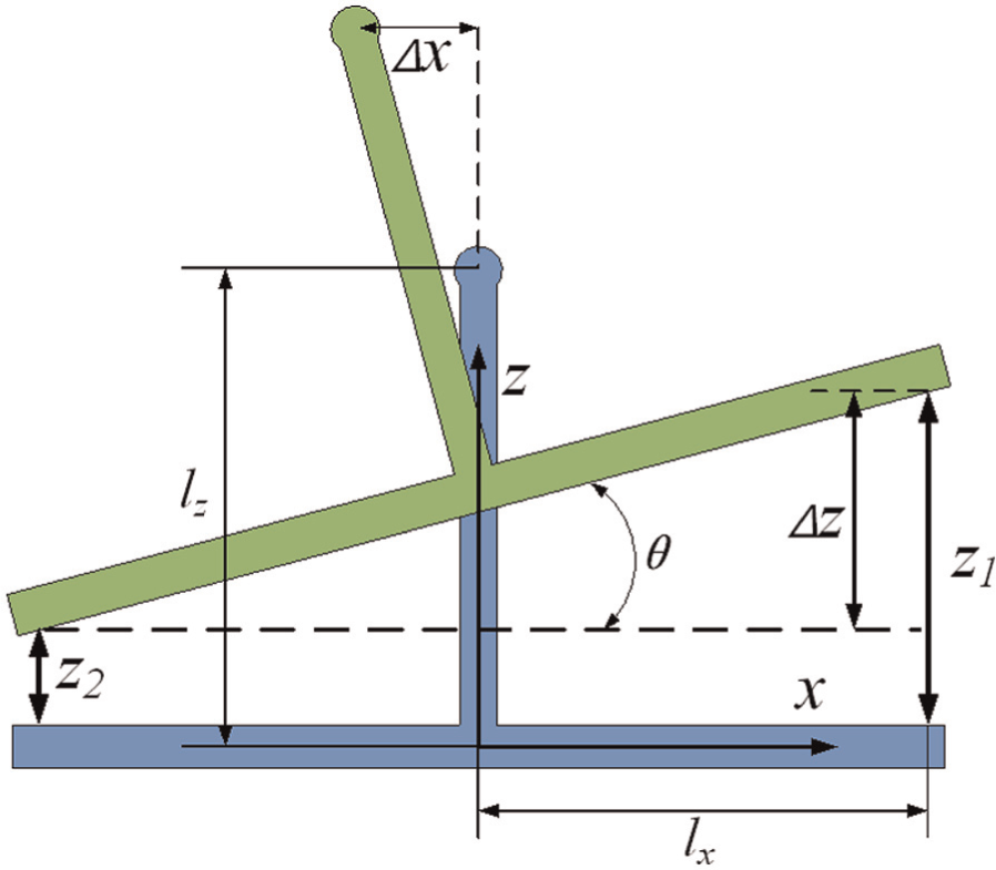
As shown in Figure 13, the output displacements of the two PEAs could not be perfectly synchronical in practical driving process. As a result, an extra output difference between the two actuators, which is defined as Δz in equation (15), would be induced by various kinds of complex factors such as inconsistent preloads and properties of actuators, noise of external environment, manufacturing errors, and so on. The resulted coupling in x-axis direction by the mentioned output difference is illustrated in Figure 14. Moreover, the two PEAs can be actuated by differential driving signals with different phase or amplitude if necessary; as a result, the proposed 2-DOF flexural mechanism will obtain extra rotary movement around the y-axis and convert to a three-degree-of-freedom (3-DOF) flexural mechanism.
Coupling features of the mechanism with driving forces along the x-axis: (a) motions of the double piezoelectric actuators and (b) the experimental coupling along x-axis.
As shown in Figure 14, the outputs of the two actuators show a good consistency and synchronism, and experimental coupling in the x-axis direction is about 0.35 µm, which is less than 3% of the stroke in the z-axis direction. However, all of experimental results would demonstrate the excellent performances of the 2-DOF flexural mechanisms. In view of the perfect theoretical couplings which are close to zero, the proposed flexural mechanism has a great potential to obtain better decoupling performance in future work.
Dynamics performance tests
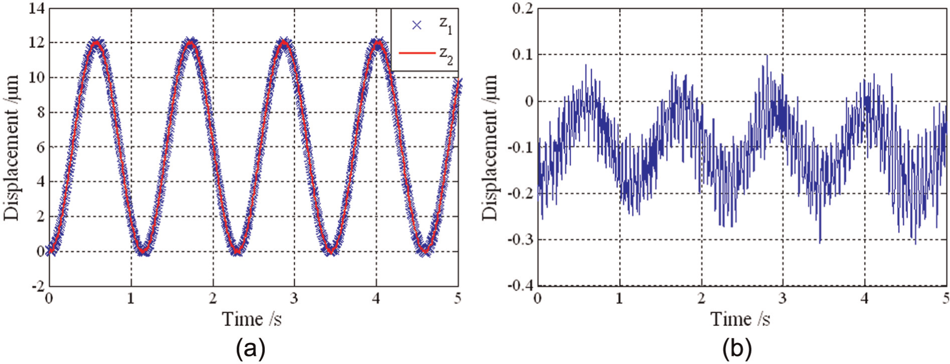
Since the contact conditions will significantly influence the dynamics of the flexural mechanism,18,25 the sweeping excitation method is employed to analyze the dynamics of mechanism instead of harmer-based impact analysis method. By conducting Fourier transform of both the excitation and response signals, the obtained amplitude–frequency response (AFR) of the two moving directions are illustrated in Figure 15. As shown in Figure 15, the first resonant frequencies of the z-axis and the x-axis are about 420 and 450 Hz, respectively. However, the experimental resonant frequencies are much lower than the results obtained by the FEA model. The huge errors derive from the FEA results which come from a free structure without taking actuators into account. Besides, other reasons which may greatly influence the equivalent dynamic stiffness, such as the imperfect contacts and preloads of actuators, would decrease work bandwidth of the compliant system. Thus, improving the contact conditions should be considered in the future to take full advantage of the high bandwidth of the flexural mechanism, 24 but the preloads ought to be reasonably exerted.
Amplitude–frequency response (AFR) of the mechanism: (a) z-axis and (b) y-axis.
Closed-loop performance testing
In general, the inherent nonlinearities of piezoelectric stack actuators, the asymmetry, and the external forces will significantly deteriorate positioning accuracy of the flexural mechanism. To compensate these undesired motions errors, a universal method is used for constructing a feedback control system for the mechanism, the displacements of the output end in the two directions of motion are measured and directly served as the feedback signals of closed-loop control. Meanwhile, a simple proportional, integral, and derivative (PID) controller is employed. The step responses in the two directions are tested with the purpose of investigating the platform positioning performance, resulting in the responses shown in Figure 16. As shown in Figure 16, the arise times of the z-axis and y-axis directions are about 5.4 and 4.6 ms, respectively. The two perfect response curves indicate that the mechanism can rapidly follow external commands with no steady errors and no overshoots during the positioning process. All the observed results demonstrate that the developed 2-DOF flexural mechanism can rapidly respond to commands with the high accuracy, and it is very suitable for micro/nanomeasuring and ultraprecision machining.
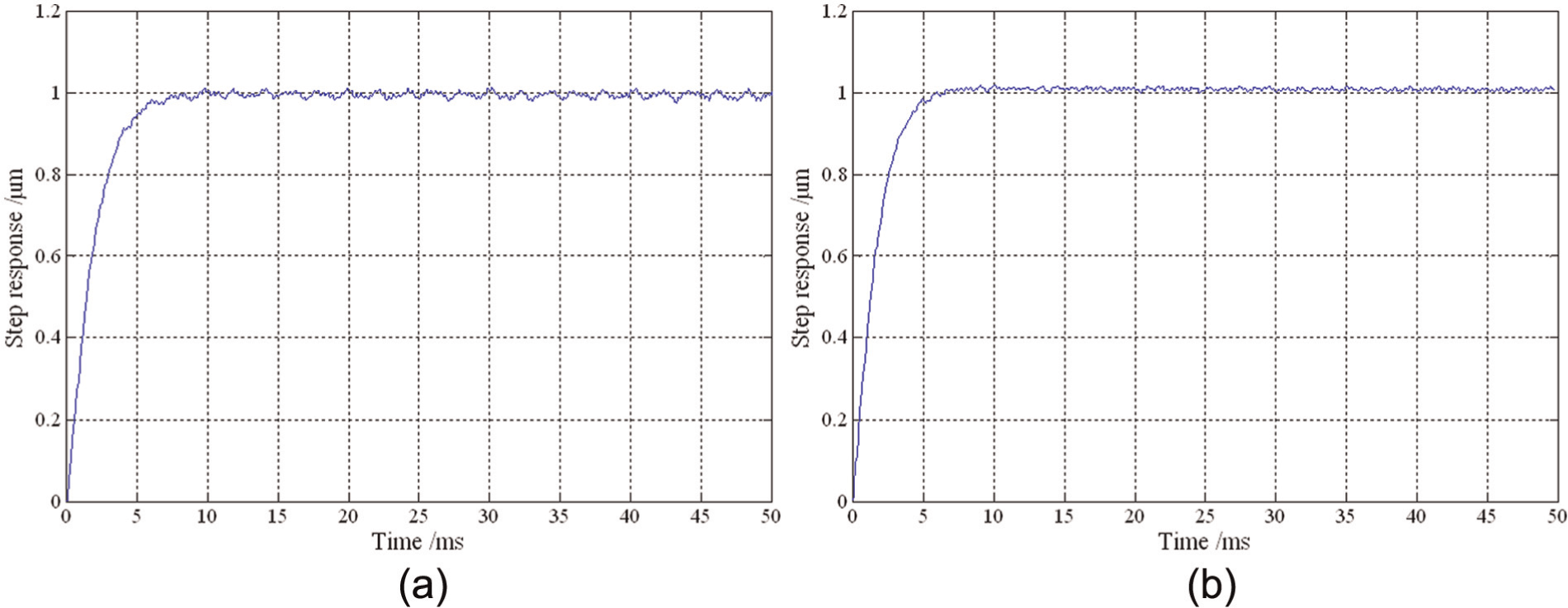
Step responses of the 2-DOF mechanism along (a) the z-axis and (b) the y-axis.
Conclusion
In this article, a novel 2-DOF flexural mechanism with decoupling motions, which can be applied to precision engineering, is developed to realize the accurate servo motions in two directions of motion. To investigate the performances analytically, the kinematical model of the flexural mechanism is theoretically modeled based on the matrix modeling method. Then, both FEA and experimental test are conducted to validate the theoretical results and to obtain the practical performances of the flexural mechanism. The main conclusions can be summarized as follows:
A novel PKCM method is developed to achieve totally geometric decoupling and the actuator isolation, which can effectively solve the overconstraint of flexural mechanisms through the corresponding kinematical schematics.
The elastic deformation behavior, and the input and output compliances of the flexural mechanism are analytically modeled by means of the MCM method. The theoretical results are validated by FEA, and the good agreement between the theoretical and the FEA results demonstrate the efficiency of the analytical model for describing the dynamics of the mechanism.
FEA is conducted on investigating the coupling behavior of the flexural mechanism. About 1% input coupling motions can be observed caused by the motions along y-axes and z-axes, which can satisfy accuracy requirement in most cases. And the output couplings in different motion directions are less than 5%. All obtained results demonstrate an available decoupling property of the newly developed mechanism.
By experiment tests, the stroke along the z-axes can reach up to 10.82 µm, while that along the y-axes are 11.84 µm. And the practical coupling motions in the three different directions are less than 3%. By sweeping tests, the obtained bandwidth of the system can reach up to 420 and 450 Hz, respectively.
A simple PID controller is employed to eliminate the nonlinearity of PEAs and the external disturbance. The raise times of step responses are about 5.4 and 4.6 ms in the z-axis and y-axis, respectively, which indicate that the designed performance of the proposed 2-DOF flexural mechanism is superior to most existing flexural mechanisms.
Footnotes
Declaration of conflicting interests
The authors declare that there is no conflict of interest.
Funding
The authors are grateful to the financial support from the National Natural Science Foundation of China (51175221, 51375060).