This research presents the design, implementation, and experimental validation of a robust control system for a human-scale Segway-type wheelchair. Two distinct control strategies—a standard linear quadratic regulator (LQR) and a robust controller—are synthesized based on a linearized state-space model and implemented on an STM32 microcontroller. The study conducts comparative experiments to evaluate real-world performance under parametric uncertainty and impulsive disturbance scenarios. While both controllers achieve stability under nominal conditions, their performance diverges significantly in the presence of uncertainty. Experimental results demonstrate that the controller maintains robust stability against substantial parametric variations and impulsive external forces, whereas the LQR destabilizes under these conditions. Consequently, this work confirms that control offers superior robustness and reliability for balancing platforms operating in unpredictable environments.
The evolution of two-wheeled self-balancing (TWSB) vehicles has shifted from a theoretical benchmark in control theory to a practical solution for modern mobility. Following the seminal work on the JOE mobile inverted pendulum,1 these underactuated systems have attracted sustained research attention due to their nonholonomic constraints and inherent open-loop instability. Particularly within the domain of assistive technology, two-wheeled robotic wheelchairs offer transformative potential. In contrast to conventional four-wheeled architectures, TWSB platforms feature a zero turning radius and a compact footprint, facilitating navigation through narrow corridors and cluttered indoor environments with superior agility.2,3 However, this agility necessitates active balancing, rendering the system highly susceptible to instability induced by external disturbances or center of gravity (CG) variations.4
Conventional control strategies for TWSB systems have predominantly employed proportional-integral-derivative (PID) control, favored for its ease of implementation on embedded hardware.5,6 Although effective for stationary balancing, PID approaches often fail to adequately decouple the nonlinear dynamics of yaw and pitch, necessitating extensive manual tuning and offering limited adaptability to varying operating conditions.7 To enhance stabilization performance, linear quadratic regulators (LQRs) and linear quadratic Gaussian (LQG) control have been widely adopted.8,9 By minimizing a quadratic cost function, LQR optimizes the trade-off between state deviation and control effort, theoretically yielding the optimal control action.10 However, optimal control methods are inherently sensitive to parametric uncertainty. As noted in recent studies,11,12 standard LQR performance degrades rapidly when the physical system deviates from the nominal mathematical model—a critical vulnerability for balancing platforms subject to significant variations in payload mass and center of gravity distribution.
To mitigate this sensitivity, recent literature has shifted toward nonlinear and intelligent control frameworks. Sliding mode control (SMC) has been proposed to guarantee robustness against matched disturbances by confining the system states to a sliding surface.13,14 Although theoretically robust, SMC often induces chattering (high-frequency oscillation) in the control signal. In electromechanical platforms, this phenomenon leads to excessive actuator wear, increased energy consumption, and the potential excitation of unmodeled high-frequency dynamics, which can compromise mechanical integrity over time.15 Alternatively, data-driven approaches, including neural networks16 and reinforcement learning,17 have emerged to handle variable loads without explicit modeling. However, these learning-based methods often lack the analytical stability guarantees required for predictable operation in dynamic environments. Finally, nonlinear model predictive control (NMPC) has demonstrated superior trajectory tracking capabilities,18 yet its high computational demand imposes substantial hurdles for real-time implementation on resource-constrained embedded platforms.
These trade-offs highlight a critical gap in the literature for a control strategy that combines the stability margins of optimal control with the uncertainty tolerance of robust control, while avoiding the chattering of SMC and the computational burden of NMPC. The control framework, established in foundational works,19,20 offers a principled solution by minimizing the worst-case gain from disturbances to error. Recent experimental validations in multivariable systems21,22 confirm the theoretical efficacy of synthesis in rejecting exogenous disturbances while ensuring smooth control action. Furthermore, saturation mitigation strategies address actuator limits in self-balancing platforms,23 underscoring the enduring relevance of robust linear synthesis for underactuated systems.24
Despite these theoretical advances, the experimental validation of robust controllers on human-scale TWSB platforms remains limited. As highlighted in a recent review,25 many studies are restricted to numerical simulations or small-scale laboratory prototypes that do not capture the complex inertial dynamics of variable high-mass payloads. Furthermore, ensuring stability under heavy load variations remains a persistent challenge for two-wheeled vehicles operating in complex terrain.26 This research addresses this gap by designing, implementing, and experimentally validating a robust controller for a robotic wheelchair platform. We provide a comparative analysis against a baseline LQR, explicitly quantifying the system’s ability to recover from impulsive disturbances and maintain stability under substantial parametric mass variations.
System modeling
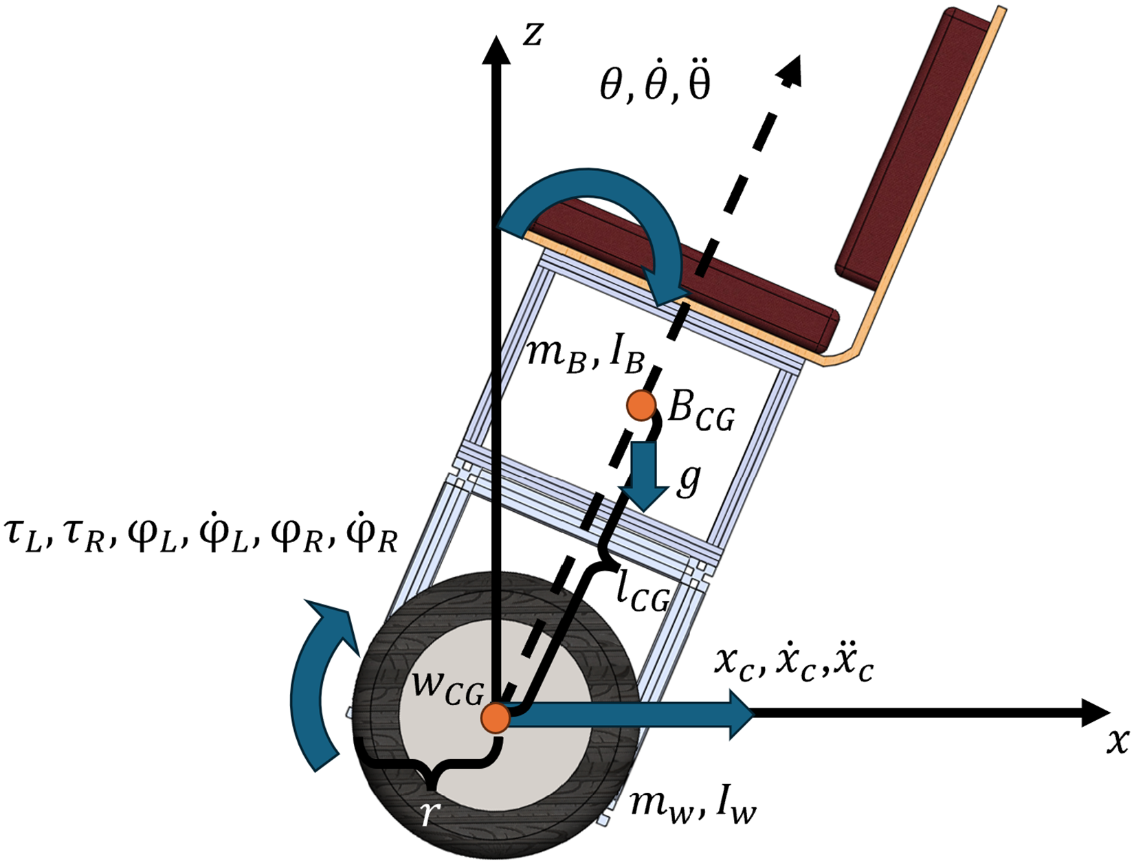
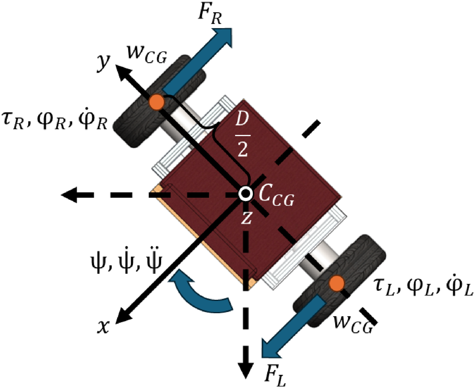
The dynamic behavior of the TWSB wheelchair is characterized using a mathematical model derived via the Euler–Lagrange formulation. Consistent with established modeling frameworks for self-balancing two-wheeled vehicles,1 this energy-based approach captures the inherent instability of the platform where active control is requisite. To facilitate linear control synthesis, the system dynamics are decoupled into longitudinal motion (governing displacement and pitch) and rotational yaw dynamics. The fundamental kinematic variables and forces are illustrated in the free body diagrams in Figure 1 (side view) and Figure 2 (top view), which define the generalized coordinates for the subsequent Lagrangian analysis.
Side-view free body diagram of the seat-type balancing robot showing tilt dynamics.
Top-view free body diagram illustrating yaw and turning dynamics.
System parameters and generalized coordinates
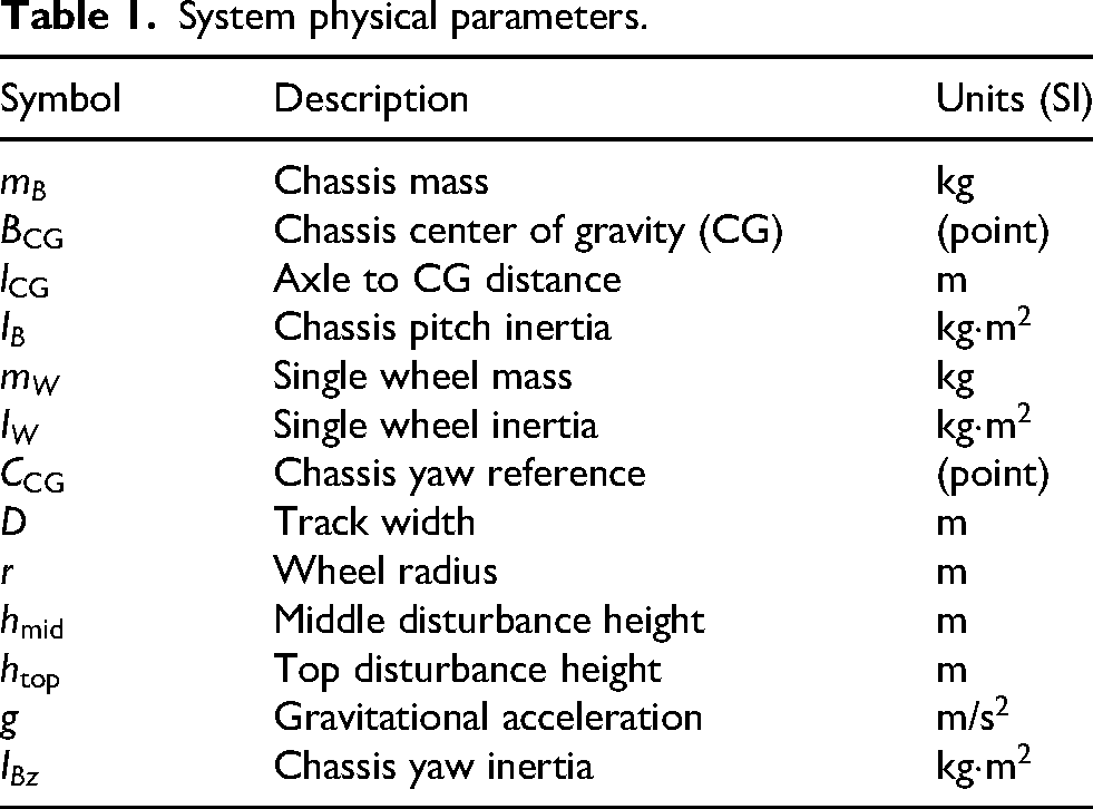
The physical parameters of the TWSB wheelchair are detailed in Table 1. Subsequently, the set of generalized coordinates characterizing the system configuration is defined in Table 2.
System physical parameters.
Symbol
Description
Units (SI)
Chassis mass
kg
Chassis center of gravity (CG)
(point)
Axle to CG distance
m
Chassis pitch inertia
kgm
Single wheel mass
kg
Single wheel inertia
kgm
Chassis yaw reference
(point)
Track width
m
Wheel radius
m
Middle disturbance height
m
Top disturbance height
m
Gravitational acceleration
m/s
Chassis yaw inertia
kgm
Generalized coordinates of wheelchair dynamics.
Symbol
Description
Units (SI)
Chassis pitch angle
rad
Chassis yaw angle
rad
Vehicle displacement
m
Left wheel angle
rad
Right wheel angle
rad
Mathematical modeling via Euler–Lagrange
In this study, the dynamic equations of the system are derived using the Euler–Lagrange method.27 This approach relates the system’s energy properties to its motion dynamics. The general Euler–Lagrange equation is expressed as:
where represents the generalized coordinates, denotes the generalized forces, and is the Lagrangian function.
To apply this method, the system’s Lagrangian () must be formulated. The Lagrangian is defined as the difference between the total kinetic energy () and the total potential energy ():
Consequently, the following subsections derive the kinetic and potential energy formulations required to solve Eq. (1).
Kinetic energy formulation
The total kinetic energy () comprises the sum of the energies of the chassis and the two wheels.2
The kinetic energy of the chassis () arises from a combination of its translational, pitching, and yawing motions. It is expressed as:
The kinetic energy of the wheels () consists of both translational and rotational components. Assuming a no-slip condition where , the energy for both wheels is given by:
Potential energy formulation
The total potential energy () is the sum of the potential energies of the chassis and the wheels:
By defining the reference level () at the wheel axles, the potential energy of the wheels vanishes (). The potential energy of the chassis depends on the vertical height of its center of mass () and is expressed as:
Derivation of equations of motion
Substituting the derived energy expressions into the Lagrangian (Eq. (2)) yields:
We now apply the Euler–Lagrange equation (Eq. (1)) to this Lagrangian for each generalized coordinate.
Equation of motion in Yaw () axis
For the yaw motion (), the partial derivatives of the Lagrangian with respect to the generalized coordinate and its rate are:
The generalized torque governing yaw rotation arises from the differential tractive forces of the right () and left () wheels.
Substituting these components into the Euler–Lagrange equation (1) results in the final equation of motion for the yaw axis:
Equation of motion in pitch () axis
The equation for the pitch motion is derived for the coordinate . The terms of the Euler–Lagrange equation with respect to the pitch angle and the pitch rate are determined from the following equations.
Taking the time derivative of the equation (14) yields the following result:
The generalized force in the pitch axis, , is the sum of the reaction torques of the motors that act on the chassis:
Substituting these components into the Euler–Lagrange equation (1) and simplifying the result yield the final equation of motion in pitch axis.
Equation of motion for forward motion ()
The equation of motion for the forward motion, , is required in position control. The terms of the Euler–Lagrange equation with respect to the position and the velocity are determined from the following equations.
Equation (20) is zero because the Lagrangian does not depend on the position , but depends on its velocity. Taking the time derivative of equation (19) yields:
The generalized force for forward motion, , is the sum of the traction forces from both wheels, generated by the motor torques:
Substituting these components into the Euler–Lagrange equation (1) results in the equation of motion of the forward motion.
Motor dynamics
To relate the control inputs to the physical system, dynamic models of the geared DC motors are required.27 The model for each motor is characterized by its electrical parameters (armature resistance , torque constant , back-EMF constant ) and mechanical parameters (rotor inertia , viscous friction ), scaled by the gear ratio . By assuming , the resulting motor dynamics define the output torque at the wheel () as a function of the applied voltage () and the wheel’s angular motion ():
Assuming a no-slip condition where , this torque can be expressed in terms of the wheelchair’s linear motion:
Linearization and state-space model
The equations of motion derived via the Euler–Lagrange method are inherently nonlinear. To facilitate the design of linear control strategies, these dynamics are linearized around the unstable upright equilibrium point. This linearization employs standard small-angle approximations:1,27
Applying these approximations allows the system dynamics to be reformulated into the standard state-space representation:25
The state vector is chosen as:
The input vector consists of the left and right motor voltages:
State-space representation
The linearized dynamics are formulated into the state-space representation. The nominal system matrix and control input matrix are structured as follows:
Disturbance modeling
For the purpose of robust controller design and rejection analysis, this nominal model is augmented to include external disturbances. The model considers horizontal disturbance forces applied at two distinct locations on the chassis: a force at the middle height () and a force at the top (). This results in the augmented state-space equation:
where the disturbance vector and the disturbance distribution matrix are defined as:
Physically, these forces generate different disturbance torques on the chassis depending on their respective lever arms ( and ).
The analytical derivation of all system matrices () and the explicit expressions for their elements are detailed in Appendix A. The numerical values for the system parameters used in these matrices are listed in Table 3 within Appendix B.
Controller design
To achieve stable balancing and robust performance, two control strategies are designed and implemented for the Segway-type wheelchair. The first control, a LQR, serves as an optimal control baseline under nominal conditions. The second control, an controller, is synthesized to explicitly address model uncertainties and external disturbances, which exist in real-world operation. Both controllers are based on the linearized state-space model derived in Section.
Linear quadratic regulator (LQR) design
The LQR control law is defined as , where the gain minimizes the cost function:
The primary objective for the LQR design is to achieve stable balancing while maintaining the wheelchair’s position. The weighting matrices and are selected based on the system requirements:
The selection of the state penalty matrix is designed to manage the trade-off between station-keeping accuracy and vertical stabilization effort. A dominant penalty of is assigned to the translational position (). Since the system is underactuated, position correction is dynamically coupled to the pitch angle; linear acceleration requires a transient tilt. Therefore, strictly penalizing position error is necessary to induce sufficient pitch authority for drift rejection. A secondary but substantial penalty of is applied to the pitch angle () to bound the tilting excursions, ensuring the operating point remains within the linear region around the upright equilibrium. The yaw states () are assigned moderate penalties to maintain heading without over-constraining the primary longitudinal dynamics.
The control effort penalty matrix, , is selected as the identity matrix. This choice provides a balanced penalty on the motor voltage, allowing for control actions that are sufficiently aggressive for stability without demanding excessive voltage that could cause actuator saturation. The state-feedback gain matrix is computed by solving the continuous-time algebraic Riccati equation.
controller design
Although LQR provides optimal performance based on the nominal system, it lacks robustness against model uncertainties and external disturbances.28,29 To address this problem, a robust controller is synthesized using the standard optimal control framework. This approach finds a stabilizing controller, , for a given system—represented as a generalized plant —that minimizes the -norm of the closed-loop transfer function from exogenous inputs to the performance outputs .
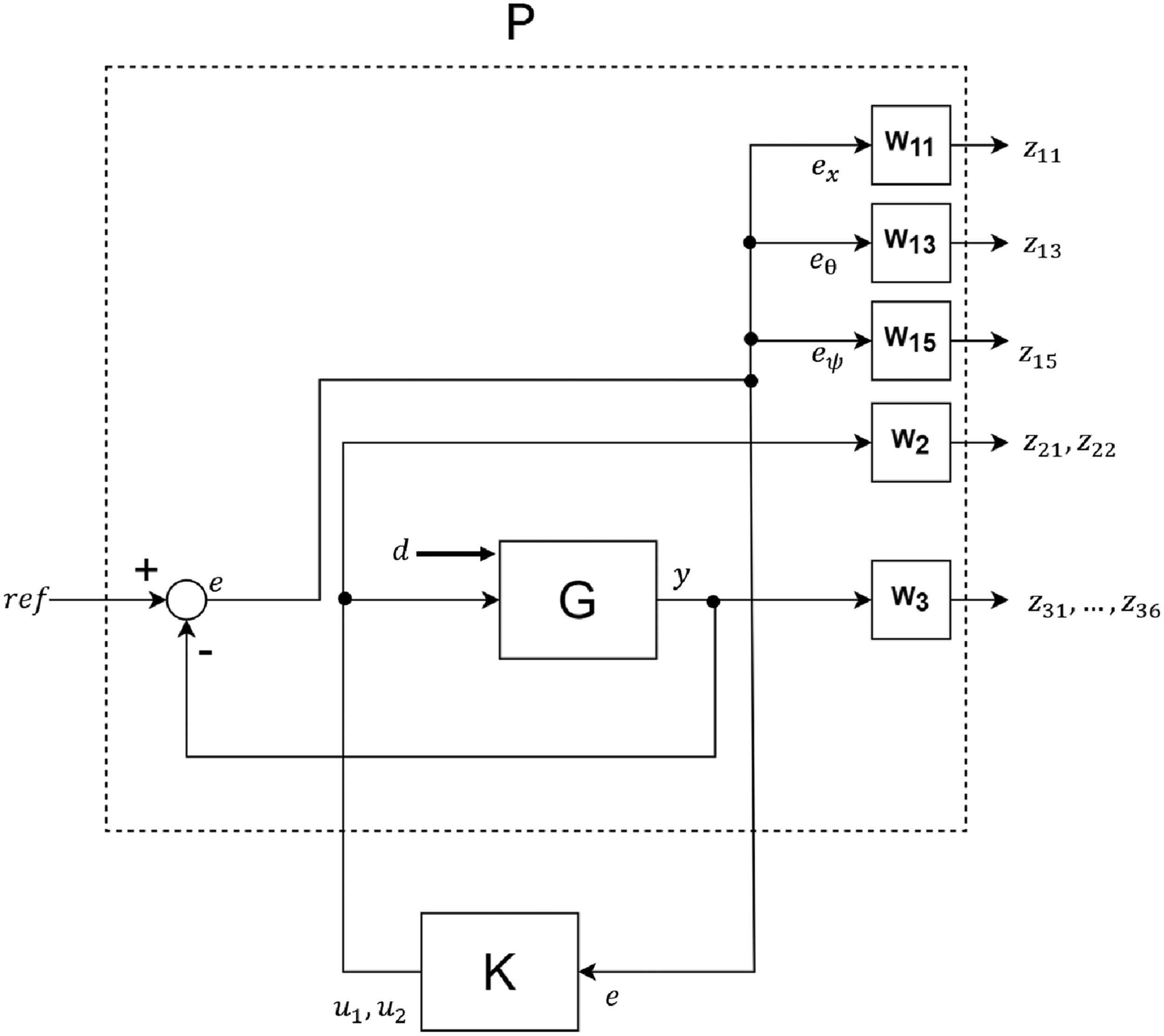
The core of the design process lies in the construction of the generalized plant , which augments the nominal wheelchair dynamics, , with a set of frequency-dependent weighting functions. These functions explicitly define the performance objectives and robustness requirements of the closed-loop system. The complete interconnection structure is depicted in Figure 3. The synthesized controller computes the control input based on the tracking error to force the system to follow a reference trajectory while attenuating input disturbances .
Plant augmentation for the weighted controller design. The physical plant G is augmented with weighting functions to create the generalized plant P.
Weighting function selection
The weighting functions , and are selected to shape the closed-loop sensitivity () and complementary sensitivity () functions. The selection process utilizes a theory-guided iterative approach,28 where baseline parameters are analytically derived from the frequency-domain limitations of the underactuated system—specifically the unstable poles and non-minimum phase (NMP) zeros—and subsequently refined via simulation to balance disturbance rejection against actuator saturation.
Performance weights ()
Performance weights define the desired shape of the sensitivity function to enforce tracking and disturbance rejection. The weighting function for position error, , is designed as a low-pass filter:
The DC gain of 0.05 is tuned to enforce a tracking constraint. Unlike fully actuated systems, tight position tracking at low frequencies can conflict with the stabilization objective, so this reduced value allows the controller to prioritize upright stability over precise position holding during large disturbances. The bandwidth is strictly limited to 2 rad/s, an upper bound theoretically imposed by the presence of a NMP zero in the force-to-position transfer function. As established in the foundational control literature,19,30 the closed-loop bandwidth must be restricted to a fraction of the NMP zero location to satisfy fundamental sensitivity conservation constraints and prevent excessive peaking in the sensitivity function. The high-frequency zero at 50 rad/s is determined through simulation to adjust the roll-off rate, ensuring adequate noise attenuation while maintaining stability margins.
The weighting function for the pitch angle, , is tuned with a slightly higher bandwidth of 2.5 rad/s:
Unlike the position loop, the pitch dynamics are governed by an unstable pole. This pole establishes a theoretical lower bound for the required response speed of the system, since the control loop must be faster than the dynamics of the instability to maintain equilibrium.1,31 Although this theoretical bound requires a fast closed-loop response, the specific corner frequency of 2.5 rad/s is determined iteratively through simulation. The selected parameter secures the stabilization of the unstable pole by enforcing high gain in the low-frequency region, but limits the bandwidth to prevent the amplification of high-frequency sensor noise. The DC gain of 0.02 is chosen to minimize steady-state pitch error while preventing actuator saturation during aggressive maneuvers.
Finally, for the yaw angle, the weighting function is explicitly defined as a constant scalar gain:
This low magnitude assigns a lower priority to heading regulation relative to the critical stability tasks (pitch and position), ensuring that the controller resources are primarily allocated to maintaining the rider’s safety.
Control effort weight ()
The control effort weight is selected as a static scalar gain:
The magnitude of 0.001 is determined iteratively based on simulation results to map the mathematical optimization cost to the physical voltage limits of the hardware. This value imposes a penalty on the control signal that limits the peak motor voltage to prevent actuator saturation while maintaining sufficient authority for robust stabilization.
Robustness weight ()
The robustness weight shapes the complementary sensitivity function to enforce stability in the presence of multiplicative uncertainty :
The parameters are selected to characterize the specific uncertainty profile of the platform. The low-frequency gain of 0.01 reflects the high accuracy of the linearized model near the equilibrium point, assuming only 1% uncertainty in steady state. The corner frequency of 25 rad/s marks the bandwidth where unmodeled dynamics, such as structural flexibility and motor electrical dynamics, become significant. To ensure that the weighting function remains proper and physically realizable, a high-frequency pole is placed at 25,000 rad/s, well beyond the control bandwidth. Based on the Small Gain Theorem,20,29 this design ensures robust stability provided that . The high-pass structure of restricts the complementary sensitivity to roll off at high frequencies, effectively suppressing sensitivity to unstructured uncertainty.
Simulation results
To evaluate the performance of the designed controllers, a series of simulations is conducted. The following sections present a comparative analysis of the LQR and controllers under both initial condition offsets and external disturbances.
Position control under different Initial conditions
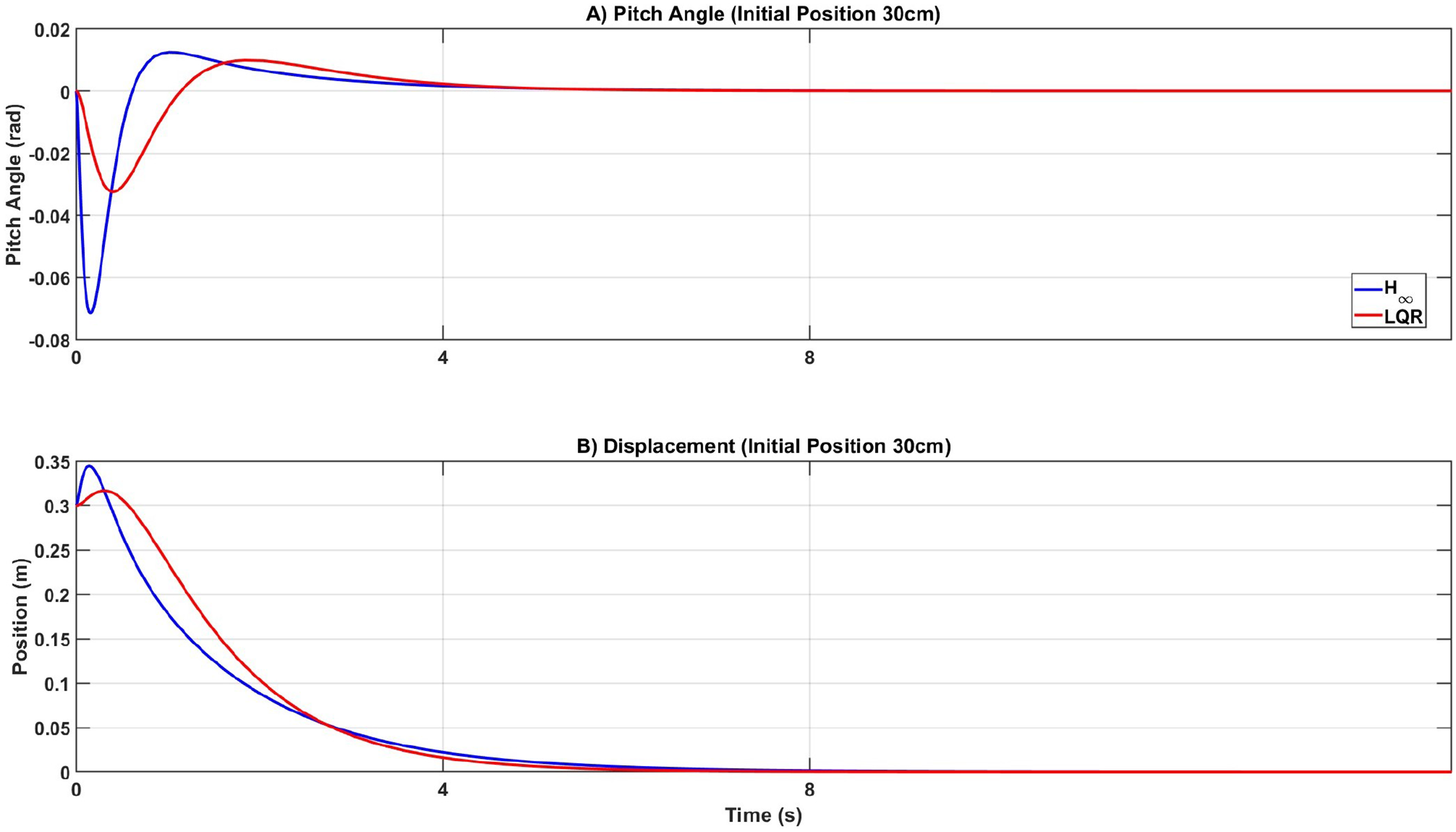
The first simulation evaluates the performance of both controllers in longitudinal regulation. The system is initialized with a displacement of 30 cm, while all other states are set to zero. The objective is to return the wheelchair to the equilibrium point ().
The results in Figures 4 and 5 illustrate the baseline characteristics of each strategy. As expected for a nominal system, the LQR controller provides the superior response. It returns the system to the origin with a smooth trajectory and minimal tilt oscillation. In contrast, the controller exhibits a more aggressive transient response, resulting in a larger initial pitch angle deviation ( rad versus rad for LQR).
Comparison of system response from an initial offset of 30 cm. The LQR is smoother and optimal, while the shows higher transient oscillation.
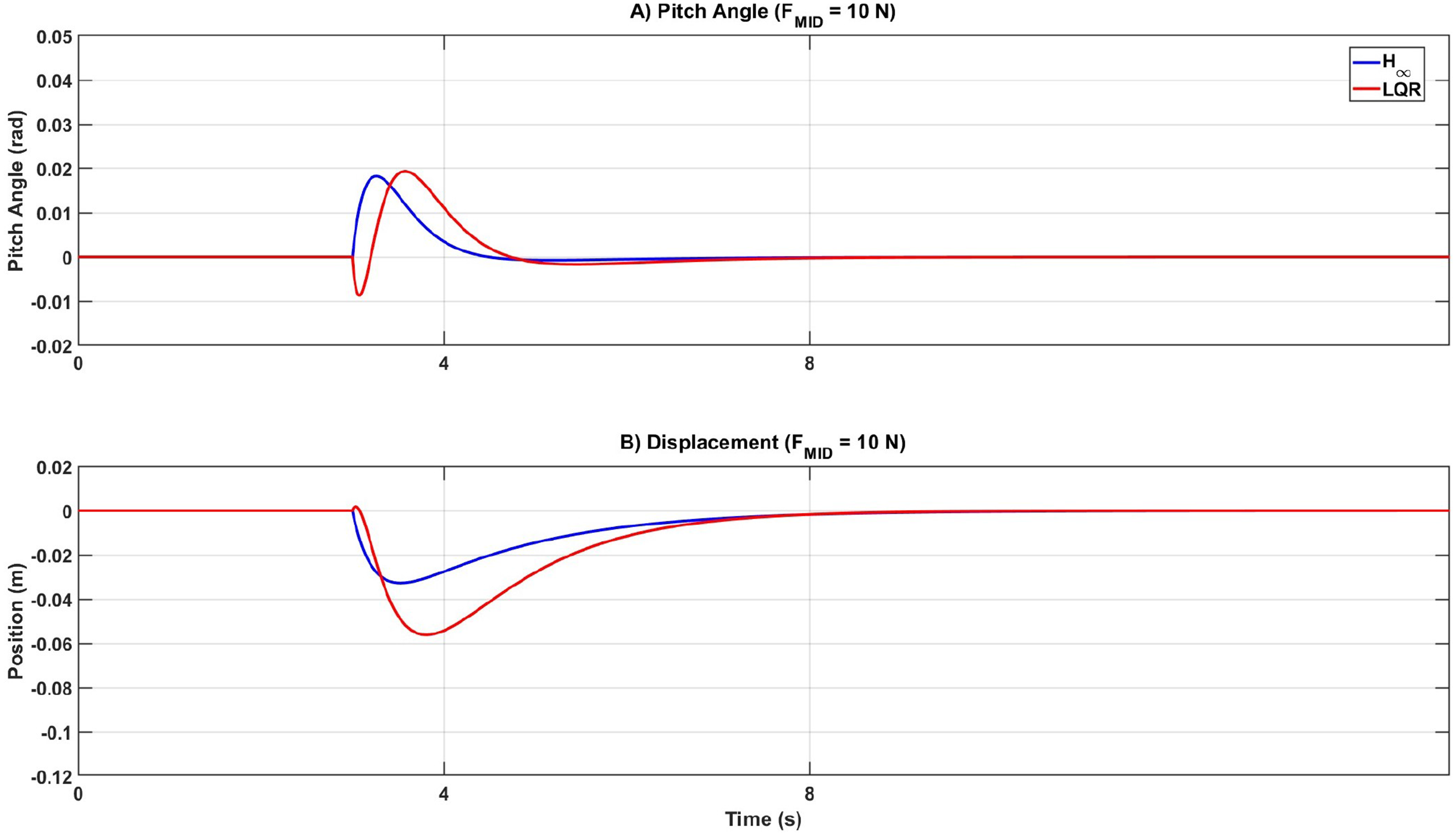
Comparison of system response to a nominal impulse disturbance ( N).
This comparison highlights a fundamental trade-off in control design. The LQR achieves better performance in this idealized scenario because it is tuned for optimality on the exact mathematical model. The controller’s slightly degraded nominal performance (larger transient oscillation) represents the inherent cost required to secure the robustness margins necessary for real-world operation.
Disturbance rejection
To quantify the disturbance rejection capabilities, an impulsive external force of 10 N is applied to the system. The response is analyzed under two distinct loading scenarios: a nominal disturbance applied at the chassis center of mass, and a critical high-torque disturbance applied at the upper backrest.
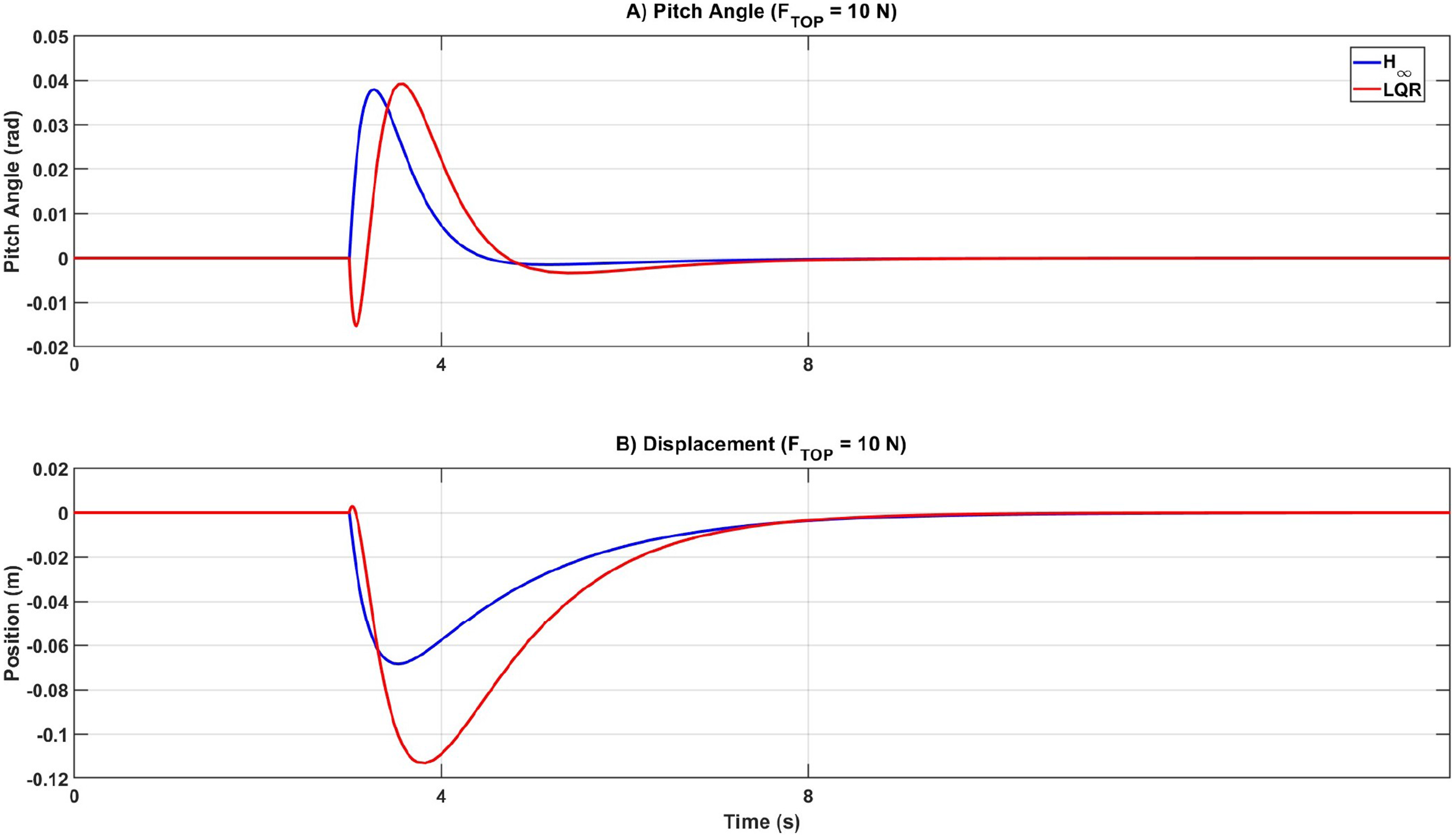
While LQR demonstrated superior tracking in the nominal case, the results presented here establish the robust performance of the controller under external perturbations. As shown in Figure 6, under the critical top-heavy disturbance scenario, the controller significantly attenuates the impact, constraining the maximum displacement excursion to 6.8 cm. In contrast, the LQR allows a deviation of 11.3 cm, nearly double that of the robust controller.
Comparison of system response to a critical high-torque impulse disturbance ( N).
The pitch angle response further corroborates this advantage. The controller suppresses the transient oscillations more effectively, achieving a settling time that is 33.7% faster than the LQR baseline. This performance validates the effectiveness of the loop-shaping strategy in minimizing the system’s sensitivity to external torques.
Robustness to parametric uncertainty
The final simulation evaluates the system’s robustness under severe parametric uncertainty. To validate the control law against physical variations, the plant parameters are subjected to significant deviations from the nominal model. The chassis mass is increased by 100% to simulate a maximum heavy-payload scenario. Concurrently, the available actuator torque is reduced by 20% to account for thermal degradation and voltage sag inherent in portable power systems,32 while unmodeled actuator saturation is introduced to test nonlinear stability limits.33
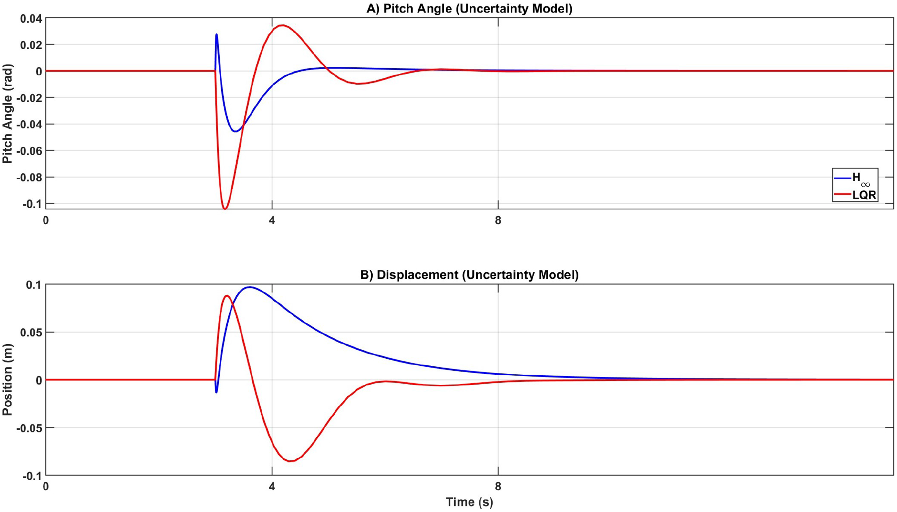
The superiority of the robust synthesis is evident in Figure 7. The controller maintains stability despite this substantial model mismatch, keeping the pitch deviation strictly bounded to 0.045 rad ().
Comparison of response under parametric uncertainty ( mass, torque). The LQR becomes oscillatory, while the controller maintains stability.
In contrast, the LQR controller fails to stabilize the perturbed system effectively. The parameter mismatch drives the system into critical oscillations, resulting in a maximum pitch error of 0.104 rad (). This result provides the final validation of the robust design strategy: the conservative nominal response observed in the initial simulations is the necessary trade-off to ensure safety and stability under critical uncertain conditions where the optimal LQR baseline fails.
Experimental results
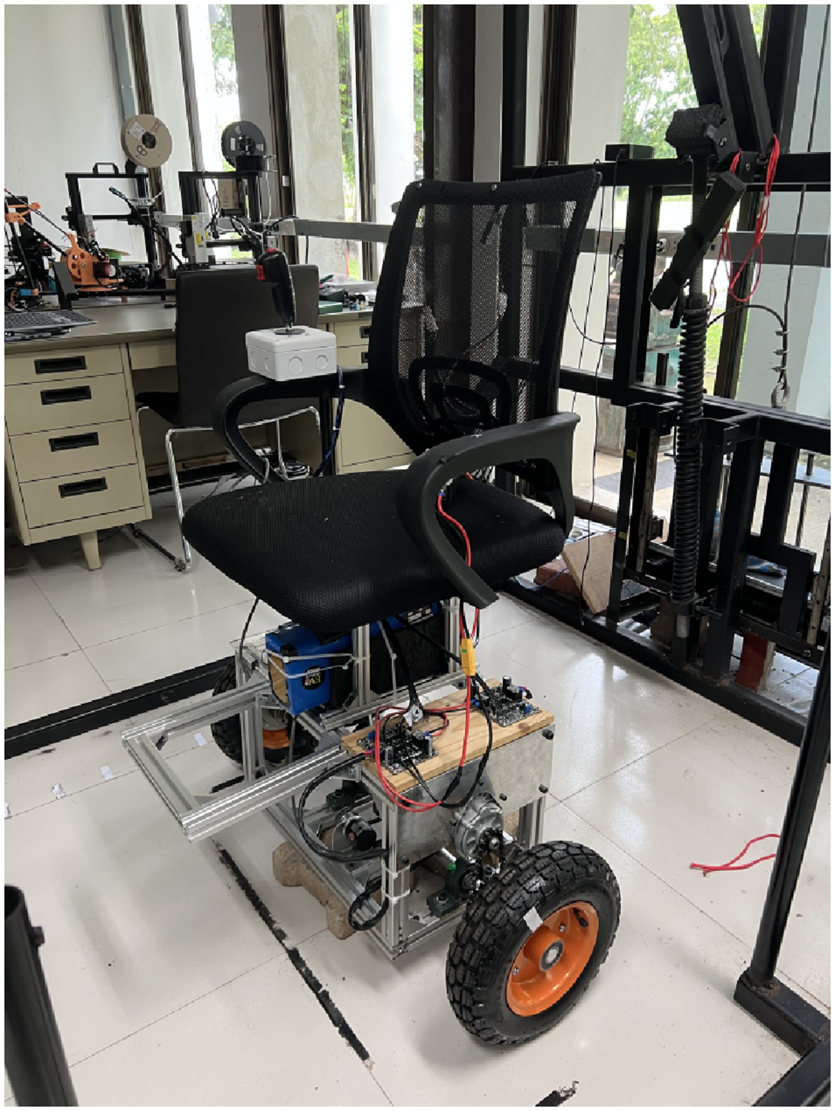
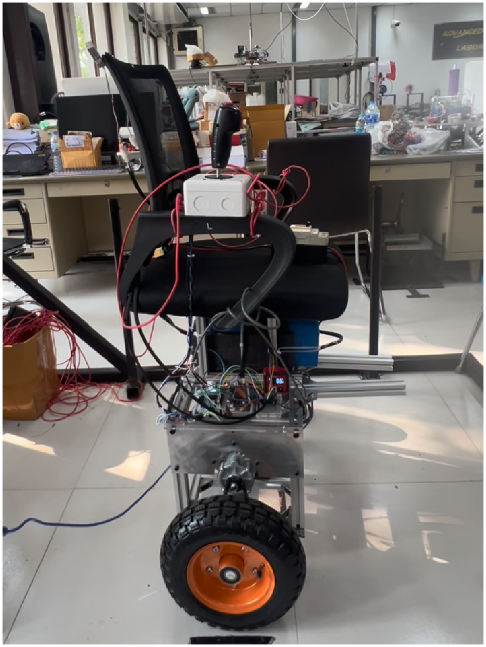
To experimentally validate the proposed control strategies, the LQR and algorithms are implemented on a Segway-type wheelchair controlled by STM32 microcontroller (Figure 8). This hardware implementation bridges the gap between theory and practice by exposing the controllers to real-world uncertainties—specifically sensor noise, actuator bandwidth limits, and unmodeled disturbances—that are often simplified or neglected in simulation environments.
The developed Segway-type wheelchair used as the experimental platform.
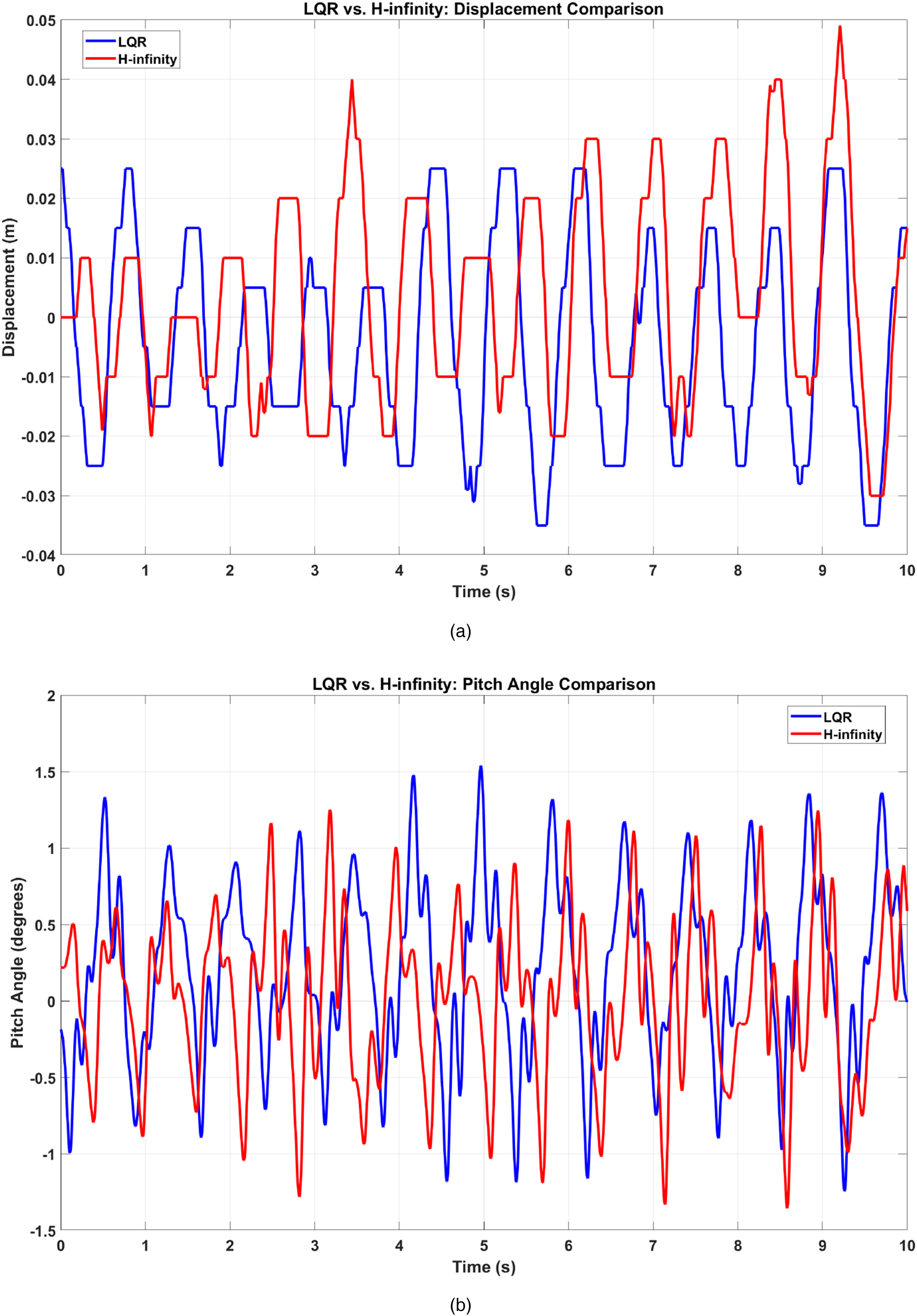
To evaluate the controllers’ performance in a physical environment, the wheelchair’s state variables are measured by an onboard inertial measurement unit (IMU) and wheel encoders. The IMU directly measures the pitch angle and pitch angular velocity, while the encoders track wheel rotation to determine the wheelchair’s position. These real-time data streams provide the necessary feedback for closed-loop control. The first experiment is conducted to test the stationary balancing capability. The experimental results, presented in Figures 9 and 10, confirm that the system behavior is consistent with the simulation trends. Both controllers successfully balance the physical wheelchair.
Experimental comparison of LQR and H-infinity controller during the stationary balancing task. (a) Displacement vs. time and (b) pitch angle vs. time.
Stationary balancing test setup.
In this stationary test, external uncertainties are minimal. However, the pitch angle response (Figure 9(b)) indicates that the controller provides superior pitch regulation, maintaining a tighter steady-state error compared to the LQR. This performance is attributed to the higher control bandwidth of the design; it generates more aggressive corrective torques to overcome small-scale unmodeled nonlinearities, such as actuator dead-zone and static friction, which the linear LQR struggles to compensate for.
However, this aggressive stabilization introduces a compromise in the translational movement. As observed in Figure 9(a), the controller exhibits larger positional oscillations. This behavior exemplifies the fundamental trade-off of robustness: while the LQR operates as an optimal controller excelling in nominal precision within an idealized environment, the controller sacrifices this nominal optimality to guarantee stability against model uncertainty. Consequently, the increased positional oscillation observed in the experiment is the necessary cost for ensuring the system does not fail when facing real-world parameters and disturbances.
Robustness to parametric uncertainty
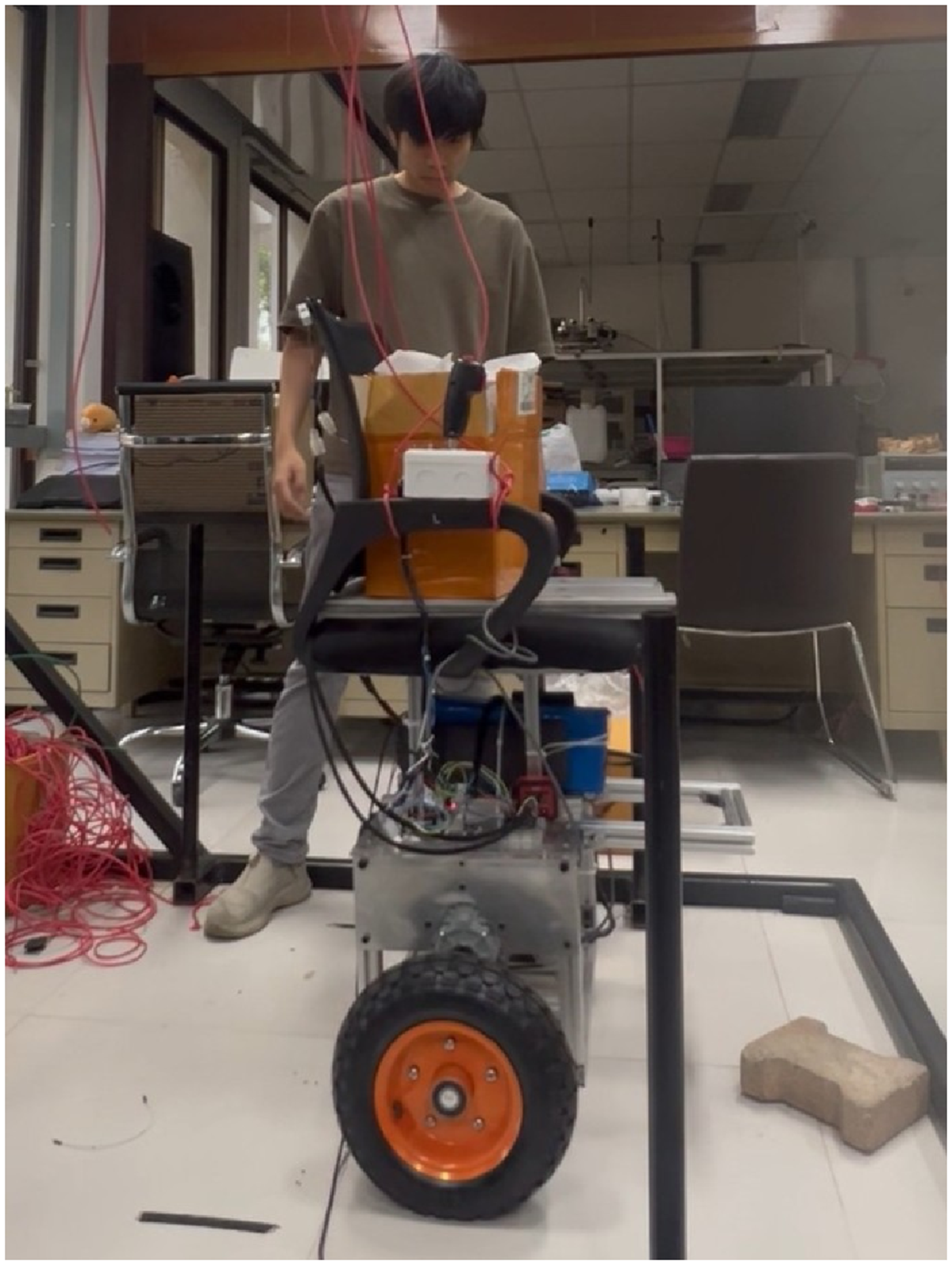
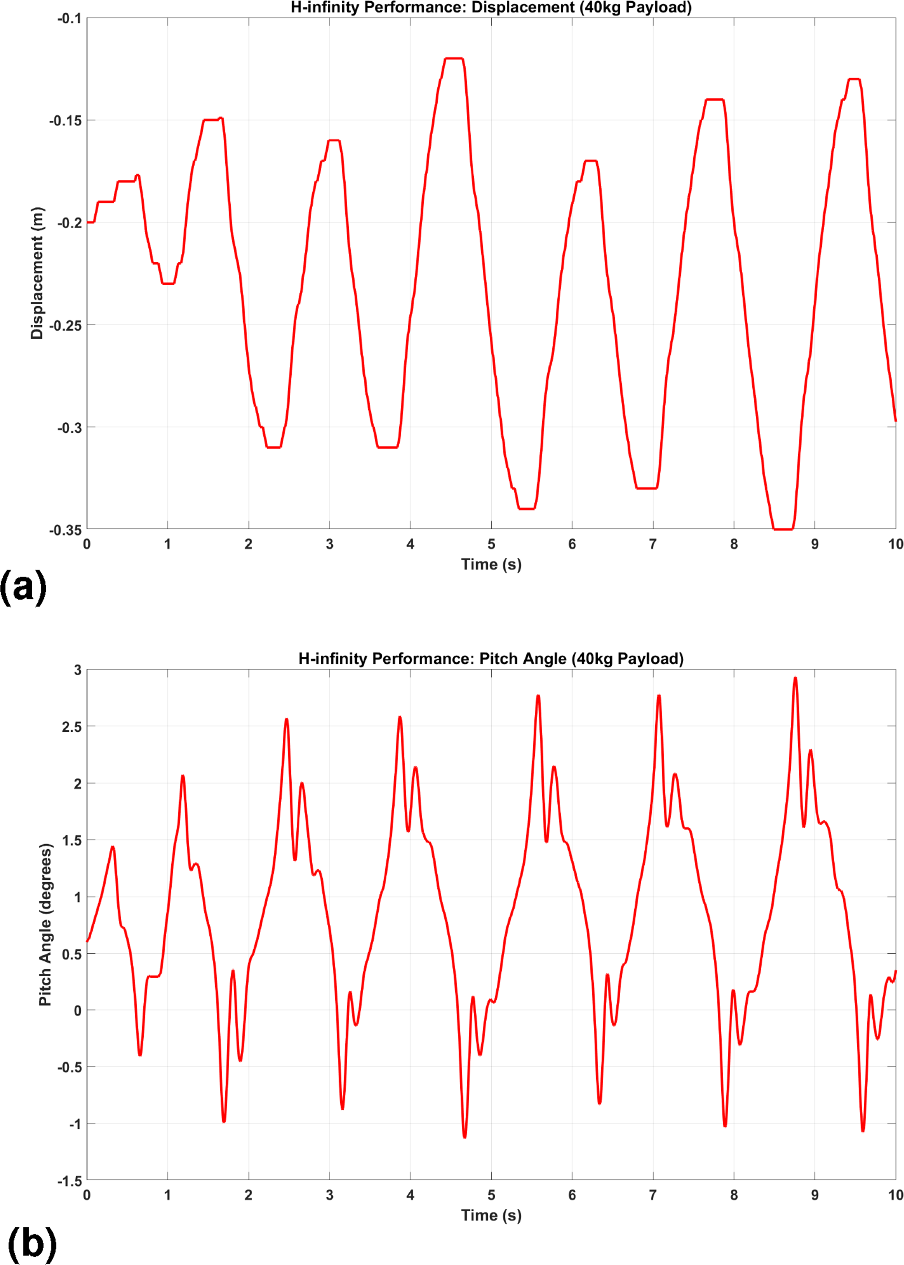
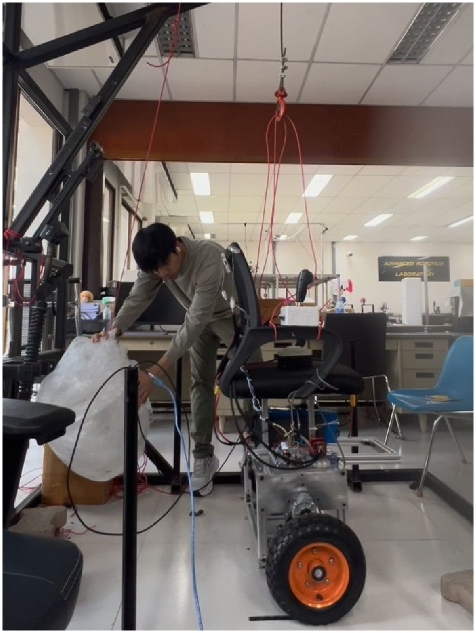
To evaluate the controllers’ robustness to structural variations, an experiment is conducted with significantly altered physical parameters. An additional payload of 40 kg is attached to the chassis, as depicted in Figure 11. This modification significantly increases the total mass and pitch inertia while shifting the center of gravity—a critical perturbation for the balancing dynamics. A stationary balancing task is then conducted to assess the impact of these parametric changes on closed-loop stability.
Robustness test setup with an attached 40 kg mass.
Despite these drastic variations, the robust controller maintains stable performance. The wheelchair’s pitch angle, presented in Figure 12(b), remains regulated within a bounded envelope, confirming the preservation of stability margins. To accomplish this, the controller utilizes active dynamic compensation, as observed in the positional response (Figure 12(a)), autonomously adjusting the wheelchair’s displacement to counterbalance the gravitational moment induced by the added payload.
Experimental result of the H-infinity controller under parameter variations (40 kg mass). The controller maintains stability. (a) Position response under 40 kg mass and (b) pitch angle under 40 kg mass.
In contrast, the LQR fails to stabilize the system under this heavy load. Upon the introduction of the added mass, the system states rapidly diverge, resulting in a complete loss of balance. This failure occurs because the additional payload fundamentally alters the plant dynamics—specifically increasing the pitch inertia and shifting the vertical center of mass. Since the LQR control law is static and optimized strictly for the nominal inertial parameters, it lacks the requisite gain margins to compensate for these severe physical changes. This result definitively demonstrates the sensitivity of the LQR when operating outside its design envelope and highlights the superior robustness of the controller.
Disturbance rejection
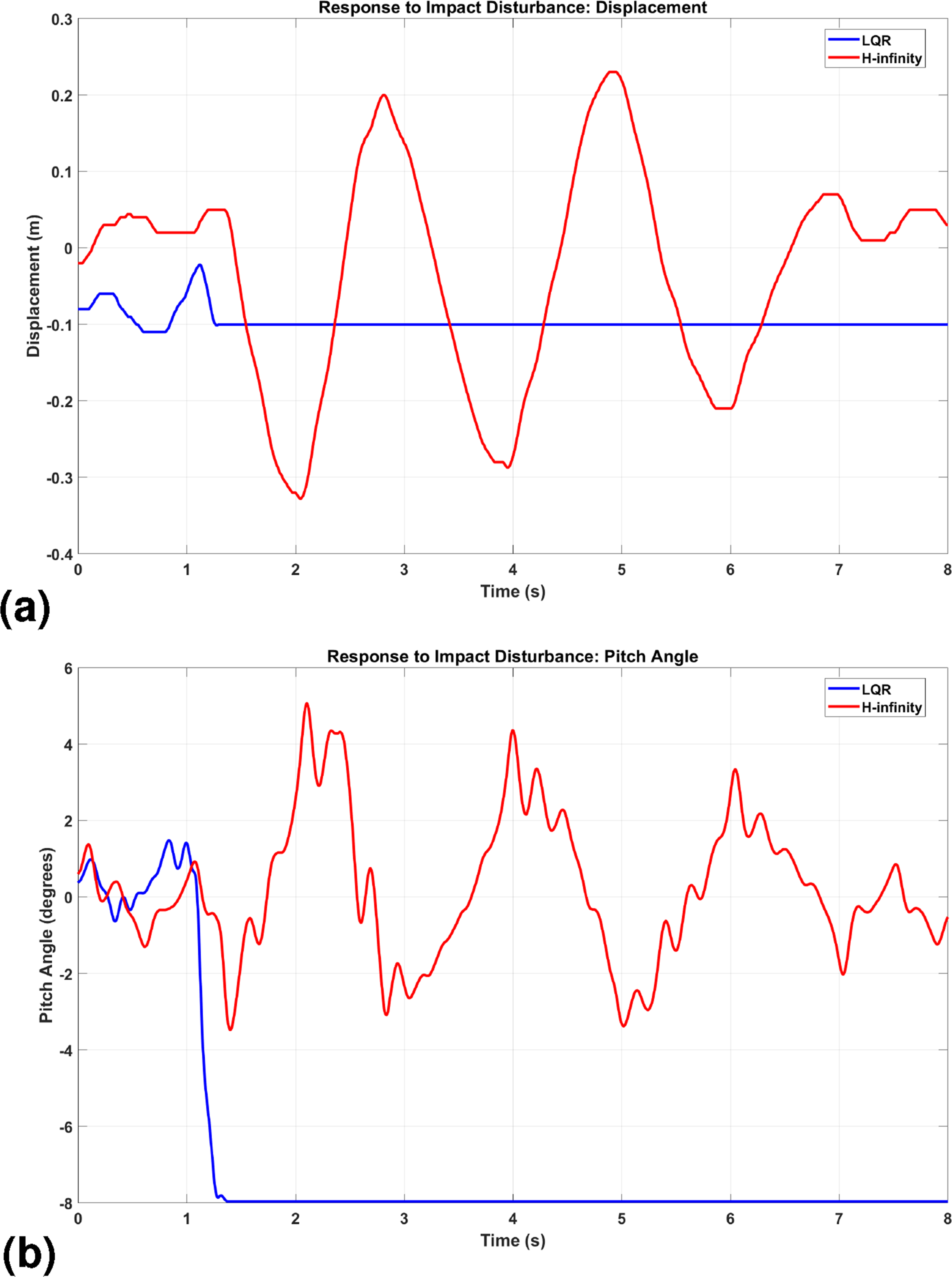
To evaluate the disturbance rejection capabilities, an impulsive force is applied to the wheelchair’s chassis. The disturbance is generated using a pendulum-based impact mechanism, where a 5-kg mass is released from a fixed height to strike the upper chassis, as shown in Figure 13.
Impact disturbance test setup.
This test simulates a high-energy impulsive disturbance, analogous to an accidental collision. The comparative performance of the LQR and the controller is presented in Figure 14.
Experimental result to an impulse disturbance. The controller successfully recovers, while the LQR controller fails. (a) Position vs. time and (b) pitch angle vs. time.
The results provide definitive evidence of the controller’s superior robustness. As observed in Figure 14(b), following the impact at approximately s, the LQR pitch angle immediately diverges, resulting in a complete loss of stability (fall). In contrast, the controller effectively rejects the external shock, attenuating the transient oscillation and recovering the upright equilibrium within a few seconds. This stark contrast highlights the LQR’s inability to handle high-frequency unmodeled dynamics excited by the impact, whereas the loop-shaping of the controller ensures sufficient phase margin to maintain stability.
Conclusion
This study presented the design, simulation, and real-world implementation of a robust controller for a human-scale Segway-type wheelchair. A mathematical model was derived to synthesize both an optimal LQR and a robust controller, with the latter explicitly designed to tolerate model uncertainties and external disturbances.
Comparative simulations revealed a fundamental design trade-off. While the LQR achieved superior tracking performance under nominal conditions, the controller demonstrated decisive advantages in robust stability when subjected to severe parameter mismatches and actuator saturation.
These theoretical findings were rigorously validated on an STM32-based experimental platform. The robustness of the proposed control strategy was evaluated under critical scenarios, including substantial parameter variations and high-energy impulse disturbances. Experimental results confirmed that the controller effectively stabilized the system under these adverse conditions, whereas the LQR failed to maintain equilibrium due to its sensitivity to parametric variations. These findings demonstrated that while LQR provided a baseline for nominal optimality, the strategy proved indispensable for ensuring closed-loop stability in practical applications characterized by significant structural uncertainties and environmental perturbations.
Footnotes
ORCID iD
Jirapod Jintasornrom
Funding
The authors disclosed receipt of the following financial support for the research, authorship, and/or publication of this article: This work was supported by the Asian Institute of Technology.
Declaration of conflicting interest
The authors declared no potential conflicts of interest with respect to the research, authorship, and/or publication of this article.
References
1.
GrasserFD’ArrigoAColombiS, et al.JOE: a mobile, inverted pendulum. IEEE Trans Indust Electron2002; 49: 107–114.
2.
QianQWuJWangZ. A novel configuration of two-wheeled self-balancing robot. Tehnicki Vjesnik2017; 24: 459–464.
3.
NikpourMHuangL. Experimental evaluation of a novel stability control system for two-wheeled robotic wheelchairs. Mater Today: Proc2023. DOI: 10.1016/j.matpr.2023.04.691.
4.
ZhangHMohamad NorN. Control strategies for two-wheeled self-balancing robotic systems: a comprehensive review. Robotics2025; 14: Article 101. DOI: 10.3390/robotics14080101.
5.
MihálikMBujnákMŠimákV. Two-wheel electric chassis with automatic balancing. Trans Res Proc2021; 55: 1026–1033.
6.
FramingCEHedingerRIglesiasES, et al.Edubal: an open balancing robot platform for teaching control and system theory. IFAC-PapersOnLine2020; 53: 17168–17173.
7.
ZhangHMohamad NorN. Fractional-order pid control of two-wheeled self-balancing robots via multi-strategy beluga whale optimization. Fractal and Fract2025; 9: Article 619. DOI: 10.3390/fractalfract9100619.
8.
SenguptaIGuptaSDebD, et al.Dynamic stability of an electric monowheel system using lqg-based adaptive control. Appl Sci2021; 11: Article 9766. DOI: 10.3390/app11209766.
9.
MohammedIKNoamanMN. Optimal control approach for robot system using LQG technique. J Européen des Syst Automat2022; 55: 671–677.
10.
PathakKFranchJAgrawalS. Velocity and position control of a wheeled inverted pendulum by partial feedback linearization. IEEE Trans Robot2005; 21: 505–513.
11.
ZhangCLiuTSongS, et al.Dynamic wheeled motion control of wheel-biped transformable robots. Biom Intell Robot2022; 2: 100027.
12.
NameraLFJinGGSoG, et al.Tracking control of a two-wheeled mobile robot using integral sliding mode control and a linear quadratic regulator. Appl Sci2026; 16: Article 111. DOI: 10.3390/app16010111.
13.
ZhangHMohamad NorNUmarSNH. Modified dual hierarchical terminal sliding mode control design for two-wheeled self-balancing robot. Electronics2025; 14: Article 111. DOI: 10.3390/electronics14132692.
14.
SevekariPTamhaneBKurodeS. Robust control for stable and safe performance of a two wheeled human transporter. IFAC-PapersOnLine2020; 53: 616–621.
15.
YoungKUtkinVOzgunerU. A control engineer’s guide to sliding mode control. IEEE Trans Control Syst Technol1999; 7: 328–342.
16.
GandarillaIMontoya-CháirezJSantibáñezV, et al.Trajectory tracking control of a self-balancing robot via adaptive neural networks. Eng Sci Technol2022; 35: 101259.
17.
SafeeaMNetoP. A q-learning approach to the continuous control problem of robot inverted pendulum balancing. Intell Syst Appl2024; 21: 200313.
18.
LiuCQinKXinG, et al.Nonlinear model predictive control for a self-balancing wheelchair. IEEE Access2024; 12: 28938–28949.
19.
DoyleJGloverKKhargonekarP, et al.State space solution to standard h2 and control problem. Automat Control IEEE Trans1989; 34: 831–847.
20.
GahinetPApkarianP. A linear matrix inequality approach to control. Int J Robust Nonlinear Control1994; 4: 421–448.
21.
HuiNGuoYHanX, et al.Robust h-infinity dual cascade mpc-based attitude control study of a quadcopter UAV. Actuators2024; 13: Article 392. DOI: 10.3390/act13100392.
22.
YenenehKMamoTWalleM, et al.Robust control design for improving handling and ride comfort in semi-active suspension systems. Int J Automot Mech Eng2024; 21: 11542–11553.
23.
BraunPBhardwajABrentariM, et al.Static anti-windup with shifted equilibria applied to a Segway-like vehicle. Automatica2024; 169: 111830.
24.
FrancoEAstolfiABaenaF. Robust balancing control of flexible inverted-pendulum systems. Mech Mach Theory2018; 130: 539–551.
25.
XinGJinBLiuC, et al.A unified control framework for self-balancing robots: addressing model variations in wheel-legged platforms and human-carrying wheelchairs. Sensors2025; 25: Article 7144. DOI: 10.3390/s25237144.
26.
YanCLiX. Research on stability control system of two-wheel heavy-load self-balancing vehicles in complex terrain. Appl Sci2024; 14: Article 7682. DOI: 10.3390/app14177682.
27.
SpongMWHutchinsonSVidyasagarM. Robot Modeling and Control. 2nd ed.Hoboken, NJ: John Wiley & Sons Inc., 2020.
28.
SkogestadSPostlethwaiteI. Multivariable Feedback Control: Analysis and Design. 2nd ed.New York: John Wiley & Sons, 2005.
29.
ZhouKDoyleJC. Essentials of Robust Control. Upper Saddle River, NJ: Prentice Hall, 1998.
30.
FreudenbergJLoozeD. Right half plane poles and zeros and design tradeoffs in feedback systems. IEEE Trans Automat Control1985; 30: 555–565.
31.
SteinG. Respect the unstable. IEEE Control Syst Mag2003; 23: 12–25.
32.
Austin HughesBD. Electric Motors and Drives: Fundamentals, Types and Applications. 5th ed.Oxford: Newnes, 2019.
33.
HuTLinZ. Control Systems with Actuator Saturation: Analysis and Design. Boston, MA: Birkhäuser, 2000.