
Abstract
This paper presents an improved S-curve motion profile to address vibration issues in industrial robots. While numerous studies have optimized motion commands based on the S-curve feedrate profile for vibration suppression, their performance in damped systems has often been suboptimal. To this end, the proposed profile integrates an improved S-curve feedrate motion with local input shaping to accelerate vibration attenuation. The design method is also introduced to minimize its total motion time. Compared with the optimized S-curve, and the time-optimal smooth S-curve, the proposed method based on the improved S-curve possesses superior vibration suppression capability. Furthermore, the improved S-curve achieves this with less time delay than the optimized smooth S-curve. Experimental validations on a serial industrial robot and a gantry platform confirm the practical effectiveness of the proposed motion profile in reducing vibrations, supporting its applicability in robotic systems.
Introduction
Vibrations induced by high-speed robotic motion present a major challenge in industrial applications, particularly in assembly processes that demand high precision and repeatability. These vibrations can substantially compromise production efficiency. Current vibration suppression techniques for robots are broadly categorized into active control and passive suppression. Active control methods, the more prevalent approach in industrial settings, primarily encompass closed-loop feedback control and trajectory planning techniques. Closed-loop feedback control employs sensors to monitor the robot's motion and vibration states, relying on a carefully designed controller to rapidly attenuate vibrations—an approach that typically depends on high-precision sensors.1–6 In contrast, trajectory planning-based vibration suppression provides inherent flexibility as it requires no structural modifications to the robot and can be readily adapted to different motion systems, resulting in broader applicability.7–14
In industrial robot control systems, trapezoidal and S-curve motion profiles are commonly used to execute movement commands from the controller.15,16 The trapezoidal profile, characterized by discontinuous acceleration, generates motion impacts that induce significant vibrations in the mechanical system. 17 In contrast, the S-curve motion profile effectively mitigates vibration due to its smoother kinematic characteristics.18,19 This profile is defined by a finite, step-like jerk (the rate of acceleration change), resulting in a velocity profile that smoothly integrates linear and parabolic segments.7,20
Extensive research has been conducted on optimizing the S-curve motion profile, particularly for high-speed and high-precision applications.6,17,21 Despite its demonstrated effectiveness in vibration suppression, the direct application of a standard S-curve to different motion systems often fails to fully eliminate residual vibration.11,21–23 Traditional trajectory optimization research typically involves analyzing robotic system dynamics. For instance, studies24–26 have examined the characteristics of symmetric and asymmetric S-curve profiles for undamped systems in the Laplace domain, achieving optimization through the pole-zero cancellation principle to minimize residual vibration. Notably, a comprehensive investigation by 17 extended this work to damped systems, proposing a design technique that minimizes residual vibration while ensuring the shortest motion time via time-domain analysis. More recently, research has explored computational intelligence algorithms, such as using genetic algorithms 27 or particle swarm optimization28,29 to optimize robotic joint trajectories. Furthermore, reference 30 introduced a heuristic algorithm that generates motion profiles to effectively suppress residual vibration without increasing the motion time.
Input shaping is an optimization technique that modifies motion profiles to theoretically eliminate residual vibration.31–34 A prominent implementation of this technique is the Zero Vibration (ZV) shaper, 12 which operates by canceling the poles of the vibrational system with its zeros, thereby significantly reducing residual vibration upon motion completion. However, this method introduces a significant limitation: an inevitable time delay.12,13 Applying the ZV shaper to an S-curve produces a customized motion profile for a specific vibrational system, effectively eliminating residual vibration. 35 Reference 13 combined S-curve profiling with input shaping for vibration suppression, proposing the optimal S-curve, robust ZV shaper, and dynamic ZV shaper. Furthermore, reference 36 provided a detailed analysis for designing a minimum-time motion profile based on the vibration suppression effects of the S-curve and ZV shaper, proposing both embedded and heuristic methods to achieve this time-optimal design.
This paper analyzes the mechanism of residual vibration arising from the application of S-curve motion profiles in robotic systems. The analysis reveals that in damped vibration systems, optimizing the S-curve alone is insufficient to completely eliminate residual vibration. To address this limitation, an improved S-curve is proposed, which integrates an optimized S-curve with local input shaping techniques. This hybrid approach achieves superior residual vibration suppression compared to both the optimized S-curve and the optimized smooth S-curve. Unlike global input shaping methods that modify the entire motion profile, the proposed technique applies input shaping only to specific segments of the S-curve, thereby effectively suppressing vibration without introducing additional time delay. Experimental results validate the enhanced vibration suppression performance of the proposed improved S-curve motion profile.
The main contributions of this work are summarized as follows:
An improved S-curve motion profile is proposed by integrating the optimal S-curve with local input shaping. A corresponding design method is developed to minimize the total motion time of the proposed profile. The improved S-curve demonstrates superior vibration suppression performance compared to both the optimized S-curve and the optimized smooth S-curve. Experimental results on a six-axis industrial robot and a gantry platform validate the effectiveness of the proposed motion profile in suppressing vibrations.
Vibration system and S-curve motion profile
Vibration model of single flexible joint
The motion of robots is frequently governed by intricate and highly complex dynamic systems, in which vibrations arising during their movement originate from various sources. Among these, the effect of flexible joints emerges as a particularly notable factor. To facilitate this analysis, we simplify the dynamic system of the flexible joints of a robot into a single-degree-of-freedom spring-damping vibration system.37–39
The robotic system's flexible joint, depicted in Figure 1, can be conceptualized as a linear dynamic system. It consists of a motor rotor connected to the following link through a spring with an elastic coefficient k and a linear damper with a damping coefficient c. The rotational inertia of this link is denoted as I. The system's input is the rotational angle of the joint rotor, designated as x, while the output is the relative displacement between the joint link and the rotor, denoted as y. This simplified model of the system is formalized by the subsequent differential equation:

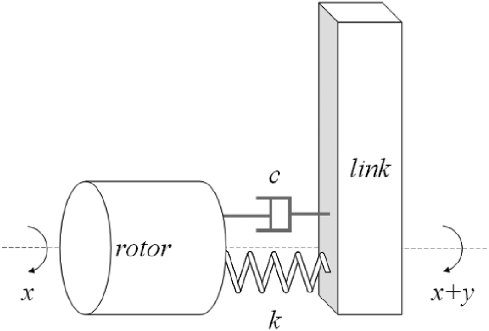
Simplified model of robot flexible joint.
In the Laplace domain, the dynamic relationship between the rotor and the connected link is as follows:
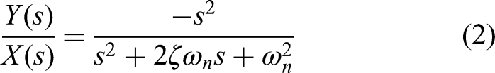
This model enables a comprehensive characterization of the effects of various motion profiles on system vibrations, where
Vibration model of the end effector of serial robots
According to the vibration model of single flexible joint, let the amplitude of vibration generated by joint i be
As shown in Figure 2, the three-dimensional vector
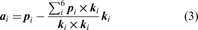

Joint vibration acts on the ends.
The vibration vector
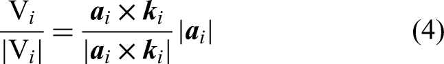
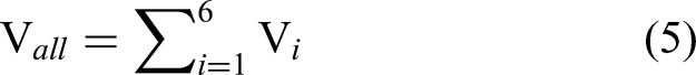
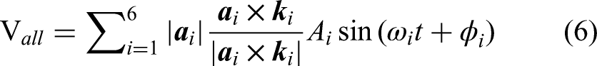
Thus, the resultant vibration at the robot end-effector from all joints is:
Considering the superposition or cancellation of vibrations resulting from the components of joint vibrations acting on the robot end-effector in the same direction. Assuming that the vibration model of each joint conforms to the flexible joint vibration model described in this section, and the vibration signal generated by a joint takes the form of a trigonometric function, let the vibration of joint i be
Generation of the S-curve motion profile
The seven-segment S-curve profile, as shown in Figure 3, encompassing all segments of motion, fully embodying the S-curve. This trajectory includes distinct segments: acceleration-up, constant acceleration, acceleration-down, constant velocity, deceleration-up, constant deceleration, and deceleration-down.
20
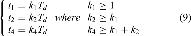
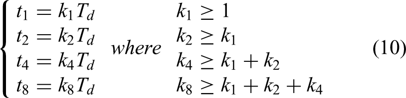
Due to the inherent symmetry of the S-curve, it can be described using three primary time parameters:

S-curve motion profile.
When the jerk of the S-curve transitions from being discontinuous to linear, the motion profile becomes a smooth S-curve, as shown in Figure 4. In this type of profile, the acceleration varies smoothly, ensuring that its first derivative is continuous and reducing shock and vibration to the motion system effectively.

Smooth S-curve motion profile.
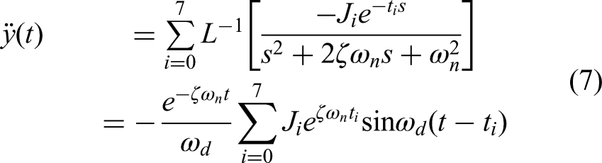
The vibrational response of the robotic flexible joint vibration system to the application of S-curve is as follows:
Improved S-curve motion profile
Optimized S-curve and smooth S-curve motion profile
Reference
17
introduces an optimization method aimed at improving vibration suppression in trapezoidal profile, S-curve profile, and higher-order polynomial profiles, by adjusting the durations of each segment. This optimization technique results in the generation of an optimized S-curve motion profile. This profile is designed not only effectively minimize vibrations but also ensure a rapid completion of motion. As a result, the residual vibration magnitude of the system at time
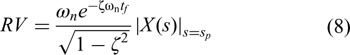
At moment
In the case of the smooth S-curve, it is also crucial to minimize
The physical explanation of vibration suppression through this optimization can be elucidated as follows: Each segment of the S-curve should be carefully designed to ensure its duration is an integer multiple of the resonance period of the vibration system to achieve optimal vibration suppression. This strategic adjustment ensures that the vibration response induced by each jerk step change is effectively counteracted by the subsequent jerk change of equivalent magnitude but opposite direction, thereby leading to minimal residual vibration. In a system with damping, the vibration induced by the jerk change gradually diminishes because of damping effects. As a result, the amplitude decreases in comparison to the vibration induced by the subsequent jerk change. Consequently, even after the mutual cancellation of vibration responses, residual vibrations may still persist. Therefore, the primary achievement of the optimized S-curve lies in its efficacy in eliminating residual vibrations in undamped systems. To enhance the effectiveness in damped systems, this article proposes an improved S-curve that integrates the optimal S-curve with local input shaping to suppress vibrations and achieve complete elimination of residual vibrations.
Improved S-curve motion profile
In comparison to the optimized S-curve motion profile, the improved S-curve motion profile incorporates four additional supplementary segments. These supplementary segments are strategically introduced at specific times (

The improved S-curve motion profile.
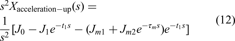
The acceleration characteristics of the acceleration-up segment serve as a typical case study, as the following motion segments show similar acceleration change patterns in different directions. The acceleration profile of this segment can be succinctly depicted as follows:
To explain the principle of vibration suppression, the jerk change from
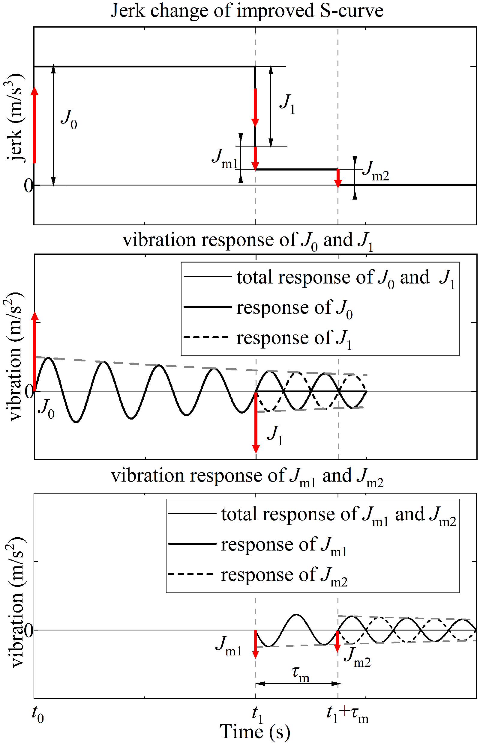
The response of jerk changes in the acceleration-up segment of the improved S-curve motion profile and the system vibration.
Following the adjustment of
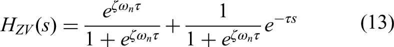
ZV input shaper splits one input impulse into two to produce vibration responses that cancel each other out, effectively eliminating residual vibration. The design of the ZV shaper is dependent on the parameters of the vibration system, specifically the natural frequency
In the supplementary segment, two impulses occur: one at time
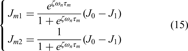
The delay time

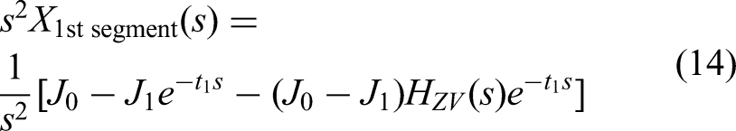
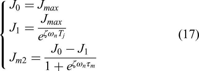
In conclusion, the jerks for the acceleration-up segment and the supplementary segment of an S-curve motion profile can be determined as shown in (17), if the time
The time
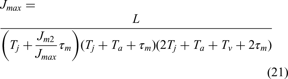
The minimized motion complete time of improved S-curve
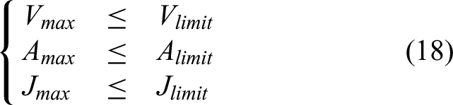
To achieve motion planning that enables high-speed movement with vibration suppression, it is essential to minimize the motion completion time of the improved S-curve. The design principle behind reducing the time for the S-curve motion profile involves extending the duration of maintaining maximum speed throughout the motion while minimizing the time spent on acceleration variations. During the motion of the improved S-curve, there are constraints on the maximum speed
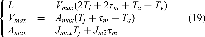
The improved S-curve motion exhibits symmetry in the variations of jerk, acceleration, and speed, enabling a detailed analysis of maximum velocity, acceleration, and total displacement during the motion, showing in (19). For example, the maximum velocity can be determined by integrating the acceleration curve over time, which simplifies to calculating the area of a rectangle with side lengths
In order to achieve minimized motion completion time while complying with motion constraints in the improved S-curve motion profile, the optimal choice for the supplementary segment time is considered crucial. A shorter supplementary segment time contributes significantly to minimizing the overall motion completion time. However, it is essential for supplementary segment time to also satisfy the minimal vibration condition as outlined in (16). Therefore, the recommended optimal supplementary segment time is identified as half of the resonance period, with
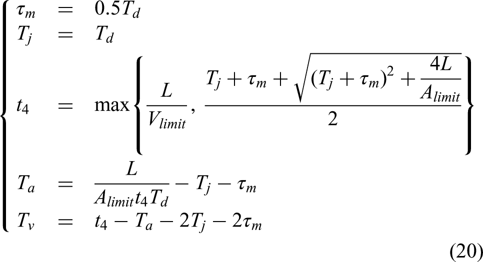
The second term in the expression for
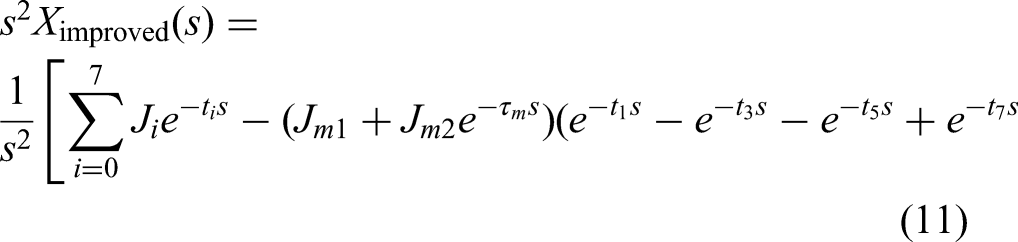
To ensure that the improved S-curve reaches the desired displacement at the end of its motion, one can leverage its motion characteristics to compute the overall displacement, involving solely the jerk and time parameters. Consequently, the jerk for the improved S-curve can be determined as follows:
Simulation and experiments
Simulation
A single-degree-of-freedom (DOF) vibration simulation system was developed to evaluate the vibration characteristics induced by different trajectory-planning motion curves. The system, configured with parameters
Three distinct trajectory profiles—the unoptimized S-curve, the optimized S-curve, and the improved S-curve—were designed and implemented. These profiles were generated using specific design parameters defined by
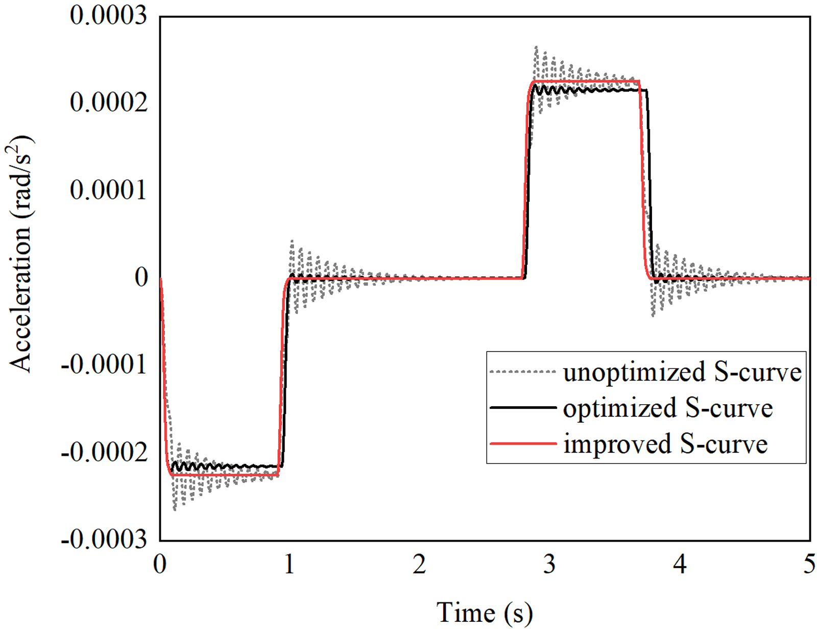
Simulation results of vibration suppression.
Both the optimized and improved S-curves exhibit significantly lower vibration response amplitudes than the unoptimized S-curve, demonstrating superior performance in residual vibration suppression and motion time efficiency. Quantitative analysis confirms that the optimized S-curve reduces residual vibration to 35.45% of the unoptimized S-curve's level. The improved S-curve achieves even more pronounced suppression, capable of entirely eliminating residual vibration under ideal conditions. Simulations corroborate these findings: whereas the unoptimized and optimized S-curves exhibit residual vibration at motion completion, the improved S-curve—through jerk adjustment incorporating damping characteristics and local input shaping—successfully negates all residual vibration, yielding a highly stable and smooth motion profile. Crucially, this enhanced vibration suppression is achieved without prolonging the total motion time, as the improved S-curve completes the target displacement in the same duration as the other two curves.
Experiments on six-axis industrial robot
Experiment setup
The ZK1400-06 six-axis industrial robot, designed by Zhenkang Technology is utilized in the experiment, which is seamlessly integrated with a Googol robot controller to facilitate motion trajectory planning and direct the robot's movement. This controller efficiently interprets motion feedback data and processes sensor data from a six-axis acceleration sensor, developed by Weizhen Technology, attached to the robot's end to capture acceleration variations. The sensor data, relayed to the computer through the TCP/IP protocol, provides crucial insights into the vibration status of the robot during movement. The controller incorporates motion constraints, target displacement, and vibration system parameters to generate motion trajectories effectively. By employing PID control of position, speed, and current, the robot executes movements precisely aligned with the planned motion profile. Motion feedback information is collected through encoders and current sensors on the robot's joints. This interconnected system allows for accurate monitoring and control of the robot's movements, as illustrated in Figure 8 depicting the experimental setup.

The experimental setup.
Measurement vibration system parameters
The robot was held in a fixed posture and subjected to an impact to excite free vibration. The corresponding vibration signal, measured at the end-effector, is shown in Figure 9.

Free vibration signals of robot.
Systematic collection of vibration data from the experimental robot undergoing free vibration enables the determination of the resonance frequency,
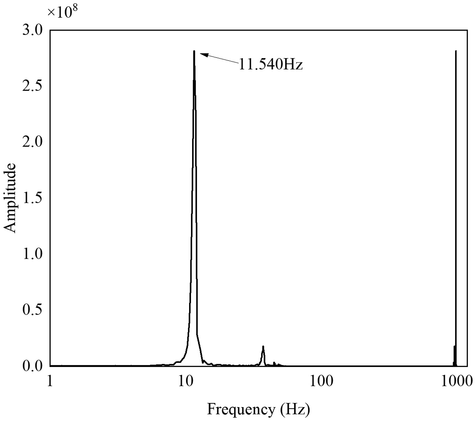
Vibration signal spectrum analysis.
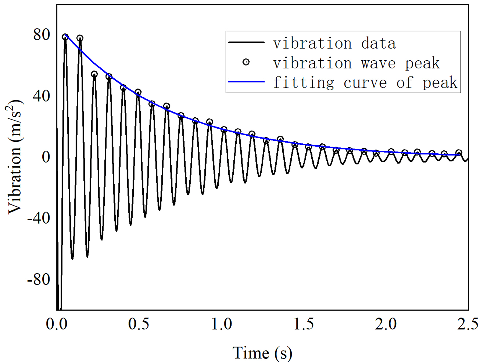
Damping analysis attenuation curve fitting.
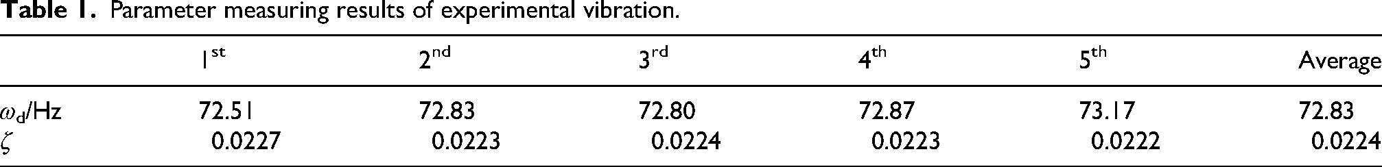
To reduce experimental errors, five sets of experimental data are averaged. The resulting natural frequency and damping values of the system are presented in Table 1.
Parameter measuring results of experimental vibration.
Comparison experiments of motion profiles
The robot controller is utilized to plan and control the motion of the three distinct motion profiles, which are the optimized S-curve, the optimized smooth S-curve, and the improved S-curve. Within specific constraints such as a maximum velocity of Vmax = 80 °/s, the maximum acceleration of Amax = 300 °/s2, and a target displacement of L = 60 °, the minimized motion complete time for each profile is determined, shown in Table 2.
The minimized motion completion time of four motion profiles.

The smooth S-curve, which incorporates multiple motion segments compared to the S-curve, experiences an extended minimum motion completion time when optimized, which is at least
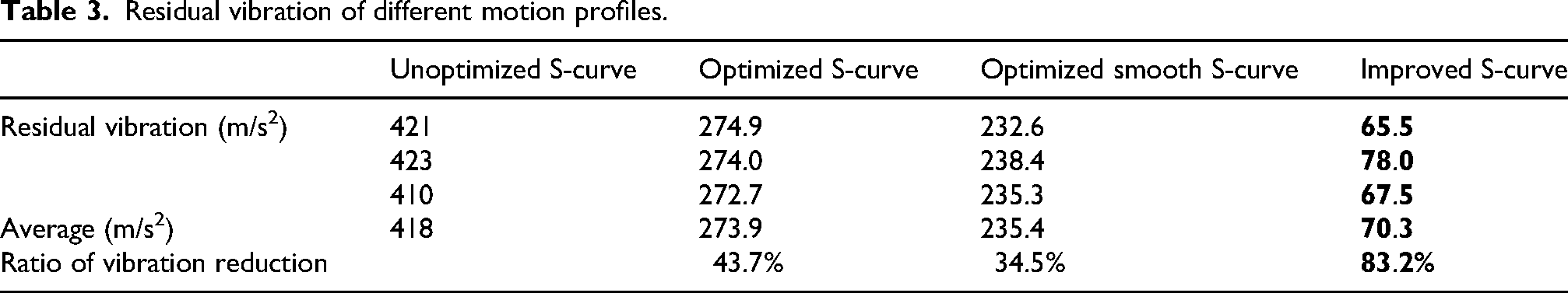
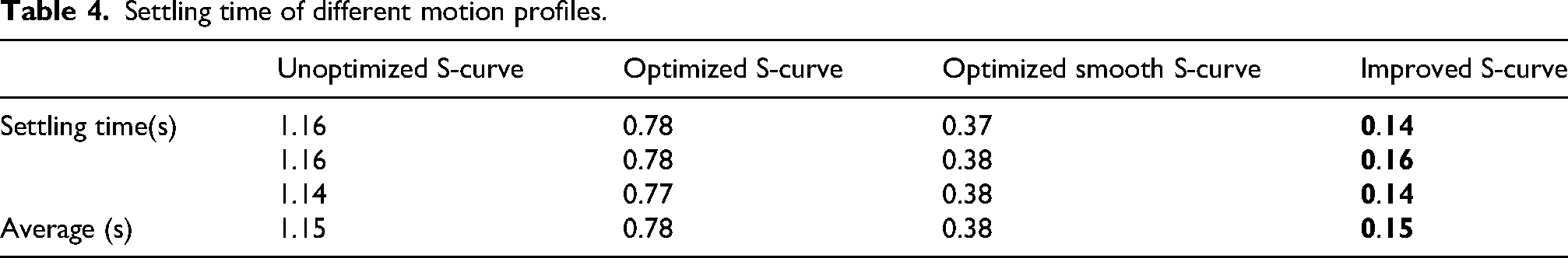
Figure 12 illustrates the vibrational responses of the robot under various motion profiles, showcasing the impact of different optimized profiles on vibration suppression. The improved S-curve stands out for its superior vibration reduction capabilities compared to both the optimized S-curve and optimized smooth S-curve. Specifically, the improved S-curve achieves an 83.2% reduction in vibration amplitude, while the optimized S-curve achieves and the optimized smooth S-curve achieve reductions of 34.5% and 43.7%, respectively, shown in Table 3. To evaluate the settling time of residual vibrations, we introduce the parameter
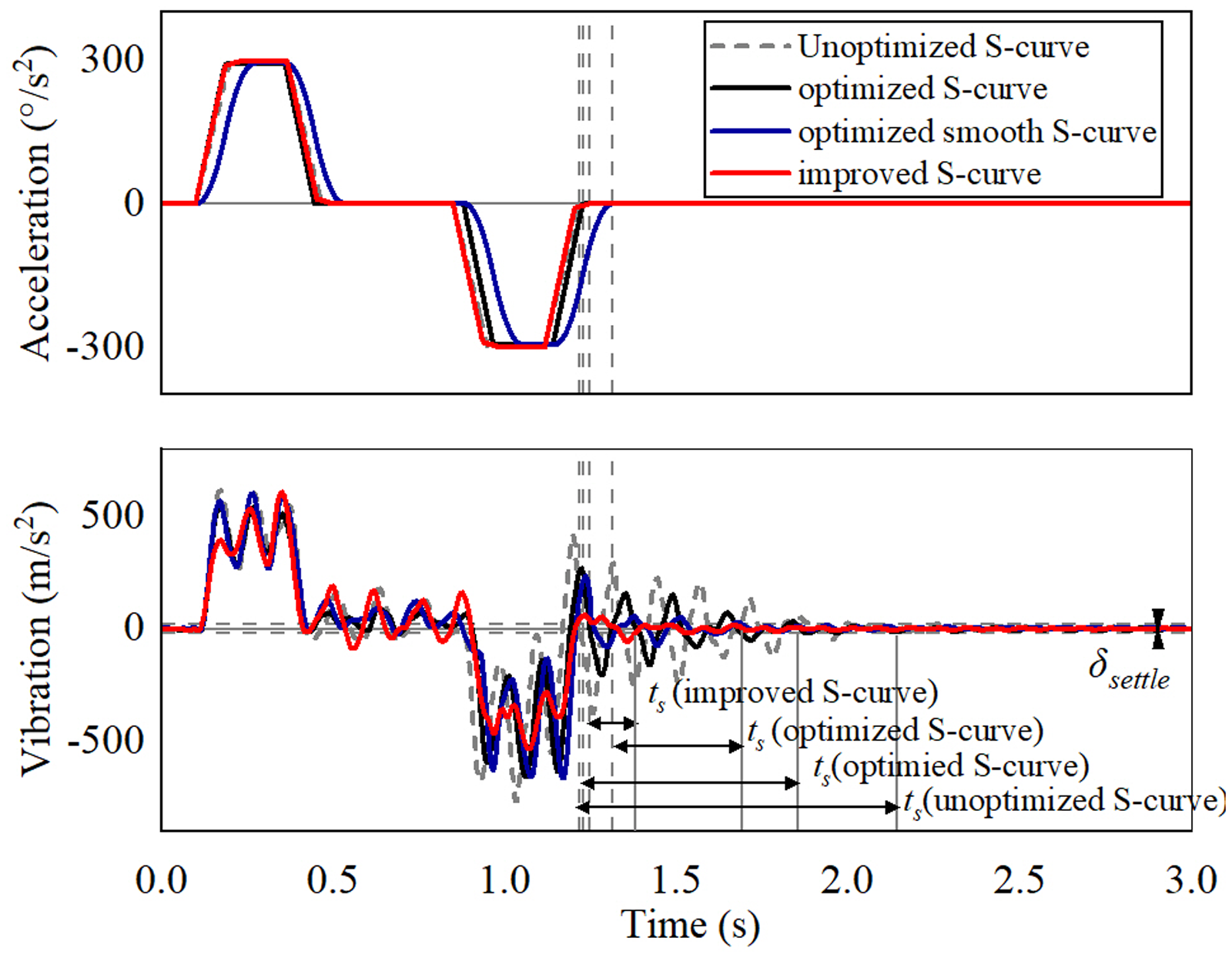
Vibration of the unoptimized S-curve, optimized S-curve, optimized smooth S-curve, and improved S-curve motion profiles.
Residual vibration of different motion profiles.
Settling time of different motion profiles.
The improved S-curve motion profile, with the incorporation of a supplementary segment, displays superior vibration suppression capabilities compared to the optimized S-curve and the optimized smooth S-curve motion profiles. Furthermore, the improved S-curve profile offers reduced complexity in comparison to the optimized smooth S-curve profile, enabling simpler trajectory planning for the controller and decreasing computational requirements. This increased simplicity not only assists in lowering the likelihood of errors during trajectory planning and drive input but also contributes to improved overall performance.
When the pose of a six-axis robot changes, the natural frequency and damping ratio parameters in the model also change. However, when the changes in the robot's pose are minor, the improved S-curve remains effective.
Experiments on gantry platform
Experimental setup
To further validate the universal applicability of the proposed improved S-curve motion profile in suppressing residual vibrations induced by trajectory planning, comparative experiments were conducted on a high-precision gantry motion platform. This platform represents a class of motion systems that require extremely high positioning accuracy and end-effector stability, and its residual vibration characteristics share similar physical origins with industrial robots.
The experimental setup consists of an XY gantry, an controller and a computer, shown as Figure 13. An industrial camera is mounted on the gantry end-effector to monitor the repetitive positioning accuracy when the platform approaches a fixed point, which is directly affected by residual vibrations after motion. Two trajectories are compared: 1) conventional S-curve, and 2) improved S-curve. The platform performs reciprocating point-to-point motion over a distance of 50 mm in both positive and negative directions.
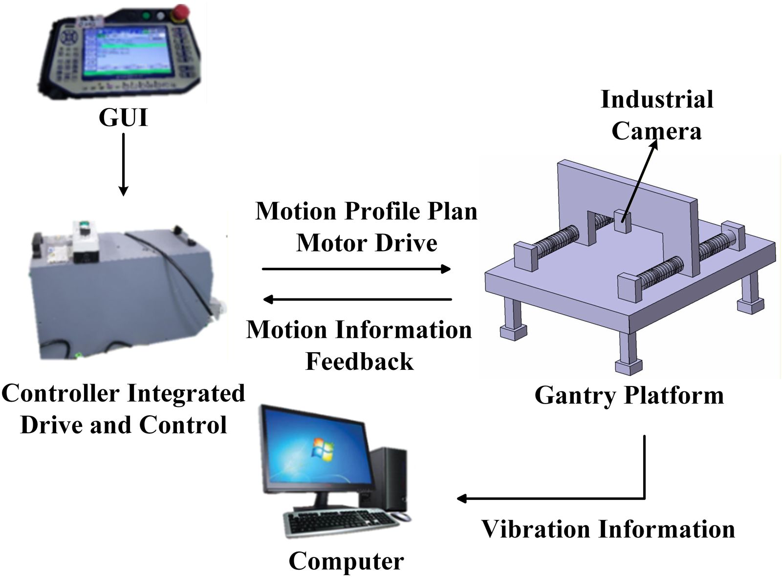
Experiment setup of the gantry platform.
Experimental results
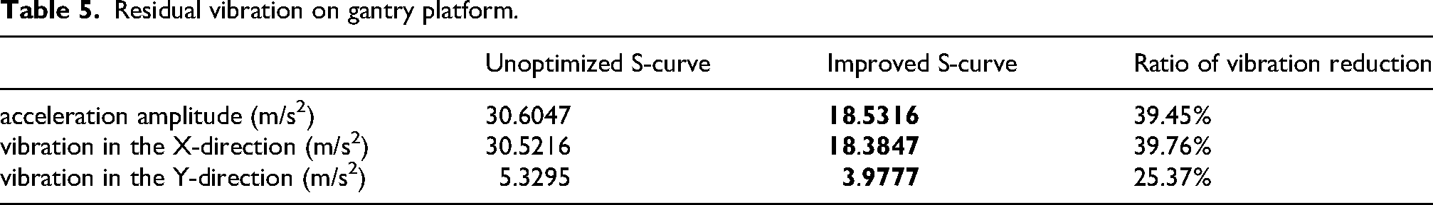
As shown in Figure 14, the vibration responses of the gantry platform under two motion profiles are illustrated. Compared with the conventional S-curve, the improved S-curve demonstrates superior vibration suppression capability. Specifically, the peak acceleration amplitude is reduced by 39.45%, the peak vibration in the X-direction by 39.76%, and the peak vibration in the Y-direction by 25.37%, as presented in Table 5.
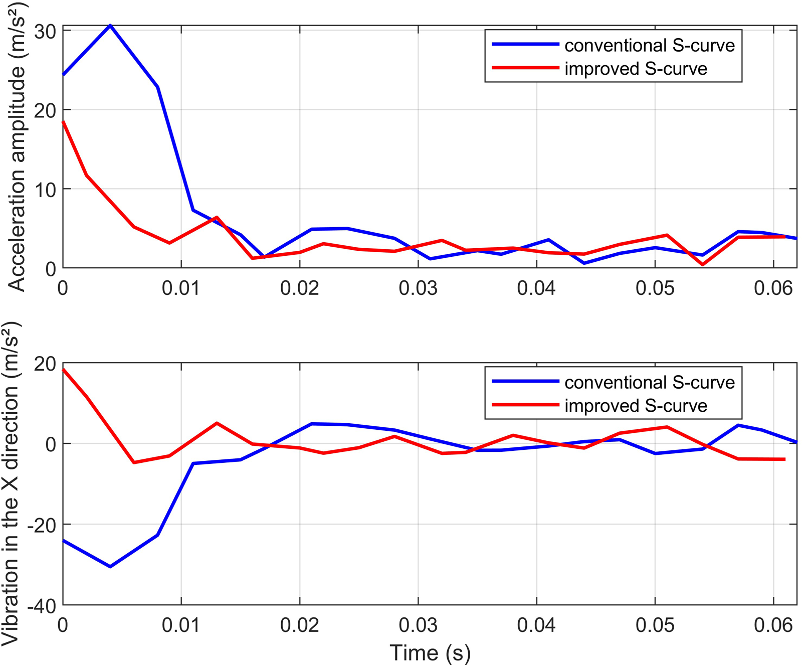
Vibration of the conventional S-curve and improved S-curve motion profiles on gantry platform.
Residual vibration on gantry platform.
These vision-based measurements confirm that the improved S-curve profile significantly enhances positioning stability in gantry platform.
The improved S-curve effectively attenuates residual vibrations excited at the kinematic boundaries of mechanical systems. This property is essential for end-effector contact force control, as illustrated in Figure 15, because it suppresses dynamic disturbances from servo systems and structural resonances at the source. Consequently, the quality of the force sensor's feedback signal is significantly enhanced. This improvement enables the force controller to more accurately identify true contact forces and environmental impedance, thus improving both the stability of contact transients and the accuracy of steady-state force tracking in applications such as precision assembly and constant-force polishing. Ultimately, this method achieves higher-performance compliant control in dynamic interaction tasks.
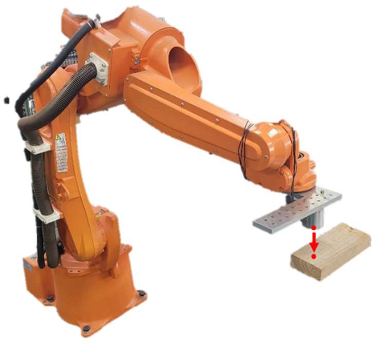
Robot end-effector contact force control.
Conclusions
This study has developed an improved S-curve motion profile by integrating an optimized S-curve with local input shaping techniques, grounded in an analysis of the physical principles governing S-curve-based vibration suppression. An associated design method is also introduced to determine the minimum achievable motion completion time for the proposed profile. The effectiveness of this method was validated through simulations on a single-degree-of-freedom vibration system, experiments with an industrial robot and experiments on a gantry platform. Comparative evaluations against existing S-curve methods demonstrate the superior performance of the proposed approach in simultaneously achieving enhanced vibration suppression and reduced motion time. Collectively, the simulation and experimental results confirm the high efficacy of this trajectory planning method in mitigating vibration issues during high-speed operation of industrial robotic systems and gantry platform.
Future work will focus on extending the proposed method in several directions. A more comprehensive dynamic model that includes multi-mode vibration and configuration-dependent dynamics could be adopted to refine the profile design. Sensitivity analysis with respect to parameter variations (e.g., damping, payload) and integration with adaptive feedback controllers will be investigated to enhance robustness in uncertain environments. Experimental tests on complex multi-axis trajectories and under varying operational conditions will further demonstrate the method's practical utility in advanced industrial applications.
Footnotes
Ethics approval
This work did not require ethics approval.
Consent to participate
Informed consent was obtained from all individual participants included in the study.
Consent for publication
All participants in this study consented to publication.
Funding
This work was supported by National Key Research and Development Program of China (Grant numbers 2022YFB4702100).
National Key Research and Development Program of China (grant number 2022YFB4702100).
Declaration of conflicting interests
The authors declared no potential conflicts of interest with respect to the research, authorship, and/or publication of this article.
Data availability statements
Data in this work cannot be shared openly to protect study participant privacy.