
Abstract
Tendon-driven continuum robots offer exceptional flexibility and slenderness, making them particularly suitable for inspection and maintenance in constrained and unstructured environments as well as robotic surgery. However, their control remains challenging due to nonlinear behavior, limited sensory feedback, and a significant kinematic dissimilarity from existing controllers. These challenges make continuum robots, similarly to endoscopes, their non-robotic counterparts, require a cost- and time-expensive training for users who operate them in such critical environments. This paper addresses this point by designing and implementing a custom, user-friendly control interface for a tendon-driven continuum robot, leveraging principles from both robotics and gaming to enhance intuitiveness and accessibility. After developing a custom graphical user interface, a prototype has been manufactured to evaluate system performance in a dedicated testing environment. Twelve participants have attempted a timed navigation task using the proposed interface, with data collected to assess usability and control accuracy. Results confirmed the feasibility and effectiveness of the system: users were able to navigate the robot through the course with minimal training. Participant feedback is then analyzed to identify meaningful directions for improvement.
Keywords
Introduction
Continuum robots, inspired by biological structures such as snakes, elephant trunks, and plant tendrils, are a class of robotic systems characterized by their slender, continuously deformable, and compliant backbones. Unlike traditional rigid-link robots, continuum robots are capable of smooth, continuous bending along their entire length, which makes them uniquely suited for navigating and manipulating within space-constrained and unstructured environments.1,2 Due to their features, continuum robots have found increasing application across a wide range of fields, including minimally invasive surgery, 3 search and rescue operations,4,5 and industrial inspection.1,2 In particular, their flexibility and adaptability make them ideal for tasks involving the deployment of tools or sensors into deep, tortuous, or confined spaces where conventional robotic arms would be ineffective or unsafe. 6
Among continuum robots, tendon-driven designs are widespread, achieving a good balance between slenderness and performance despite challenges related to bulky actuation units and transmission losses due to tendon friction and elasticity.7–9 Other actuation methods, such as the use of antagonistic pneumatic chambers or pre-curvature (see concentric-tube continuum robots 2 ), either require large onboard space, hindering miniaturization, or cannot scale easily in length. The capability to overcome these limitations makes tendon-driven continuum robots particularly suited to all those applications in which similar systems are already widely adopted: endoscopes are already the reference standard for medical diagnosis, and borescopes for industrial inspection. Both systems are akin to mostly passive continuum manipulators with a tendon-driven tip with a single degree of freedom; this highlights the higher technological readiness of tendon-driven systems when compared to alternative designs.
In tendon-driven continuum robots, multiple tendons are routed along a flexible backbone and anchored at various locations. When a tendon is pulled, it applies force to the compliant backbone, causing the corresponding segment to bend in the direction of the tendon path. Tendon-driven continuum robots can be structured with multiple stacked segments, where each segment is terminated by one or more tendons. 10 To achieve planar bending (one degree of freedom), at least two tendons must be routed on opposite sides of the backbone. This configuration allows for bidirectional bending control. For spatial bending (two degrees of freedom (DOF)), a minimum of three tendons is required, though many implementations use four tendons in antagonistic pairs for increased stability. 2 The tendon routing path significantly influences the robot’s motion capabilities. 11 Tendons can be co-located, meaning that they share the same routing channel but terminate at different segments, or they can be independently routed through dedicated channels.
This unique mechanical design introduces significant challenges in terms of control and remote operation because of its nonlinear behavior and strong kinematic dissimilarity from rigid-link robots. Traditional human–robot interfaces, such as teach pendants or joint-by-joint teleoperation, are often inadequate for intuitively controlling the complex, continuous motion of tendon-driven continuum robots. 12 As a result, custom interfaces have been developed to allow human users to control them effectively.
In past work, 13 researchers have proposed a joystick-based teleoperation system featuring three distinct control schemes designed to offer intuitive and flexible interaction with continuum robots. The robot is operated through a physical user interface consisting of two joysticks and a mode-switching panel, allowing users to manipulate the bending of the robot’s two tendon-driven sections in different ways: the user can control independently the two sections with each joystick, requiring high coordination and training, or couple them together to a single joystick to enable one-handed use but with less dexterity. A “re-centering protocol” allows users to return the robot to a default upright position, simplifying recovery and reset during operation.
In another example, 14 a novel control interface is designed for the teleoperation of tendon-driven continuum robots (TDCRs) for medical purposes. The interface is a custom haptic joystick with four DOF, enabling intuitive and precise control of robot tip orientation and translation. A similar custom design from the Morimoto Lab, 15 called Hapstick, is a soft, flexible haptic joystick that uses fiber jamming to modulate its stiffness and provide feedback to users during teleoperation tasks. Both these examples reduce the kinematic dissimilarity between controller and robot, but require custom manufacturing and intensive user training.
A further example 16 operates a continuum robot with a haptic controller, obtaining force feedback from process sound signals. Controller tip is mapped onto robot tip, offering an intuitive solution for low-mobility motion (1 DOF with feedback) that can hardly be scaled to robots with higher mobility. Another example of a commercial interface for continuum robots uses a double-hat joystick. 17 In both these last cases, commercial controllers simplify the manufacturing process, but user training is still required to get familiar with the specific controller and use case. Further, no user interface study is ever reported in these works, and the usability of the proposed control method is not evaluated.
In this paper, we aim to remove the accessibility barrier for continuum robot teleoperation by creating an intuitive mapping and control strategy for commercial video game controllers. This approach presents several advantages over existing control interfaces, particularly in enhancing user experience and reducing learning curves thanks to the Microsoft Xbox game controller’s ergonomic design, widespread availability, and user familiarity.18–20 Unlike custom-built or specialized haptic joysticks, which often require additional training, the button and joystick layout naturally supports multi-DOF control. The embedded vibration feedback further enhances its transparency. Additionally, the Xbox controller is readily available on the market and is compatible with any PC, making it a convenient and cost-effective choice for implementation.
However, these advantages come with a main challenge, rarely discussed in past studies that mention using game controllers with continuum robots:21,22 the kinematic dissimilarity between the Xbox controller and continuum robot. In the next section, we discuss continuum robot modeling and kinematic spaces, highlighting the different motion variables that can be mapped to the controller and how the difference between the physical behavior of the robot and the joystick complicates this mapping. Then, we present system development, with a continuum robot prototype and GUI design. Finally, we report experimental tests on a mock-up with a survey on user experience.
Robot modeling
System architecture
In this article, we refer to a two-section planar continuum robot as a representative example, following the architecture in Figure 1. By including multiple sections and a linear stage at the base for insertion in the desired workspace, this layout is the simplest one to include the essential motion capabilities of tendon-driven continuum robots. Even though the rest of the article refers to this example, the proposed formulation can be scaled up as discussed later.

Example architecture of tendon-driven continuum robot, with two independent planar sections capable of bending through antagonistic tendon pairs driven each by a motor through a pulley. A third motor transmits linear motion to the system through a rack and pinion mechanism.
The kinematics of continuum robots can be described in four different spaces, as summarized in Figure 2:
Task space is referred mainly to the tip of the robot, and the variables in this case are the Cartesian position ( Configuration space describes the shape of the robot; when using the piecewise constant curvature kinematics (PCCK),
23
it can be defined through the bending and direction angles of consecutive circle of arcs, each describing a section ( Actuation space contains the different tendon displacements ( Motor space is the lowest kinematic layer, describing the angular position (
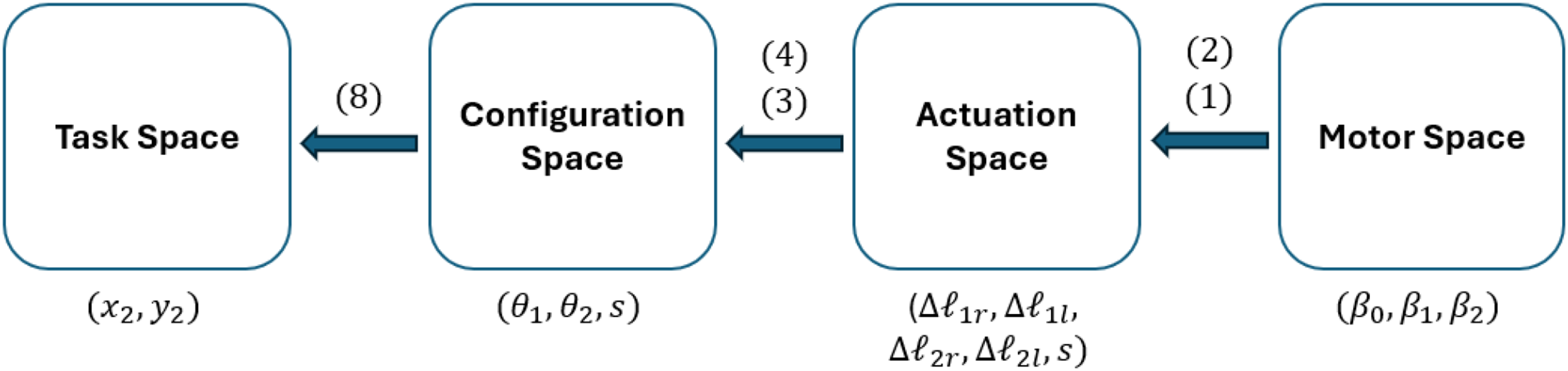
Kinematic spaces in tendon-driven continuum robots.
Kinematics
Motor space to actuation space
Each section of the robot is driven by two antagonistic tendons, for a total of four cables (see nomenclature in Table 1). Each pair of tendons is routed over a single pulley (see Figure 3, resulting in


Kinematic parameters from motor space to actuation space.
Nomenclature.
As elongating one tendon shortens its antagonist by the same amount, we can use a single motor per section to drive the antagonist, cutting the total number of motors in half for the continuum robot.
In addition to bending, the robot can translate vertically by a rack and pinion mechanism (see Figure 3) driven by a third motor, producing a linear displacement
Actuation space to configuration space
To model the robot’s shape, we adopt the PCCK approximation,
2
which represents each section of the backbone as an arc of constant curvature. Although the PCCK model does not account for frictional effects, it captures the essential behavior of a continuum robot and provides a sufficiently accurate framework for understanding and controlling its motion in space. As our example robot operates strictly in a plane, we can neglect the bending direction angle

Kinematic parameters from actuation space to configuration space.
To move from the actuation to the configuration space, the first section is defined as
The same cannot be said for the second section due to the fact that its tendons (
Configuration space to task space
For the first section, the transformation from its base frame (0) to its tip frame (1) is
Similarly, the second section is defined as
Multiplying these transformation matrices relates the robot’s pose 

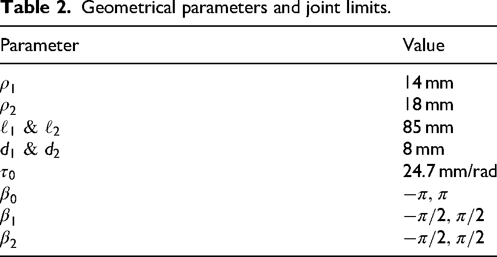
This forward kinematic model allows us to compute the workspace of the system by introducing geometrical parameters and joint limits, thus allowing us to plan for operation. In the proposed example, the geometry in Table 2 has been used to obtain the workspace in Figure 5.

Workspace of an example two-section planar tendon-driven continuum robot.
Geometrical parameters and joint limits.
System development
Digital twin
The first part of the user interface includes a virtual representation of the robot that is automatically updated with real-time motor and sensor data. Thus, the virtual model replicates the continuum backbone geometry in real time as a function of the three motor angles
Figure 6 shows the digital twin in an interactive Python environment, where three interactive sliders, one per motor, can be used to modify

Screenshot of the Python-based digital twin section of the graphical user interface (GUI), showing the backbone curve and tip position in the current configuration. The motor angle sliders on the bottom also allow for direct control of motor variables.
Controller and motor integration
A wired Microsoft Xbox controller has been used for robot control; alternative controllers with universal serial bus (USB) connection can also be employed, with PlayStation and Nintendo Switch Pro controllers, or other third-party alternatives for the main game consoles on the market, allowing for similar button layouts. These controllers benefit from extensive product development and research on ergonomics and accessibility. Having been used by millions of people, they ensure minimal fatigue over prolonged use and ensure user familiarity with their layout and functioning. Finally, they are widely available on the market at a lower cost than custom or specialized joysticks or haptic controllers, as seen in past literature on the topic.
The controller provides main buttons with digital ON/OFF input (A, B, X, Y, LB, RB, Back, Start, Home), two analog joysticks that provide two-axis input on a continuous
Mapping
To intuitively and smoothly control the motors and subsequently the robot itself, a proper mapping of the controls had to be designed for cost-effective, widely diffused gaming controllers to create a control strategy suitable for everyone. The first decision regarded whether to control the system in position or velocity. By mapping position directly to joystick value, the robot would always return to its home (neutral) pose when the joystick is released, due to its elastic return to the
Then, a kinematic space had to be selected for control mapping. Motor and actuation space would have both resulted in counter-intuitive control and were discarded; however, both task and configuration space represent viable options. Task space control logic resembles games on older phones (e.g. the Snake game from Nokia mobile phones, preloaded from 1998 onward), with the user guiding the Cartesian position of the tip of the robot and the rest of the body following. Configuration space control, instead, would directly act on each independent section by controlling its bending. The latter has ultimately been selected despite being slightly less intuitive than the task space. Its main advantage is in transparency and scalability: while task space control provides full transparency up to six DOF, using more than three independent section results in a redundant body that cannot be fully defined through task space only. By mapping joystick motion to a single section and allowing a section switch, instead, each part of the robot’s shape can be directly controlled. Therefore, motion variables have been mapped according to the description in Figure 7. The adopted mapping allows for continuous bending velocity control section by section through the controller’s joysticks, with motor velocity mapped linearly between its maximum value at the joystick’s extreme position (1) and 0 mapped onto the joystick’s neutral position (0). The directional pad enables higher sensitivity by moving the section at a constant velocity, selected by the user through the GUI. This mapping can be easily extended to robots with multiple sections by implementing a control switch with the unused buttons, allowing the user to select any combination of two robot sections to control simultaneously.

Controller to robot mapping.
Graphical user interface
To enhance usability, a custom GUI, shown in Figure 8, was developed and is displayed each time the application is executed. The interface is implemented in Pygame and appears automatically at program startup. The GUI developed serves as the primary interaction layer between the operator, the digital twin, and the physical tendon-driven continuum robot. The interface is organized into three main sections:
The Digital Twin section visually represents the robot’s configuration, featuring a two-segment backbone curve with markers highlighting key points such as the base, midpoint, and distal end. A background grid provides spatial reference, and an automatic scaling function adjusts the visualization so that the physical span of the robot fits within the panel. The Controls and Telemetry area displays real-time feedback from each servo, including angular position, speed, load, and current. This section also integrates interactive on-screen widgets such as sliders and levers for adjusting control parameters. The Camera Feed occupies the right-hand side of the interface, providing a live video stream from a USB endoscopic camera. The feed is automatically scaled and centered within its designated frame and can be toggled on or off using a controller button. Optional image adjustments—such as flipping or rotating the frame—can be applied to optimize the displayed view.

Built-in graphical user interface (GUI) using Pygame.
Prototype design and manufacturing
The planar two-section TDCR used to evaluate the control strategy is composed of 10 acrylic disks, each 20 mm in outer diameter, used to route the tendons along the backbone, which is 160 mm long. Two pairs of Nitinol wires form the robot’s backbone as compliant hinges and pass through routing holes in every disk; each pair of holes is spaced 16 mm apart. Tendons are made from high-strength, braided-fiber fishing lines and are attached to either the fifth or the 10th disk, depending on which section is being actuated. At the base of the robot, an acrylic mounting plate provides four screw holes for securing the device, two holes for cable routing, and a central lumen (4 mm) that allows an endoscopic camera to pass through. The same central hole is also present in each disk to allow the camera to reach the tip. An image of the robot is presented in Figure 9.

The two-section planar tendon-driven continuum robot prototype.
To control the TDCR with the servomotors, a bespoke actuation unit was designed in Autodesk Inventor Professional 2026 and 3D-printed in polylactic acid. This unit is made of a sliding component, which embeds the two motors actuating section bending as shown in the detail in Figure 10, and a fixed one, which houses the servomotor attached to the pinion and an elevated rail on which the sliding part of the actuation unit can move linearly. To enable cable passage, the motor mount is raised by 2 mm, and an opening between the mount and the elevated rail provides a channel for the electrical cables of the other two motors, which are long enough to accommodate the linear motion. The pulleys have been designed with different diameters to avoid tendon tangling (20 mm and 16 mm for the first and second section, respectively). The pinion is a spur gear with a diameter of 50 mm and a 5,mm tooth width.

Detail of the interface between the continuum robot and the sliding base.
Experimental validation
To evaluate the robot’s maneuverability and the effectiveness of the proposed control strategy, the robot has been tested by 12 subjects over a navigation test in a mock-up environment. Each subject was asked to familiarize themselves with the controls of the robot and then try to reach three hidden targets as fast as possible. Success rate and time to completion were recorded, and a post-test survey was given to the participants of the study to evaluate the proposed control method.
Experimental setup
An experimental environment was constructed with three hidden targets marked by quick response (QR) codes. The robot could detect these codes with the endoscopic camera on its tip while navigating through three obstacles with constrained geometries, each replicating a different application for continuum robots.
In order to reach the first QR code, the robot must traverse a curved tube (see Figure 11), which simulates confined industrial access such as piping in nuclear facilities or telecommunication ducts. The robot needs to first adjust its tip orientation to access the tube from the correct direction and then advance while adapting its shape to the curvature of the tube until the endoscopic camera detects the QR code placed on its distal end.

Curved tube obstacle.
The second obstacle, in Figure 12, resembles compressor blades. To reach the second QR code, the robots need to pass through one of the blades and create a specific S-shape, in a configuration often encountered in the endoscopic inspection of rotor blades through a stator stage.

Compressor blade obstacle.
The third obstacle represents a ruined construction, similar to what might be seen in a search and rescue operation after a natural disaster or other catastrophic event. This part (see Figure 13) required a difficult entry into the environment, a tight maneuvering space during insertion, and forced the user to touch the environment to reach the target at a specific orientation. As such, this QR code was the most difficult one to reach.

Ruins obstacle.
The position of the QR codes is better shown in Figure 14, while the whole experimental layout is reported in Figure 15 with the position of the three QR codes highlighted. Overall, the QR code targets require a positioning accuracy of at least 5.0 mm and 30°in orientation, even if these requirements can become stricter in specific poses because of the automatic focus capability of the endoscopic camera.

Quick response (QR) code locations: (a) at the end of the curved tube obstacle; (b) the compressor blade obstacle; and (c) behind the ruins obstacle.

Top view of the experimental layout with quick response (QR) code positions highlighted in green.
Experimental protocol
The ultimate goal of the proposed control architecture is to provide an intuitive interface suitable for anyone, regardless of prior experience. The intent behind this test was to verify whether individuals could effectively guide the planar tendon-driven continuum robot to the three QR-code targets with no prior training; as such, each participant was given a single chance at succeeding in the task. A total of 12 participants took part in the study, recruited from university students and staff. Each subject began by signing an informed consent form, which outlined the purpose of the study, the testing procedure, potential risks and benefits, and confidentiality terms. No personal data were collected during this study.
Every participant received a detailed explanation of the experimental setup, including a description of the Xbox controller commands as shown in Figure 7. Participants could choose to perform the test either standing or sitting. Once the robot began moving, a chronometer was activated to measure task duration. Timing was paused only in cases of technical issues unrelated to the operator, such as excessive tendon slack. During the test, participants were not allowed to receive guidance on navigating the obstacles but could be reminded of commands if necessary. The test concluded either when all three QR codes were detected and the robot returned to its initial straight configuration, or after a maximum of 15 min.
At the end of each session, participants completed a custom questionnaire designed to assess the intuitiveness and overall performance of the control strategy (Appendix C). The questionnaire contained six questions evaluated on a 5-point Likert scale:
experience in controlling robots; experience with game controllers; comfort level of the controller in hand; intuitiveness of the controller commands; difficulty of the performed task; and helpfulness of the GUI.
Additionally, participants were invited to provide qualitative feedback regarding possible improvements to the control system or the GUI.
The pictures in Figures 16, 17, and 18, taken during one of the tests, illustrate the various configurations that the planar tendon-driven continuum robot adopted during the test and the relative state of the GUI.

Robot configuration to detect the quick response (QR) code behind the ruins obstacle.

Robot configuration to detect the quick response (QR) code behind the compressor blades obstacle.

Robot configuration to detect the quick response (QR) code on the opposite side of the tube.
Results and discussion
The analysis of the 12 collected questionnaires revealed several noteworthy insights regarding participant performance and task difficulty. Results analysis adapted procedures and metrics usually proposed for user interface evaluation, since no standard exists even for conventional robots;25–29 we selected success rate and time, similarly to most previous articles on the topic,25,26 in addition to a user experience survey. 26
Out of the 12 participants, seven successfully completed the test and finished the entire course in under 15 min. The remaining five participants were unable to finish within the maximum time. In these cases, the obstacle that presented the greatest challenge was the ruins. Figure 19 presents the measured completion times for all participants. Each column represents an individual volunteer, in the absence of a bar indicating that the participant did not finish the test within the time limit. Completion times range from approximately 395 s (about 6.5 min) to 645 s (roughly 10.75 min), indicating a moderate level of variability among participants. Most successful participants finished within the 400–650 s interval, showing that the proposed control strategy was generally intuitive and could be used effectively without prior training, even by individuals with varying experience in robot operation or video game controller use.

Success rate and time. Y-axis: time required by the participants to complete the requested task during the tests (in seconds); X-axis: different participants.
Questionnaire results are shown in Figure 20. Notably, prior experience in robot control does not straightforwardly predict successful completion of the task. Participants who failed to finish the course reported an average robot-experience rating of 3.2 out of 5, yet several participants who rated their robot experience as 1 out of 5 were nonetheless able to complete the course (participant 2 with one of the fastest completion times). This pattern suggests that familiarity with robots in general does not necessarily transfer to tendon-driven continuum robots.

Questionnaire results. Y-axis: grades from 1 to 5; X-axis: participants from 1 to 12.
With respect to prior experience with game controllers, the pattern of results is analogous: familiarity with the controller did not reflect on success rate. Participants who failed to complete the task reported an average controller-experience rating of 3.6 out of 5, yet several participants who indicated ratings of 3 and 2 were nevertheless able to complete the course effectively. All users commented positively on comfort during the task, with an average of 4.33 out of 5.
Regarding the controller mapping, results were generally positive, with participants reporting an average intuitiveness rating of 3.83 out of 5. This indicates that the correspondence between controller inputs and robot movements was perceived as clear and easy to understand. Importantly, this trend was consistent across all participants, including those who did not complete the task, suggesting that the control mapping itself was not a contributing factor to task failure.
The perceived difficulty of the task received an average rating of 3.75 out of 5, indicating that most participants found the experiment challenging. This outcome is considered satisfactory, as the primary goal of the experimental setup was to effectively test the participants’ ability to control the robot and to assess how quickly they could adapt to the proposed interface. The course was intentionally designed to provide a balanced level of difficulty, demanding enough to reveal differences in control proficiency, yet still achievable without prior training.
The GUI also received positive evaluations, with an average rating of 3.5 out of 5, indicating that participants generally found it helpful for task completion. Interestingly, participants who failed to complete the task reported a slightly higher average score (3.8) than those who succeeded (3.28).
Additional feedback provided by the participants mostly relates to the prototype rather than the control strategy, highlighting the need for a tension control strategy and suggesting more DOF to simplify the task. Regarding control, some users asked for improved responsiveness of the robot and the inclusion of obstacles in the GUI.
The responsiveness of the commands in the current system was limited by the Xbox controller characteristics, the Dynamixel baud rate, and their interaction in pygame, resulting in an estimated latency around 100 ms. In future refinements, the use of different motors or a more advanced controller could enhance responsiveness.
The addition of more feedback channels could further improve the user experience. For example, integrating sensors or additional cameras could provide the operator with richer information about the robot’s state and environment, as well as help integrate obstacles in the GUI. However, these preliminary results show how commercial game controllers are a promising solution to controlling continuum robots despite the kinematic dissimilarity.
Conclusion
This article addressed the challenge of conceiving an intuitive interface for continuum robots, with the aim of mapping the motion of a robotic system onto a controller familiar to most users despite the strong kinematic dissimilarity (the robot bends continuously with infinite DOF, the controller has few analog inputs and several digital ON–OFF buttons). After analyzing existing control strategies in both gaming and robotics, we identified key principles that could be adapted to enhance intuitiveness and accessibility in continuum robot control. Based on these findings, a custom control interface was implemented using Python, designed to provide the operator with a simple yet effective means of interaction with the robot. Following the software development phase, a physical prototype was designed and manufactured. To evaluate the effectiveness of the developed system, a testing environment was designed. The setup consisted of an acrylic board equipped with 3D-printed obstacles and supports, creating a realistic and challenging navigation scenario. Twelve participants were recruited to complete a timed navigation task using the control interface. Their performance provided both quantitative and qualitative data, offering valuable insights into the usability and efficiency of the proposed solution.
The results of the testing phase demonstrated that the control interface allowed participants to successfully guide the TDCR through the environment with a good level of precision and ease of use. The mixed performance across users reflected the expected variability in skill acquisition, but overall confirmed the feasibility and robustness of the approach. Additionally, the study demonstrated how a well-known control interface can enable the successful control of a continuum robot by first-time users; previous works on continuum robot control relied on user training and required prior familiarity with the robot. Moreover, the feedback collected through questionnaires provided meaningful directions for further improvements, including enhanced tensioning strategies, better feedback mechanisms, and increased system responsiveness.
Supplemental Material
Footnotes
Funding
The authors received no financial support for the research, authorship, and/or publication of this article.
Declaration of conflicting interests
The authors declared no potential conflicts of interest with respect to the research, authorship, and/or publication of this article.
Supplemental Material
All supplemental material mentioned in the text is available in the online version of the journal.
References
Supplementary Material
Please find the following supplemental material available below.
For Open Access articles published under a Creative Commons License, all supplemental material carries the same license as the article it is associated with.
For non-Open Access articles published, all supplemental material carries a non-exclusive license, and permission requests for re-use of supplemental material or any part of supplemental material shall be sent directly to the copyright owner as specified in the copyright notice associated with the article.