
Abstract
To enhance the manipulator's motion accuracy, a Hertz collision force model for the hinge positions and a dynamic model for the manipulator is established, a novel adaptive clearance compensation algorithm is proposed to counteract the nonlinear effects induced by joint clearance. This article proposes a novel adaptive optimal clearance compensation tracking control method for dynamic manipulator systems with joint clearance. The method simultaneously computes feedforward and feedback control actions through an enhanced system approach based on Adaptive Dynamic Programming (ADP) and a performance index function. To implement the optimal control strategy, a generalized policy learning algorithm is developed, which reduces the dependency on known system dynamics. Additionally, the algorithm enables continuous, synchronous updates of adaptive evaluation and control actions, eliminating the need for iterative steps. Unlike traditional approaches, this method discards the use of behavioral neural networks (ANNs), thereby reducing computational complexity. Simulation results demonstrate the effectiveness of the proposed learning algorithm and control method for manipulator clearance compensation. The effectiveness of the clearance compensation method was further validated through experiments conducted on the robotic arm test platform. By implementing clearance compensation-based optimization control, the Integral Absolute Error (IAE) of manipulator link1 and link2 displacement was reduced by 54.2% and 40.8%, respectively, compared to the uncompensated clearance state.
Introduction
A manipulator is a mechanical device that can imitate the movement of the human arm and is widely used in industrial automation, medical care, food processing, warehousing, logistics, and other fields. A manipulator typically consists of multiple joints and linkages, enabling flexible operation via motorized, hydraulic, or pneumatic actuation. Closed-chain linkages are utilized to transmit or transform motion, providing control of precise positioning and orientation. Joint clearances, inevitably introduced by design tolerances, manufacturing imperfections, and assembly errors, cause deviations between the manipulator's actual trajectory and its ideal path, consequently degrading motion precision. 1 Conversely, a manipulator's operation induces changes in joint clearances due to friction, wear, and collisions between moving components. The combined effect of clearance, gravity, and other coupled factors exacerbates the decline in motion accuracy, making the impact of clearance variations on the system dynamics more pronounced.2–5 Notably, joint clearances induce highly nonlinear disturbances, resulting in output position uncertainty and irregular motion, thereby substantially compromising the manipulator's operational performance in industrial settings.
With technological advancements, the demand for higher precision in manipulators has significantly increased, making joint clearance-induced nonlinear dynamics an important research focus.6–9 Based on the dynamics model of spatial developable mechanism, the dynamic analysis of the spatial expansion mechanism is carried out, and the influence of the roughness of the contact surface and the size of the clearance on the dynamic characteristics of the system is explored. 10 The dynamic response of a novel high-speed structural redundant parallel manipulator considering multiple spatial revolute joints with radial and axial clearances is studied. 11 A planar robotic manipulator system with a revolute clearance joint, mounted on a spacecraft, is used to investigate the effects of joint clearance on the dynamic performance of practical mechanical systems. 12 .
To address motion path deviations caused by hinge clearance, Scholars have conducted in-depth analyses of linkage control with joint clearances. To mitigate the adverse effects of clearances on dynamic characteristics, an improved second-order sliding-mode controller (IS-SMC) has been proposed. 13 The optimization of various physical parameters in planar mechanisms with joint clearances is implemented through a neural network-genetic algorithm (NN-GA) hybrid approach.14,15 A control mechanism based on the Pyragas method is presented to optimize component dynamic performance, enhance fatigue life, and suppress undesirable vibrations caused by mating part impacts in clearance joints. 16 An open-loop preload control method with high computational efficiency has been developed to address backlash elimination in redundantly actuated parallel manipulators. 17 . A particle swarm optimization-based algorithm is developed to solve this highly nonlinear optimization problem for a slider-crank mechanism with revolute clearance joints. 18
The clearance compensation method is applied to enhance the manipulator's dynamic performance in the presence of joint clearance. An analysis is conducted on planar four-bar manipulators with joint clearance, where one joint is actuated by either collocated open-loop control or state feedback controllers, including proportional-derivative control, state feedback linearization, and passivity-based control. 19 Advances in control theory have led to the development of advanced manipulator control strategies, including model predictive control (MPC), 20 robust control, 21 adaptive control, 22 and SMC.23,24 In addition, with the development of artificial intelligence technology, the manipulator can achieve autonomous learning and automated control, thus adapting more flexibly to the needs of various complex tasks, including: NN 25 and fuzzy logic control (FLC). 26 While adaptive NN/FLC controls handle nonlinearities, their high errors and computational cost limit stability. Since energy consumption critically affects autonomous vehicle performance, optimal control methods are developed to maximize efficiency 27 .
Manipulator dynamics are modeled via nonsmooth contact dynamics (NSCD) for joint clearance and collisions. NSCD captures rigid impacts, while nonsmooth models describe discontinuous behaviors. 28 A novel computational methodology based on nonsmooth dynamics algorithms is proposed to simulate spatial frictional contact dynamics in multibody systems. 29 To track the trajectories of wheeled-legged balancing robots, a simple LQR-based controller is proposed, taking a considerable step toward closing this gap by presenting a fast trajectory optimizer for generating trajectories over a large class of challenging terrains. 30 In order to obtain an online solution to the optimal control problem, adaptive dynamic programming (ADP) has recently been proposed based on reinforcement learning (RL) principles.31–36 Strategy iteration, an important method in ADP, s often used to approximate the solution of the optimal equation. A simple and effective ADP structure is proposed based on the critic neural network (CNN), which guarantees the convergence of the CNN weights and allows the direct computation of the control actions. As a result, the actor neural network (ANN) used in the traditional ADP structure is avoided, and the stability and convergence of the controlled system can be simply demonstrated.37–39 However, most of the ADP schemes mentioned above assume that the system dynamics are fully known, an assumption that limits the application of optimal control in manipulator control. Song et al. propose a novel data-driven ADP algorithm for optimal tracking of discrete-time nonlinear systems with unknown dynamics. Using only I/O data, it ensures optimality, robustness, and time efficiency while guaranteeing tracking performance. Theoretical proofs and simulations validate its superiority over existing methods. 40 Liu et al. present an output-feedback ADP method for adaptive robot impedance control in unknown environments. It optimizes tracking and force interaction while handling unobservable states via a discounted ADP algorithm. 41 Zhou et al. present a decentralized fault-tolerant control scheme for modular manipulators using ADP, the method guarantees stability through Lyapunov analysis and demonstrates its efficacy experimentally.42,43
Traditional dynamic programming methods often suffer from the curse of dimensionality when applied to nonlinear or high-dimensional systems. While MPC depends heavily on model accuracy and demonstrates limited adaptability to nonlinear/time-varying systems, its computational complexity also escalates with extended prediction horizons. RL, though powerful, demands substantial interaction data, incurs high training costs, and lacks theoretical stability guarantees. In contrast, ADP effectively overcomes these limitations by utilizing function approximators (e.g. NNs) to estimate value functions or control policies, thereby eliminating the need for precise mathematical models. Through iterative interactions with environmental data, ADP progressively refines control strategies, demonstrating notable efficacy in time-varying systems. Leveraging the advantages of ADP, this article proposes a generalized policy learning algorithm for optimal trajectory tracking control of robotic manipulators. In contrast to classical policy iteration algorithms, the proposed method eliminates the need for both an initial stable control policy and partial system dynamics knowledge. Moreover, the convergence of evaluation NN weights is rigorously guaranteed through a novel adaptive training law, replacing conventional gradient-based methods.
To address the trajectory optimal control problem for manipulator systems online, a new generalized policy learning framework is proposed. Furthermore, a novel adaptive optimal tracking control method is developed by adopting the augmented generalized system approach and an ADP-based performance index function to synchronously generate feed-forward and feedback control actions. An augmented system incorporating both tracking error dynamics and the desired trajectory is first constructed. To obtain the optimal control solution, an ADP-based generalized policy learning algorithm is developed, significantly relaxing the prior knowledge requirements on system dynamics. Notably, this algorithm enables continuous co-adaptation between evaluation and control actions without requiring iterative updates, while completely eliminating dependency on traditional methods. Both simulation and experimental results validate the efficacy of the proposed control scheme and learning framework.
During the movement of the manipulators, hinge clearance causes unexpected collisions at the joint connection points. This wear in the clearance leads to additional contact forces, which result in increased deviations in the movement trajectory. The dynamic model that incorporates clearance is highly nonlinear, making it difficult for traditional control algorithms to precisely compensate for these effects. The proposed approach effectively addresses motion accuracy deterioration in worn manipulator systems. Firstly, a contact dynamics model based on Hertz theory is established to capture the transient contact behavior between shafts and bearings with joint clearances. Subsequently, a novel clearance compensation controller is designed to enhance motion precision, with its performance validated through computational simulations.
The main contributions of this work are summarized as follows: First, investigates the degradation in motion trajectory accuracy of robotic manipulators caused by joint clearance. Secondly, by integrating ADP with a clearance collision force model, a compensation method for the additional torque generated by joint clearance and the consequent trajectory deviation is developed. Thirdly, the novel approach for manipulator's joint clearance compensation id validated by numerical and experiment.
The article is organized as follows: the second section formulates the manipulator problem caused by joint clearance, present the optimal controller of clearance compensation; the third section validate the stability of proposed algorithm; the fourth section presents numerical and experiment validation results and the related analysis and discussion; and the fifth section concludes the research work.
Control method of joint clearance compensation for manipulators
Accurate modeling of the gap contact force is essential for designing improved control strategies, thereby ensuring the stability and accuracy of the mechanical motion trajectory. A two-degree-of-freedom manipulator with a fixed base is utilized for this study, to investigate the kinematic and stress changes of the mechanism under clearance conditions, as shown in Figure 1.

The structure diagram of the manipulator with joint clearance.
In Figure 1,
Joint clearances induce contact collisions between manipulator links, thereby altering the system dynamics. To mitigate clearance effects in the dynamic model, this article utilizes moment variations from clearance-induced dynamic calculations as control system inputs. This feed-forward compensation strategy effectively improves system kinematics accuracy. Set

The system control diagram.
In Figure 2, the given end trajectory is denoted as
Hertz's collision model is suitable for analyzing continuous contact forces during low-speed movements, accounting for energy loss while maintaining high computational accuracy. To analyze the dynamics of the manipulator's joint clearance state, it is essential to model the collision forces at the joints. This article presents a simplified dynamic model with joint clearance based on Hertz's collision model and designs an optimal controller with clearance compensation to reduce the impact of joint clearance on the manipulator's motion accuracy and improve its dynamic performance.
Three types of motion can be observed during the dynamics of the revolute joint clearance: (1) free flight mode, where the shaft moves freely within the bearing's boundaries without contact (Figure 3(a)), (2) impact mode, which occurs at the end of the free flight mode (Figure 3(b)), and (3) continuous contact mode, where contact is always maintained between the bearing and journal (Figure 3(c)). The


Types of motion between the shaft and bearing. (a) Free flight mode, (b) impact mode, and (c) continuous contact mode.
where K is the contact stiffness coefficient,
where
where

where,
The Coulomb friction model is expressed in the form of a piece-wise function:

where
The contact force in the revolute joint with clearance can be expressed as:


Based on the Newton-Euler method, the inertia forces and moments of each link are derived from their velocities and accelerations. The driving forces and moments at each joint are then determined by considering the collision forces and the effects of gravity. This results in the establishment of the dynamic model for the two-degree-of-freedom manipulator, as shown in the following equation:

where,
Displacement error due to joint clearance change with time is denoted as


where,
The dynamic model of the two-degree-of-freedom manipulator is then developed based on the Newton-Euler method. Firstly, starting from the base and moving toward the end of the connecting rod, the velocity and acceleration of each link are recursively determined, and the inertial forces and moments of each link are calculated as follow:

Secondly, the joint driving forces and torques are calculated by recursively moving from the end of the connecting rod toward the base:

where,
A dynamic model was developed based on the structural of the manipulator with joint clearance, assuming that the mass of each link of the two-degree-of-freedom manipulator is

Optimal tracking controller design
An optimal controller is designed based on the dynamics model of a two-degree-of-freedom manipulator, defining

where

where
This article aims to achieve optimal tracking control for the aforementioned system by designing a clearance-compensated optimal controller u. The controller will ensure the system output accurately tracks the reference trajectory while near-optimally minimizing the following infinite time-domain performance index function:

where

where
To address the technical challenges posed by the time-varying nature, a clearance-compensated optimal controller is designed.
44
By constructing an augmented generalized system, the time-varying clearance compensation optimization problem is transformed into a time-invariant formulation. This approach enables the simultaneous derivation of both the steady-state component and feedback component through the minimization of the modified cost function described by Lv et al.
45
Following the augmented system methodology from Modares and Lewis,
46
the tracking error and commanded trajectory are incorporated into the following augmented system state:

Defining

where
It can be seen from equation (21) that the system augmentation and generalized dynamics
where
For approximating the performance index function, a single-layer NN is defined:

where
To enable online updating of the evaluation mechanism, substituting formula (23) into formula (22) yields:

where
To design the online algorithm to update the NN weights W, two variables

where

According to the evaluation NN, its estimated form is expressed as:

where
From the above analysis, the finite time adaptive law is derived as:

where
Algorithm stability validation
If there is a positive constant

Then
If the signal
The convergence of the adaptive law can be summarized as follows:
If the signal
The first verification of the boundedness of

Since

where

where

where
It is known that
Numerical verification of the joint clearance compensation approach for manipulators
The simulation experiment
In this section, a two-degree-of-freedom manipulator model will be used for simulation verification. The dynamics of the manipulator system can be:


where
To investigate the impact of joint clearance on manipulator trajectory accuracy, a simulation study was conducted using ADAMS, MATLAB Robotics System Toolbox and Simulink. A two-degree-of-freedom manipulator model with joint clearance was established. In this model:
The Joint Space Motion Model generates desired joint-space trajectories; The Inverse Kinematics module converts Cartesian-space target positions into corresponding joint angles; The Joint Actuator drives the manipulator's motion based on these commands; The Rigid Body Tree constructs the manipulator's dynamic model; and Tracking control is implemented through the designed clearance compensation controller.
The study focuses on observing the effect of a clearance-compensating controller on the trajectory performance of the manipulator's end-effector output after a specified trajectory is provided. The other simulation parameters are chosen as
During the simulation, the regression vector for evaluating the NN is designed as
Parameter of the manipulator model.

To enable Adams-MATLAB co-simulation, the manipulator's mechanical model developed in Adams must be exported to MATLAB/Simulink as a functional subsystem. This integration establishes a co-simulation platform within Simulink, enabling coupled mechanical-control system analysis. The Adams/Control module functions as the bidirectional data interface, with nine critical variables required for parameter synchronization: three control torque variables, three joint position variables, and three angular velocity variables. The Joint simulation system is shown in Figure 4.

Joint simulation system. (a) Mechanical subsystem and (b) mechanical subsystem structure.
During co-simulation, Adams utilizes its built-in solver to dynamically acquire torque commands computed by the control system. These real-time torque values actuate the manipulator's joints, while corresponding joint state variables (position and angular velocity) are concurrently fed back to the controller. This bidirectional data exchange creates a closed-loop control architecture that maintains precise joint positioning through continuous error compensation.
Figure 5 demonstrates the convergence characteristics of the evaluation NN weights. As shown, the network weights asymptotically approach constant values, which: (1) verifies the convergence properties of the adaptive law and (2) experimentally validates both the effectiveness and practical applicability of the proposed generalized policy learning algorithm.

Evaluation neural network weight plot.
The manipulator's trajectory tracking performance is demonstrated in Figures 6 and 7. Figure 6 presents the position and velocity tracking results, confirming the effectiveness of the proposed method. Figure 6(a) to (b) compare the ideal trajectories of links 1 and 2 against both the clearance state and the compensated trajectories. The corresponding velocity profiles, with and without clearance compensation, are shown in Figure 6(c) to (d). The results clearly demonstrate that the proposed clearance-compensated control algorithm achieves: significantly reduced tracking errors, and markedly improved transient response speed compared to the joint clearance case.

Mechanical arms trajectory tracking performance. (a) The position of link 1, (b) the position of link 2, (c) the velocity of link 1, and (d) the velocity of link 2.

Manipulators tracking error.
Figure 6 demonstrates the effectiveness of the proposed compensation method in addressing frictional dynamics, particularly evident in the reduced tracking errors at maximum amplitude positions. As shown in Figure 7, this approach achieves minimal tracking error. The compensation mechanism effectively counteracts the joint clearance effects in the manipulator dynamics, as visible in Figure 6, enabling rapid convergence of the actual trajectory to the desired reference. This compensation strategy ultimately drives the tracking error to zero.
Figure 8 presents the bounded optimal control action developed in this study, exhibiting smooth trajectory characteristics. The results confirm that the proposed optimal control strategy successfully stabilizes the manipulator system with joint clearance, driving the tracking error to asymptotically converge to zero equilibrium.

Action of optimal controller.
To further illustrate the superiority of the proposed algorithm, a linear feedback controller is further designed to compare with the optimal controller proposed in this article, and the linear controller is designed as
A comparison between Figures 7 and 8 reveals that the linear feedback controller can only achieve approximate error convergence (to near-zero values), demonstrating its limited capability in handling complex systems. Furthermore, while the linear feedback control attains basic tracking performance, it fails to optimize the transient response. The corresponding joint driving torques for both control schemes are presented in Figure 9.

Joint driving torque. (a) Driving torque of joint and (b) driving torque of joint with clearance compensation.
The simulation results demonstrate pronounced torque oscillations in the joint driving signals, clearly indicating that joint clearance significantly degrades the manipulator's control performance.
Experiment validation of manipulator
This section presents the experimental validation of the proposed joint clearance compensation control strategy using our laboratory's custom-designed manipulator's platform. The system configuration and experimental setup are illustrated in Figure 10.

The structure of the manipulator. 1. Base; 2. servo motor of link 1; 3. harmonic reducer of link 1; 4. link 1; 5. joint 2 with clearance; 6. link 2; 7. load; 8. electric actuator of load; 9. harmonic reducer of link 2; and 10. servo motor of link 2.
The experimental platform's software architecture comprises an upper-level control system and a lower-level servo motion control system. The upper control computer performs inverse kinematics calculations to generate motion trajectory instructions for the robotic arm at planned path points, which it then transmits to the controller. Additionally, it receives and stores feedback parameters for manipulator's system error analysis and optimization. The controller serves as an intermediary: it processes instructions from the upper computer while simultaneously monitoring motor motion states relayed by the driver. By integrating these data streams and their associated errors, it dynamically adjusts target parameters and forwards them to the driver. At the lowest level, the driver executes servo motion control by converting the controller's angle and angular velocity requirements into voltage/current signals for motor actuation. Leveraging the ADP control algorithm, it continuously refines motor performance based on real-time encoder feedback.
The manipulator system is anchored through its base assembly. Joint 1's rotation is powered by a servo motor-harmonic drive assembly, with position feedback from a high-resolution integrated encoder. Joint 2 incorporates an internally mounted motor within the link 2, which transmits torque through a hinged shaft configuration and also employs a harmonic drive for precision motion control. The front-end load houses an electric linear actuator, with all cabling (power, encoder signals) routed internally through its hollow channels (Figure 11).

Control system composition of the manipulator.
The manipulator's controller primarily consists of an STM32F407IG chip, a D/A conversion module, an analog voltage output module, and an encoder signal conversion module. The STM32F407IG chip is based on the ARM architecture with a clock frequency of 168 MHz. The D/A conversion module operates at 5 V and utilizes the AD5689 chip to output a voltage range of −10V~+10 V. This module includes an integrated operational amplifier driver, with a maximum output current of 20 mA, and communicates with the STM32F407IG control chip via SPI. The encoder signal conversion module converts the differential signals from the motor's built-in encoder into single-ended signals, which are then fed back to the STM32F407IG control chip for pulse counting. The TLP2745 optocoupler chip is employed to isolate the input and output signals, effectively preventing electromagnetic interference (EMI) on the encoder signals. Additionally, it enables high-speed conversion between differential and single-ended signals at a frequency of 2 MHz.
The inherent parameters of the manipulator are shown in Table 2. When the load is 1 kg, the learning gain is set as follows:
The inherent parameters of the manipulator.

Figure 12 illustrates the manipulator output trajectory generated by the proposed backlash-compensated control algorithm. A comparative analysis between joint clearance state and compensated trajectories reveals that the latter substantially mitigates backlash-induced deviations and high-frequency jitter. This improvement is further quantified in Figure 13, where the compensated trajectory exhibits a reduction in tracking error compared to the joint clearance state baseline. These results empirically validate the efficacy of the proposed algorithm in refining control inputs, thereby enhancing trajectory-tracking precision.

Manipulator position optimization. (a) The position of link 1 and (b) the position of link 2.

Errors comparison. (a) The error of link 1 and (b) the error of link 2.
For quantitative assessment of the clearance compensation algorithm's effectiveness, the absolute values of tracking errors were computed to derive the Integral Absolute Error (IAE) metric, as shown in Figure 14. The experimental results demonstrate that the proposed clearance compensation control scheme achieves: a significant reduction in IAE (specify percentage if available) marked improvement in trajectory tracking precision and effective suppression of clearance-induced positioning errors. The IAE analysis conclusively verifies the algorithm's compensation capability, with the compensated system exhibiting superior tracking performance compared to joint clearance state operation.
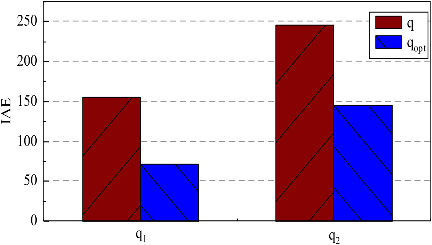
Integral absolute error.
As shown in Figure 14, the IAE of the manipulator q1 and q2 reduced by 54.2%, and 40.8% with clearance compensation optimization respectively compared to the joint clearance state, the results demonstrate the effectiveness of the proposed method in trajectory optimization for manipulator systems with actual joint clearance conditions.
Analysis and discussion
This study systematically examines the impact of joint clearance on the precision of end-effector trajectories in a two-degree-of-freedom robotic manipulator, using both numerical simulations and experimental validation. The experimental results quantitatively verify that the proposed generalized policy learning-based control framework with integrated clearance compensation: (1) effectively mitigates nonlinear clearance dynamics, (2) implements stable active compensation control, and (3) significantly reduces displacement errors induced by revolute joint clearance disturbances.
Comparative analysis of experimental and simulation results demonstrates that the adaptive clearance compensation control method effectively reduces motion trajectory errors induced by joint clearance in robotic arm articulation. Although both approaches validate the method's efficacy, certain discrepancies in control performance exist between simulation and experimental measurements, as summarized in Table 3. Comparative analysis of simulation and experimental results for the adaptive clearance compensation control method demonstrates consistent reduction in manipulator trajectory errors caused by hinge clearances, confirming the strategy's effectiveness. However, as quantified in Table 3, measurable discrepancies exist between simulated and experimental performance metrics.
Comparation of simulate and experiment results.
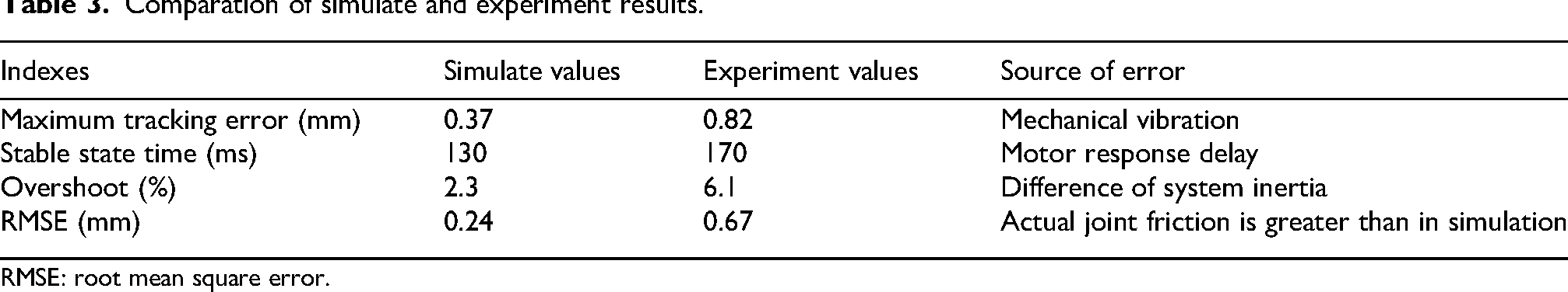
RMSE: root mean square error.
As shown in Table 3, after applying the ADP compensation control method, the end position of the manipulator in the clearance state exhibits a maximum tracking error of 0.37 mm in simulation and 0.82 mm in the experiment. The primary reasons for these errors are mechanical vibrations and stable state times of 130 and 170 ms, respectively, mainly due to motor response delays. The overshoot is 2.3% and 6.1%, and the corresponding overshoot distances are 0.61 and 1.83 mm, respectively. These discrepancies are mainly attributed to differences in system inertia, where the ideal values used in simulation do not account for the actual system's inertia. The root mean square error (RMSE) values are 0.24 and 0.67 mm, respectively. The increase in error is primarily due to the limitations of the actual encoder resolution, as well as the fact that the actual friction at the joints is greater than the simulated friction.
Both the experiment and simulation were conducted under the same articulation clearance and with identical size and weight parameters. After applying the ADP clearance compensation, the position error of the manipulator is <5%, and the velocity curves overlap by more than 95%. This fully verifies the effectiveness and robustness of the ADP clearance compensation method.
Conclusion
In this article, the impact of joint clearance on the end trajectory accuracy of a two-degree-of-freedom manipulator is investigated. A clearance compensation method leverages the augmentation and generalization system approach along with an ADP-based performance index function to simultaneously acquire feedforward and feedback control actions. An optimal controller is designed based on generalized policy learning for the manipulator's joint clearance compensation. An ADP-based finite-time online learning algorithm is developed, reducing the need for joint clearance system dynamics by directly updating the Bellman equations online without requiring complete system models. The simulation and experiment results demonstrate that the optimal controller effectively compensates for clearance dynamics, providing active compensation control. Unlike traditional algorithms, which rely on execution NNs, this method continuously updates adaptive evaluation and control actions simultaneously, without the need for iterative steps.
Future work will focus on enhancing the equivalent model of multi-degree-of-freedom manipulators with joint clearance to better address complex dynamic coupling in practical engineering applications. Particular emphasis will be placed on optimal tracking control under clearance-induced perturbations while accounting for hardware and environmental factors such as friction and thermal variations that may affect control performance.
Footnotes
Acknowledgements
The authors thank the editor and referees for the helpful comments and suggestions for improving the paper.
Funding
The authors disclosed receipt of the following financial support for the research, authorship, and/or publication of this article: This work was supported by the Natural Science Foundation of Shandong Province, National Natural Science Foundation of China (grant number ZR2024QE206, 52274132, 52474175, U23A20599).
Declaration of conflicting interests
The authors declared no potential conflicts of interest with respect to the research, authorship, and/or publication of this article.
Data availability
Data sharing not applicable to this article as no datasets were generated or analyzed during the current study.