
Abstract
Objective
Traditional computed tomography (CT)-guided tumor ablation procedures are often hampered by the need for repeated scans and significant radiation exposure, primarily due to challenges in manual needle insertion and the iterative realignment process. This research introduces an advanced intraoperative CT (iCT)-guided robotic system. The core aim is to enhance procedural accuracy and efficiency by implementing precise, real-time remote-center-of-motion (RCM) control for needle interventions.
Methods
This study develops an integrated iCT-guided robotic needle biopsy/ablation system. A key distinction from conventional iterative navigation systems is their capability for surgeons to dynamically adjust the intervention line in situ. Real-time visualization of relative positioning is achieved using 3D (three-dimensional) Slicer software. This is coupled with a novel and robust RCM control strategy, meticulously engineered based on screw axis theory and velocity twist, and further optimized with interpolation and feedforward control laws. This framework enables precise, surgeon-guided adjustments of the guiding catheter's posture throughout the procedure.
Results
The RCM control system effectively and reliably governed the motion of the robotic guidance arm. This ensured that the catheter tube consistently maintained its accurate orientation relative to the target even after multiple surgeon-adjusted posture modifications. Experimental validation demonstrated the system's high performance, achieving exceptionally low RCM errors as 2×10⁻⁴ m. Consequently, any deliberate pause during the robotic arm's movement could be utilized to define a precisely targeted and safe puncture path.
Conclusion and significance
Comprehensive numerical modeling and experimental evaluations using a TM5-700 robotic arm with phantoms have provided validation for the proposed screw axis-based RCM control concept. Integrating iCT guidance with this RCM system indicates increased precision, operational flexibility, and overall safety of robotic needle-based interventions. This work presents a noteworthy contribution with potential for clinical adoption in various minimally invasive procedures.
Keywords
Introduction
Image-guided percutaneous puncture biopsy/ablation is a treatment method in which an imaging method, such as ultrasound, computed tomography (CT), or magnetic resonance imaging (MRI), is used to aid the insertion of a thin ablation needle into deep-seated tumor lesions to extract a tissue sample or to apply energy to ablate the tumor tissue. Compared with the traditional surgical removal of tumors, percutaneous ablation surgery has the advantages of less bleeding, faster postoperative recovery, shorter surgery time, and the ability to preserve most organs; thus, the use of percutaneous ablation surgery is becoming popular in various procedures.1–4
In percutaneous ablation, the surgeon places a needle through the skin into the tumor. In contrast to minimally invasive surgery, percutaneous ablation does not involve the use of a camera for observation, and the surgeon often relies on a CT scan or an ultrasound for guidance. Ultrasound and MRI are less suitable for imaging lung tumors because of the shielding effect of lung gas, and only CT can provide clear images of these tumors. 4 In contrast to ultrasound, which has real-time imaging ability, traditional CT is time-consuming. Patient movement during CT may result in inaccurate tumor localization. Moreover, manual puncture may cause deviation from the planned needle path. Therefore, repeated scanning is required in CT, and the iterative process can take several hours.
To address the unmet needs encountered in the clinical CT and puncture biopsy/ablation settings above, robot-assisted methods can be used to reduce the uncertainty involved in the puncture process. Robot-assisted percutaneous ablation is a stable and accurate process, and commercial systems are available for this process. A robot is fixed to a scanning bed for the robot and patient to be scanned simultaneously. For instance, Siemens introduced a C-arm system based on cone-beam CT (CBCT) that enables the surgeon to plan the puncture path on an imaging interface. The advantage of these systems is that they have a fixed coordinate relationship with the scanning bed; however, their bulky setup makes it highly difficult to recalibrate the patient's position. Other similar products include Innomotion (developed by Innovedic), Micromate (developed by ISYS), and DEMCON.5–8
The above system has certain drawbacks. First, the equipment in the operating room might obstruct the robotic-arm's movement, and the puncture posture might need to be changed. Second, the patient's other organs might lie on the puncture path, thereby necessitating a change in the puncture path. Moreover, the surgeon may wish to adjust the puncture path during the operation after observing the relative position between the path and the tumor. Ideally, the catheter should always point toward the tumor. This represents another unmet need for percutaneous ablation operations for the medical staff.
To overcome the limitations commonly encountered in percutaneous ablation procedures—where clinicians often face challenges in accurately targeting lesions, as reported in various research studies and observed in commercial systems—the integration of remote-center-of-motion (RCM) control technology offers a promising solution. A comparative summary of the relevant CBCT technologies is presented in Table 1.9–13

2D: two-dimensional; 3D: three-dimensional; CBCT: cone-beam computed tomography; CT: computed tomography; RCM: remote-center-of-motion.
RCM control has emerged as a critical technology for addressing the above limitations in percutaneous ablation procedures. By enabling instruments to pivot around a fixed point—typically the incision site—RCM control effectively mitigates the issues of needle path deviation, improves targeting accuracy, and minimizes trauma while enhancing precision. This technology directly addresses the challenge of maintaining consistent catheter orientation toward the tumor throughout the procedure. As presented in Table 1, when integrated with robotic-CBCT, RCM control offers significant advantages, including robotic precision, improved control, and optimized target acquisition. For example, in both clinical applications and research, AcuBot—developed by Stoianovici et al. 14 —is a robotic arm equipped with an RCM mechanism that can be remotely controlled by a surgeon.
Research on constrained kinematic control in minimally invasive robotic surgery under RCM constraints 15 has significantly advanced the field of robot-assisted minimally invasive surgery. Although Table 1 highlights that robotic-arm CBCT systems already contribute to workflow optimization and reduced procedure time, the integration of RCM control further enhances these advantages by reducing procedural variability. Some studies on RCM control also incorporate gravity compensation and the development of specialized end-effector design. For example, investigations into partial gravity compensation of surgical robots 16 demonstrated that counteracting gravitational forces improves system performance by minimizing undesired forces at insertion points. Furthermore, research on innovative end-effectors for robotic needle insertion systems 17 illustrates how targeted mechanical design addresses the specific requirements of percutaneous interventions. These innovations also help mitigate the specialized training requirement—one of the key drawbacks associated with robotic-CBCT systems, as noted in Table 1.
The limiting distal motion center can be achieved primarily through two approaches: mechanism design (mechanism-based RCM control)18,19 or appropriate control laws (programable RCM control).20–22 The present study mainly focused on programable RCM control as it offers greater flexibility during surgical operation compared to mechanism-based approaches and does not require additional mechanism design and installation. This approach effectively addresses the “fixed installation space limitation” associated with fixed CBCT systems, as noted in Table 1, while still ensuring precise control.
Some studies have proposed a dual-quaternion-based velocity controller with trajectory interpolation capabilities to satisfy RCM constraints. 23 The Jacobian matrix of the RCM point is combined with the Jacobian matrix of the robotic arm's linear velocity to form an extended Jacobian matrix. 24 Based on the constrained Jacobian matrix, the lateral velocity at the RCM point can be set as zero. 25 Additionally, the velocity term of the directional error toward the RCM can be constrained using null-space control. 26 Motion constraints are achieved by solving a constrained quadratic programming optimization problem. 27
As evident from the comparative analysis presented in Table 1, our integration of RCM control with robotic CBCT is designed to synergize the benefits of various systems while addressing their limitations. Although this integration introduces challenges, such as system complexity and additional implementation costs, the potential advantages—combining robotic precision with enhanced control and optimizing target acquisition—represent significant advancements for percutaneous ablation procedures. The comparative evaluation of fixed CBCT, robotic-arm CBCT, mobile CBCT, and our RCM-controlled robotic CBCT approach offers a comprehensive framework for understanding the evolution of image-guided intervention technologies. However, to date, limited research has proposed a control law based on the screw axis theory and velocity twist for controlling the RCM and end-effector attitude. Addressing this gap remains a promising direction for future work in our study.
Our approach aims to integrate the benefits of multiple technologies while addressing their limitations. In this study, we aim to develop an intraoperative CT (iCT)-guided robotic needle biopsy system with RCM control to overcome the limitations of existing methods. The primary objectives of this research are as follows:
To investigate and implement an effective RCM control strategy for percutaneous procedures. To implement a novel screw axis and velocity twist approach for the RCM control. To establish a precise spatial relationship between the robot workspace and the CT image space. To ensure consistent and accurate needle targeting throughout the positioning process. To develop an intuitive user interface for real-time visualization and procedure planning.
The proposed system establishes a precise spatial relationship between the robot workspace and the CT image space, enabling surgeons to accurately determine the distance between the puncture line and the target lesion. The proposed system features two complementary operation modes: a manual dragging mode for initial positioning and a computer-controlled mode for precise alignment. Surgeons can easily guide the robotic arm near the desired puncture path through manual dragging and then switch to the computer-controlled mode to achieve precise positioning under the RCM constraint. This ensures that the annular guide consistently maintains its orientation toward the target lesion.
We implemented RCM control using a screw axis and velocity twist approach, enabling the surgeon to plan needle position and orientation through the imaging interface. The novelty of the proposed system is that the cannula maintains its orientation toward the lesion throughout the positioning process, providing enhanced operational flexibility while maintaining precise control. This ensures that even if the surgeon pauses the robotic arm during its movement, the annulus remains correctly aligned with the intended puncture path. By maintaining this consistent orientation, our approach effectively overcomes several limitations of existing percutaneous ablation systems, offering a more accurate and efficient solution for clinical applications.
Control methods and experiments
Screw axis theorem and motion control
The screw axis theorem of finite motion, also known as the Mozzi–Chasles theorem, states that the finite or instantaneous motion of a rigid body in space can be represented as a rotation about an axis and a translation along the rotation axis. As illustrated in Figure 1, a movement from coordinate system {A} to coordinate system {B} can be interpreted as a rotation by angle θ from {A} to {A^’} about the screw axis, followed by a translation d in the direction of the unit vector ω ^ to reach coordinate system {B}. 28

Screw axis with limited motion. 28
If a 6 × 1 vector X is used to represent the screw axis, equation (1) is valid. The 4 × 4 matrix representation of this vector is expressed in equation (2).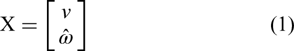


On the other hand, if the instantaneous rotational velocity 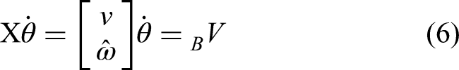
Figure 2 shows the conversion of velocity twist between different coordinate systems. The object velocity twist 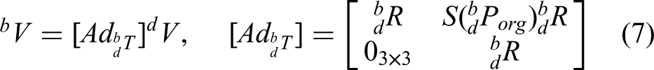

Speed screw conversion.
Equation (7) is the adjoint representation of the homogeneous transformation matrix
To implement a closed-loop control law
29
based on the screw axis theorem, let 

Derivation of RCM motion control
Based on equation (8), 


Starting and final coordinate systems.
Although the robotic arm can be moved from the initial coordinate system

Velocity relationship of the RCM in a continuous condition. RCM: remote-center-of-motion.
Based on Figure 4, with a simplification for the nonlinear system, the equation is as follows:
By differentiating the two sides of equation (12) with respect to time and then simplifying the resultant equation, we obtain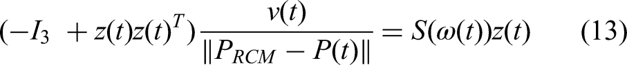
Equation (14) describes the relationship between the linear and angular velocities of the object velocity twist, which must satisfy the RCM limit in the continuous condition.
To ensure that the object velocity twist 
The relationship between velocity twist and RCM limit
In equation (12),
Based on Figure 5 and the previous research,
26
the differentiated term of the orientation error can be defined as follows:
Schematic representation of the orientation error.
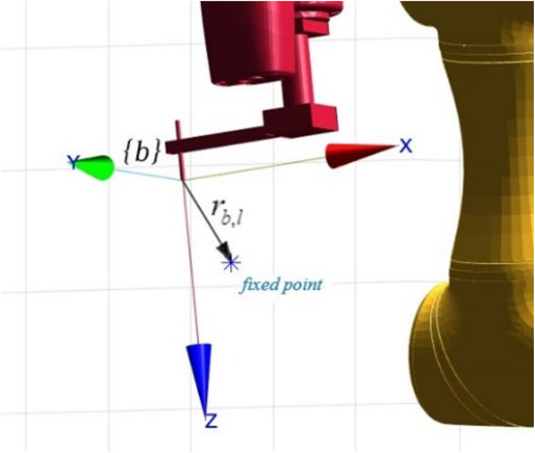
From Figure 6, the following differentiating expression with respect to time and rearranging the terms (with 

Schematic representation of the vector relationship in {b}.
Using equation (17), the relationship between 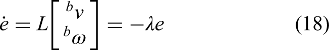

Equation (19) describes the object velocity spinor (in 
The term
Control algorithm of the robotic-arm system based on the RCM control
According to equation (20), the differences between the starting and final positions and postures affect the movement speed, making it difficult to determine the movement time and causing a high initial error in pointing toward the fixed point. In practice, excessive torque can be easily caused by the robotic-arm's joints.
To avoid the above situation, suppose that the interpolation in the “The relationship between velocity twist and RCM limit” section is performed between the initial coordinate system {i} and the final coordinate system {f}. In that case, the ideal coordinate system {d} in the control law is not only simply set as {f}, the interpolation coordinates at different times system, it is hoped that the casing coordinate system can start from {i} and follow the interpolation coordinate system to {f}. 23
As shown in Figure 7, postural change is initiated from the green coordinate system

Interpolation coordinate system.
Therefore, the interpolated coordinate system 
As mentioned above, the original control law in equation (20) can be expressed as follows, as the main control law based on the RCM control in this study:
The term

Block diagram of the system developed in this study.
Error characteristics used in RCM control practice
In this RCM control algorithm, two types of errors were examined through simulation and experimentation: (a) RCM errors and (b) position and attitude errors.
The RCM error is defined as the components

Assuming that the current coordinate system of the casing is 
The attitude error is expressed in the axial-angle corresponding to the rotation matrix, that is, the magnitude of the product of the unit vector W of the rotation axis and the rotation angle around this axis.
Constant maintenance of RCM points
In the control law, it is important to check whether the related limit point of the distal motion center remains constant in the real robot arm application. In Figure 9, 

Schematic representation of an endoscope's RCM. RCM: remote-center-of-motion.
Experimentally, to measure the control law performance, 
Experimental and simulation architecture
Figure 10 shows our experimental and verification architecture of the proposed system, which facilitates seamless data flow through control signals and feedback loops, enabling precise needle positioning under continuous CT guidance. The real-time CT-guided robotic needle system with RCM control has the following components, and the following provides a detailed explanation:
Image registration and path planning; Real-time visualization; Target identification. Executing the RCM control algorithms; Processing the trajectory data; Managing bidirectional communication between the imaging and robotic components. Receive control comments from the MATLAB system; Providing position feedback signals; Manipulating the needle assembly for precise insertion.

System architecture in this study.
TM5-700 robot and phantom
In this study, we used the TM5-700 six-axis collaborative robotic arm from Techman Robot (Figure 11(a)). This robotic arm features a maximum allowable load of 6 kg, a movement range of 700 mm, and a repeatability of ±0.05 mm. For safety purposes, the TM5-700 can immediately halt operations when it detects external forces or collisions exceeding a predetermined threshold. It also includes a key for releasing the motor brake, allowing manual guidance and movement of the robotic arm. Table 2 presents the basic specifications of the TM5-700 robot.

Experimental equipment: (a) TM5-700 six-axis collaborative robotic arm and (b) adopted phantom.
Specifications of the TM5-700 six-axis collaborative robotic arm.

For our experimental evaluations, we employed a phantom constructed from transparent silicone containing yellow silicone balls (Figure 11 (b)). Based on consultations with medical specialists, we designed the phantom with silicone components measuring 10, 15, and 20 mm to accurately reflect the lesion sizes typically found in human lung or liver pathologies. This carefully selected size range enables the effective assessment of the imaging system performance across clinically relevant scenarios.
Needle trajectory planning using the 3D Slicer software
In this study, we used the 3D Slicer software, an open-source platform developed by the Slicer Community, for medical imaging analysis. The extensible architecture of this software supports modular enhancement. The software enables CT visualization and three-dimensional (3D) reconstruction from two-dimensional (2D) slices. By leveraging its compatibility, we achieved comprehensive data and initial trajectory planning integration between the robotic system, RCM control comment using MATLAB, and the imaging interface, thereby enabling synchronized operational workflows across all components.
The captured CT images were imported into the 3D Slicer software, after which at least three noncollinear points were selected (Figure 12). As a result, the coordinates of these points in the robotic-arm and images spaces were obtained. Then, the Kabushi algorithm30,31 was used for the conversion between the image and robotic-arm spaces.

Reference points for the space transformation.
In the process of the 3D Slicer, the location of the lesion can be marked (Figure 13(a)) and the coordinates of the lesion in the image space are configured. The coordinate system of the casing before arrival was selected in the 3D Slicer according to the relevant requirements (Figure 13(b)). In addition to the conversion relationship between the two spaces obtained, it can also be used to obtain the angles of each joint of the robotic arm in real time using the Modbus TCP function in MATLAB software.

(a) Marked lesions and (b) needle position and posture.
Data transmission and RCM algorithm implementation using MATLAB tools
In this study, we used the MATLAB 2021b integrated development environment, developed by MathWorks Corporation, for data transmission and implementing the RCM core control algorithms. It was used to calculate the coordinates of the two ends of the casing in the robotic-arm space according to the forward kinematics.
The coordinates were calculated using MATLAB, and the transmitted data were then sent to the 3D Slicer through the communication network protocol for subsequent display. This data was then converted into a cannula object representing the casing body. The detailed transmission and display process is shown in Figure 14.

Detailed transmission and display process.
As shown in Figure 15, the upper right section of the matrix in the transmitted data computed from MATLAB is extracted and assigned to one of the markup point coordinates named “Points” through the communication network protocol, which represents the coordinates of one end point of the cannula in the image. In doing so, the data transmitted from MATLAB to the 3D Slicer can automatically update the coordinate values of the two end points. Therefore, when the robotic arm moved, the cannula was displayed on the interface of the 3D Slicer in real time.

Schematic representation of coordinate values updation with communication protocol.
The control law in this study was simulated using the RVC toolbox (a robot module library) and Simulink model with MATLAB 2021b. The system modeling diagram is shown in Figure 16. In this study, two types of errors were examined: (a) RCM errors and (b) position and attitude errors, through simulation and experimentation, respectively.

Diagram of the system modeling in the MATLAB simulation.
Results
Numerical simulation using the MATLAB software
The robotic arm used in the numerical simulation was the TM5-700 six-axis collaborative robotic arm. An extended sleeve processing part was added to the end of the arm. The axis defined by the tool coordinate system was the same as that of the sixth-axis coordinate system. The origin of the tool coordinate system was positioned relative to the sixth-axis coordinate system by translating −122.2 mm along the x-axis and 113.4 mm along the z-axis. The sampling time was set to 0.01 s, and the total simulation time was 20 s. The initial joint angles of the robotic arm, target joint angles, and tumor coordinates used during the simulation are, respectively, expressed as follows:


The movement time T was set to 15 s, and the errors of and in the control law equation (22) varied accordingly. Figure 17(a) shows the simulated RCM errors obtained under a fixed

RCM error simulation results (a) under a fixed
Figure 18 shows the simulated position and attitude errors. As shown in Figure 18(b), under the situation of a fixed

Position and attitude errors result: (a) under a fixed
Experimental verification
This section focuses on the experimental verification, and at least two repeated experiments were conducted and representative experimental results are shown. The initial position (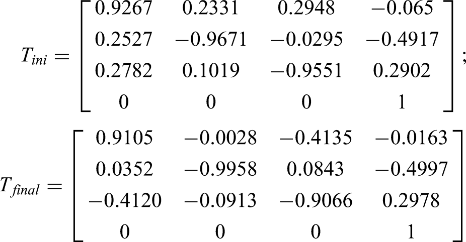
With real clinical need, the threshold of the RCM error was set to

Experimental (a) RCM error (orange:

Experimental (a) RCM error (orange:
Figure 21(a) to (d) sequentially illustrate that the cannula is pointed toward the RCM point during the movement of the robotic arm. The left side of Figure 21(a) to (d) shows the photo of the above scenario, and the right side displays the corresponding rendering in the 3D Slicer. The yellow lines point toward the lesion. Figure 21 shows that when the robotic arm was moving, it could be stopped at any location, and its needle could be lowered to poke the upper edge of a yellow ball used as a lesion (Figure 21(e)). This lesion was different from the previous setting on the upper edge of the ball, and the tip of the needle was stained with red ink for ease of visual identification.

(a)–(d) Cannula pointed toward the RCM point (left: actual image; right: 3D Slicer representation); (e) poking of a yellow ball with the needle of the robotic arm (the tip of the needle was stained using red ink). RCM: remote-center-of-motion.
Discussions
For applications, distal-center-of-motion restriction is implemented in minimally invasive endoscopic surgery. 32 Minimally invasive surgery involves opening several small holes in the patient's body and inserting the required medical equipment, such as endoscopes, into the patient's body through the opened holes. When an endoscope is used in a patient, its movement is limited to the center of motion of its distal end to avoid enlarging the small hole on the patient's body surface to causing wound expansion.
In this section, an analysis and discussion will be conducted comparing the two RCM control algorithms based on the work of reference 32 with the RCM control algorithm proposed in the present study. This comparative evaluation will also consider the behavior and impact of the γ parameter (introduced in the “Control algorithm of the robotic-arm system based on the RCM control” section) under these control strategies. Table 3 presents a comparative overview of these three control algorithms, which will be followed by a more detailed discussion.
Comparative performance of RCM control strategies.

RCM: remote-center-of-motion.
In Figure 22, 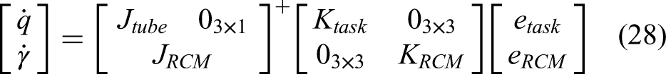

Schematic of a cannula's RCM. RCM: remote-center-of-motion.
Besides, if the control law is applied and added as the feedforward control term of the ideal trajectory, the following equation is obtained:

Figure 23(a) illustrates the control performance using the law defined in equation (28), showing the experimental error results with γ according to equation (27). The data revealed persistent oscillations in the RCM error even after the robotic arm stopped at the 15s mark. The position error also fluctuates beyond this time point.

Experimental error: (a) RCM error and position error results of updated according to Supplemental equation (S1) (
Figure 23(b) shows the enhanced control law expressed in equation (29), with γ updated according to equation (26). The incorporation of the feedforward control terms yielded the same changes in the RCM error above, confirming that the primary RCM mechanism effectively dominates and is maintained after the addition of the feedforward control terms. Notably, the position error magnitude decreased significantly due to the trajectory-tracking-specific feedforward addition. The system stability with feedforward control demonstrates robustness, as evidenced by the smooth RCM error convergence, despite the high-frequency position error oscillations before 15 s that interact with the continuous-time model assumptions. As described in the above and Supplemental material, when
Figures 24 and 25 show the errors obtained with the control law expressed in equation (29) under a fixed

(a) RCM error (orange:

(a) RCM error (orange:
A comparison of the position errors shown in Figure 24(b) and Supplemental Figure S3(b) shows that an excessively low
Figure 26 depicts the result of taking several Figures 19(b) and 20(b), and only displaying the position error. First, the control law used in this study was compared with the control laws expressed in equations (28) and (29) using the updated results obtained for

Position errors under (a) a fixed
Second, the control law used in this study was compared with those expressed in equations (28) and (29) using the updated
Figures 25(b) and 26(b) and Supplemental Figure S4(b) show that the position error obtained with the control law of this study was smaller than those obtained with the control laws expressed in equations (28) and (29). The addition of the feedforward control term reduced the jitter after 15 s. When the RCM error gain (
In addition to the analysis with the two specific control algorithms mentioned above, regarding the integration of RCM within existing CT-guided robotic devices, several analogous studies have focused on optimizing RCM manipulator control. For instance, one investigation
33
demonstrated a maximum end-effector tracking error of 5.1 × 10⁻³ m under optimal RCM configurations. Similarly, another study
34
reported positioning deviations of 1.78 × 10⁻³ m under RCM control, while additional research
35
indicated RCM point deviation errors not exceeding 2 × 10⁻³ m. In contrast to these findings from studies with comparable applications, the results presented in the “Experimental verification” section demonstrate that through strategic parameter configuration (
In this study, an initial phase of clinical operational validation was incorporated beyond the RCM control design, MATLAB numerical simulations, and real-time laboratory validation of the TM5-700 six-axis collaborative robotic arm employing the RCM control. This phase used an anthropomorphic model with the robotic arm directly in a clinical setting (Figure 27). It demonstrated the system's fundamental operational feasibility within a clinical context. Figure 27(a) illustrates the flexible deployment of the TM5-700 robotic arm in an operating room, independent of the fixed CBCT system. Figure 27(b) shows the system's use of a cannula for targeting lesions in the anthropomorphic model. Figure 27(c) shows the successful lesion localization and puncture, achieved using the 3D Slicer integrated with MATLAB to implement the RCM algorithm with feedforward control.

Initial clinical validation of the RCM control algorithm in this study with TM5-700 six-axis collaborative robotic arm. RCM: remote-center-of-motion.
In essence, control system inaccuracies—which significantly compromise precision—arise from the intricate interplay of algorithmic limitations and mechanical nonidealities (e.g. robotic arm compliance, joint friction, and actuator dead zones). While previous studies have explored RCM implementations to address these issues, our experimental approach combining RCM, interpolation techniques, and feedforward control has yielded superior results. Our research demonstrates that this comprehensive integration produces performance enhancements that surpass those achievable through either conventional RCM-only or RCM with feedforward control approaches. This improvement was achieved through careful calibration of parameters within the RCM constraint framework, such as
Conclusions
This study details the development and validation of an iCT-guided robotic needle biopsy system, distinguished by its real-time imaging capabilities and a novel RCM control. The system's core contribution is an RCM control method, founded on screw axis theory, that innovatively integrates interpolation and feedforward control. This integrated architecture demonstrably maintains continuous, precise RCM-constrained cannula trajectory toward targeted tumors during complex robotic-assisted interventions, while responsively adapting in real time to clinician-issued posture adjustments via the 3D Slicer imaging interface. This significantly enhances both RCM dynamic accuracy and operational flexibility. Consistently, simulation and experimental data confirm RCM error below
While demonstrating significant advances in precise RCM control and real-time image guidance, opportunities for future enhancement exist. The current system could be updated and benefit from artificial intelligence algorithms for intelligent target localization and adaptive path planning to further optimize robotic percutaneous intervention efficiency and accuracy. Moreover, while initial validation occurred in simulated environments, comprehensive case testing and statistical analysis across diverse conditions and subsequent clinical implementation with systematic data collection are crucial for thoroughly evaluating and refining the robustness and clinical efficacy of this integrated control framework within actual intraoperative CT settings.
In summary, this research offers a clinically promising solution for efficient and precise intraoperative CT-guided robotic interventions. Its unique RCM control methodology, synergized with real-time imaging integration, represents a notable contribution to the field of robotic-assisted interventional radiology.
Supplemental Material
sj-pdf-1-arx-10.1177_17298806251352059 - Supplemental material
Supplemental material, sj-pdf-1-arx-10.1177_17298806251352059
Footnotes
Acknowledgement
This research was supported in part by the Ministry of Education, Taiwan R.O.C. under the Higher Education Sprout Project and in part by the National Science and Technology Foundation under project no. NSTC 111-2811-E-011-014-MY3.
Funding
The authors received no financial support for the research, authorship, and/or publication of this article.
Declaration of conflicting interests
The authors declared no potential conflicts of interest with respect to the research, authorship, and/or publication of this article.
Data availability statement
Data sharing not applicable to this article as no datasets were generated or analyzed during the current study.
Supplemental material
Supplemental material for this article is available online.
References
Supplementary Material
Please find the following supplemental material available below.
For Open Access articles published under a Creative Commons License, all supplemental material carries the same license as the article it is associated with.
For non-Open Access articles published, all supplemental material carries a non-exclusive license, and permission requests for re-use of supplemental material or any part of supplemental material shall be sent directly to the copyright owner as specified in the copyright notice associated with the article.