
Abstract
This article presents the synthesis, parametric analysis with a semi-empirical model, and experimental validation of novel compliant remote center motion mechanisms with high cross-axis stiffnesses. The literature backs up ample use of rigid links in the synthesis of remote center motion mechanism in various applications. Compliant remote center motion mechanisms reported earlier are cable-driven mechanisms for endoscopy manipulation. On the contrary, in this article we propose spatial, compliant-link (leaf flexure link) remote center motion mechanisms (patent pending). Synthesis of the proposed compliant mechanism poses the main challenge of achieving precise remote center motion with prominent cross-axis stiffnesses. The proposed design is conceived using angularly assembled compliant links (with fixed–fixed boundary) which upon application of force undergo simultaneous twisting and bending resulting in the proposed remote center motion. Higher width as compared to the thickness along with angular arrangement gives the desired cross-axis stiffness. Extensive nonlinear finite element analysis establishes the accuracy of the remote center motion, high cross-axis stiffnesses, and the accuracy of the proposed semi-empirical model based on parametric analysis. Furthermore, the proposed mechanism is fabricated and preliminary experiments validate remote center motion in an example case.
Introduction
Movement over a circular arc having a fixed radius about an isocentric point is defined as remote center motion (RCM). RCM permits rotation around a distal fixed point without any physical revolute joint at that location. 1 Two commonly used approaches for achieving RCM are virtual RCM and real RCM. 2 A virtual RCM is achieved through computer control of robotic manipulator where RCM is generated virtually without having an actual physical constraint on the motion.3–5 Virtual RCM gives advantage of programmable location and radius of RCM within workspace constraints. However, it poses a disadvantage in terms of violation of dexterous workspace under noisy situation and close to singular points in workspace. Mechanism-based real RCM on the other hand is more robust under noisy environment and has simplified inverse kinematics. Several rigid link mechanisms for real RCM have been synthesized using circular linkages with bearings, circular motion guides, or parallelogram construction.6–14 Real RCM mechanisms are preferred over their virtual counterparts in high-reliability applications such as macro/micro-scale minimally invasive surgeries such as retinal surgery.4–14
Compliant mechanisms are known15–18 for their advantages such as higher accuracy, zero backlash, frictionless motion, and high precision in positioning. Compliant RCM mechanism, previously proposed in the literature, 19 is a cable-driven RCM mechanism reported for endoscopy manipulation. The mechanism displays limited accuracy in positioning. Several other types of compliant joints have also been proposed in the literature20,21 for compliant joint mechanisms. These joints do not impart RCM. One of the ways to build compliant RCM is to use compliant joint equivalent of rigid body RCM mechanisms. However, it yields mechanism with large errors at RCM point and the stiffness in parasitic motion direction cannot be independently controlled.
In this article, we synthesize (synthesis here refers to designing a combination of rigid and compliant links, their assembly, and relative positioning with respect to each other in three dimensions and designing the link dimensions), analyze, and experimentally validate a novel mechanism for achieving real RCM using compliant links in the mechanism (patent pending) yielding controlled compliance in the degree of motion (DoM) and independent high stiffness in the degrees of constraint (DoCs). The proposed mechanism is referred to in this article as compliant remote center motion mechanism (CRCMM). The proposed CRCMM is conceived using a peculiar angular arrangement of leaf flexure links. This arrangement leads to simultaneous twisting and bending of beams upon application of force causing the stage to have RCM. Nonlinear finite element analysis (FEA) of the proposed CRCMMs is carried out to demonstrate their performance in terms of achieving accurate RCM and high cross-axis stiffness. The proposed design is fabricated and assembled using recently published guidelines 22 and characterized for its performance.
This article is organized as follows: Section 2 presents the proposed mechanisms with one DOF motion. Particularly four mechanisms starting with a simple case are proposed. Section 3 then presents nonlinear FE analysis to demonstrate the RCM accuracy along with high cross-axis stiffness. To gain insights into physics of CRCMM and establish design process, thorough parametric analysis is carried out and results are presented in Section 3.2. A semi-empirical model for stiffness useful for design of such mechanisms is proposed based on the findings. Section 4 presents details of fabrication of the proposed CRCMM and results of experimental observations. Finally, Section 5 concludes the findings.
A novel compliant RCM mechanism
This section presents the development of the basic concept of the proposed compliant RCM mechanism in a step-by-step manner and the comparison of this mechanism with a double-parallelogram flexure mechanism as a special case. Consider a mechanism (CRCMM1) obtained by joining two disks (primary stage P1 and fixed disk) with several compliant links arranged in a circular fashion as shown in Figure 1(a). When a torque is applied on the primary stage P1, owing to peculiar geometric constraint, all links undergo simultaneous bending and torsion with both ends of each link having slope zero along the longitudinal direction. As it will be demonstrated later, this simultaneous twisting and bending of compliant links causes stage “P1” to move in a circular arc with center being the center of symmetry. Theoretical analysis of several plates or beams undergoing combined bending and torsion with large deformation, with three-dimensional (3D) boundary conditions and geometric constraints of problem under consideration, does not yield an analytical solution. Hence, we resort to numerical FEA to show in the next section that the rigid link P1 indeed moves along a circular arc and the center of this arc happens to be the center of the circular disk as could be understood intuitively.

(a) CRCMM1: compliant mechanism with links arranged on a full circle and (b) CRCMM2: 2-link compliant mechanism with RCM.
Several practical applications (e.g. minimally invasive surgery) may not have the possibility of having space all around the desired remote center of motion. In such cases, we propose a compliant mechanism (CRCMM2) which may be only a cut portion of CRCMM1. Such mechanism may have a minimum of two compliant links connected to sectors at either end as shown in Figure 1(b). When force is applied to the primary stage “P,” motion similar to that in the CRCMM1 causes the stage to rotate about an axis formed by intersection of planes of compliant links in undeformed position.
Parasitic rotation of the stage P1 in Figure 1(a) and the stage P in Figure 1(b) about an axis other than the longitudinal axis is prevented because of high flexural rigidity in the other directions owing to the much larger width of compliant links as compared to their thicknesses. In CRCMM2, however, because of loss of symmetry as compared to CRCMM1 the parasitic errors in rotation and translation are comparatively larger, which will be shown in the next section. We can see that in the proposed construction the stiffnesses in the parasitic direction are high and also there is better control to tune them by increasing the number of compliant links or geometry parameters while keeping the stiffness in the desired direction the same. For example, by increasing the width the rotary stiffness about the axes other than the desired motion can be increased keeping the stiffness in the degree of motion the same.
Although the mechanisms proposed in Figure 1(a) and (b) yield RCM about an axis, they are found to introduce parasitic motion in the axial direction, especially when the deformations are large. This parasitic motion is attributed to the fact that the beam length is constant (the stretching of the neutral axis of the beam is negligible). To compensate for this parasitic motion, an additional motion stage (secondary motion stage) is now introduced in each of the mechanisms CRCMM1 and CRCMM2 as shown in Figure 2(a) and (b). With equal force on both the primary and secondary stages, their motions would be identical when all four links are identical. However, parasitic motion of the primary stage would be compensated for by the parasitic motion of the secondary stage in the opposite direction. Hence, the primary stage would see no axial parasitic motion. A double-parallelogram mechanism used widely in the literature (see, for example, Awtar and Slocum 23 ) can be seen as a limiting case of the proposed mechanism when the angle between links of the mechanism approaches zero. For such mechanism, the remote center of motion would be at infinity. Surgical applications demanding incision point constraint (e.g. retinal surgery, laparoscopic surgery) can use the proposed CRCMMs for enhancing precision. Precision positioning system of hard disk drive arm can be another possible application of CRCMM4. CRCMM1 can be used in clutch coupling of automobiles for getting a smooth nonlinear noise-free operation or in a high-sensitivity torque sensor. The proposed mechanisms can also be used as mechanical amplification24,25 for rotary motion.

(a) CRCMM3: full circle compliant mechanism with RCM and (b) CRCMM4: 4-link compliant mechanism with RCM.
Analysis of the proposed mechanism
Analytical formulation of a link (considered as a beam) undergoing simultaneous bending and twisting with geometric boundary conditions was carried out. The problem was found to be coupled because, as the twisting occurs, the ability of the mechanism to bend in two perpendicular directions change and also it changes along the length of the beam. End boundary conditions induce unknown forces and moments on the beam and twist variation along the length of the beam is not linear. Considering these aspects, the analytical formulation did not yield a closed-form solution. Hence, we resort to a nonlinear FEA of the proposed mechanisms in this section.
The aim of the FEA is to assess the performance of the proposed mechanism in achieving accurate RCM and high stiffnesses in the parasitic direction and get further insights into the physics of mechanism by performing parametric analysis. Because of the large deformations involved (deformations are 50 times the thickness of compliant linkages), a nonlinear FEA 26 is carried out considering geometric nonlinearities.
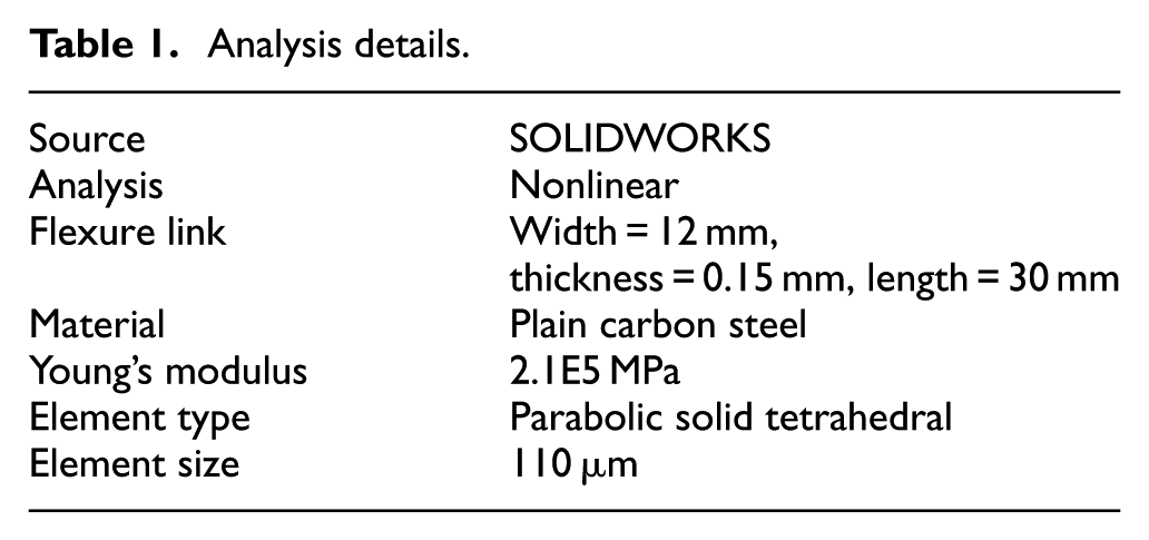
The key parameters for FEA are geometry, material type, element type, element size, and boundary conditions. The geometry of designs mainly contains the dimension of flexure links and their angular arrangement which decides the rotational stiffness of the proposed mechanisms. In order to understand the accuracy of RCM, the nominal dimensions of flexure link are taken as 30 mm length, 12 mm width, and 0.15 mm thickness. Furthermore, the parametric analysis with respect to changes in dimensions is presented in the next section. The selection of material is a key step in FEA. In practical use, flexure link needs to have high strength, good dimensional accuracy, and low internal stresses. Beryllium copper has an excellent yield strength-to-Young’s modulus ratio, but unsafe machining properties. Another popular choice is spring steel. Therefore, the material considered for flexure links is plain carbon steel with a Young’s modulus of 2.1E5 MPa. A parabolic solid tetrahedral element defined by four corner nodes, six mid-side nodes, and six edges is used to obtain a quality mesh. Furthermore, the smart element size of 110 µm has been used since the thickness of the flexure link is considered as 0.15 mm.
Details of the nominal geometry of the mechanism considered and FEA are presented in Table 1.
Analysis details.
The following cases are considered for FEA: Case 1: CRCMM1 (Figure 1(a)), Case 2: CRCMM2 (Figure 1(b)), Case 3: CRCMM3 (Figure 2(a)), and Case 4: CRCMM4 (Figure 2(b)). Boundary conditions imposed are as follows: Ends of all compliant links attached to the primary and secondary stages have shared nodes, while the remaining free ends of two compliant links are kept fixed. Load P is applied on the primary motion stage in the x-direction for all CRCMMs as shown in Figure 3(a)–(d). Convergence analysis was carried out by increasing the number of elements until the results of deformation did not show any appreciable change within 10–4 m. A needle is attached to the primary stage and the tip of the needle matches the proposed RCM in the undeformed position. As the force is applied to the mechanism, the displacement of the needle tip from the initial position would represent an error in achieving RCM. Deformation profiles presented in Figure 3(a)–(d) show the deformation patterns of the links undergoing simultaneous twisting and bending. The following subsections present the results of RCM accuracy and stiffnesses.

Finite element analysis of (a) CRCMM1, (b) CRCMM2, (c) CRCMM3, and (d) CRCMM4.
Parasitic errors and RCM accuracy
To assess the performance of the mechanisms in achieving RCM, several simulations were performed in Cases 1–4 mentioned earlier in order to obtain parasitic errors as a function of the increase in displacement measured in terms of the angular motion θ. Parasitic error is normalized with the deformation Rθ, where R is the radius of the RCM. Comparison of the longitudinal (z-direction) parasitic errors generated at the needle tip in Cases 1–4 is shown in Figure 4. The figure shows that the error increases with the applied force. Similarly, Figures 5 and 6 illustrate the parasitic error in the x- and y-directions at the RCM point, respectively. The normalized errors increase as a function of deflection θ because of the nonlinear stiffening behavior attributed to simultaneous twisting and bending. For the range of motion up to 12 degrees of the primary stage, the maximum normalized errors are 3.7 × 10⁻⁴ m and 0.7 × 10⁻⁴ m in the x- and y-directions for CRCMM4. For CRCMM3, the normalized errors are much lesser because of the symmetry. These nonlinear FEA results thus establish the accuracy of the RCM point.

Normalized longitudinal “z” parasitic error for all CRCMMs.

Parasitic error at RCM in the x-direction for all CRCMMs.

Parasitic error at RCM in the y-direction for all CRCMMs.
Next, simulations are carried out to investigate the stiffnesses in the parasitic direction caused by forces in the parasitic direction in the following two cases for CRCMM4 as a worst-case possibility:
Undeformed mechanism,
Deformed mechanism.
The most prominent forces are forces in ‘y’ (Fy) and ‘z’ (Fz) direction and moments about ‘x’ (Mx) and ‘y’ (My) direction applied on the primary motion stage. Although simulations are carried out to investigate stiffnesses in all the parasitic directions, the results of only the worst-case possibility are presented in Figure 7. It presents parasitic deformation in the z-direction as Fz is varied for (a) undeformed mechanism and (b) mechanism deformed under force Fy = 5 N. The results show that these parasitic errors are very small indicating that the cross-axis stiffness in the z-direction is indeed very high.

Normalized deflection in the z-direction at RCM for CRCMM4.
For such compliant mechanisms with large deformation, a complete definition of stiffness matrix is a topic of separate investigation in itself. This is because, for example, the presence of longitudinal force would change the stiffness in the x-direction and so on. Furthermore, the direction of longitudinal force either positive or negative would affect if buckling would happen or not. Hence, only indicative cases are considered above to demonstrate that the cross-axis stiffnesses are indeed an order of magnitude higher (or the deformations are an order of magnitude lesser).
Parametric analysis
Apart from cross-axis stiffnesses, rotational stiffness about the z-axis is the most important design specification for these mechanisms from any application perspective. The main parameters affecting the rotational stiffness are width, thickness, and length of compliant links. This subsection presents the parametric analysis of rotational stiffness with respect to these parameters to gain insights into the design aspects of these mechanisms. It is important to note here that the rotational stiffness changes with deformation because of the nonlinearities in the mechanism. Hence, the variation of stiffness with respect to the deformation angle of the motion stage is considered, in addition, in the parametric analysis.
To study the effect of variation in width, different widths from 9 to 14 mm are considered with fixed length and thickness. Variation is shown in Figure 8. Similarly, link thicknesses of 0.15–0.2 mm are considered to study the effect of thickness and lengths of 35–40 mm to study the effect of length on rotational stiffness. It can be observed from Figure 9 that rotational stiffness increases as the thickness increases as expected. In addition, as the angle of deformation “θ” increases, the stiffness shows an increasing trend. Figure 10 shows the decrease of rotational stiffness with the increase in length.

Rotational stiffness versus width.

Rotational stiffness versus thickness.

Rotational stiffness versus length.
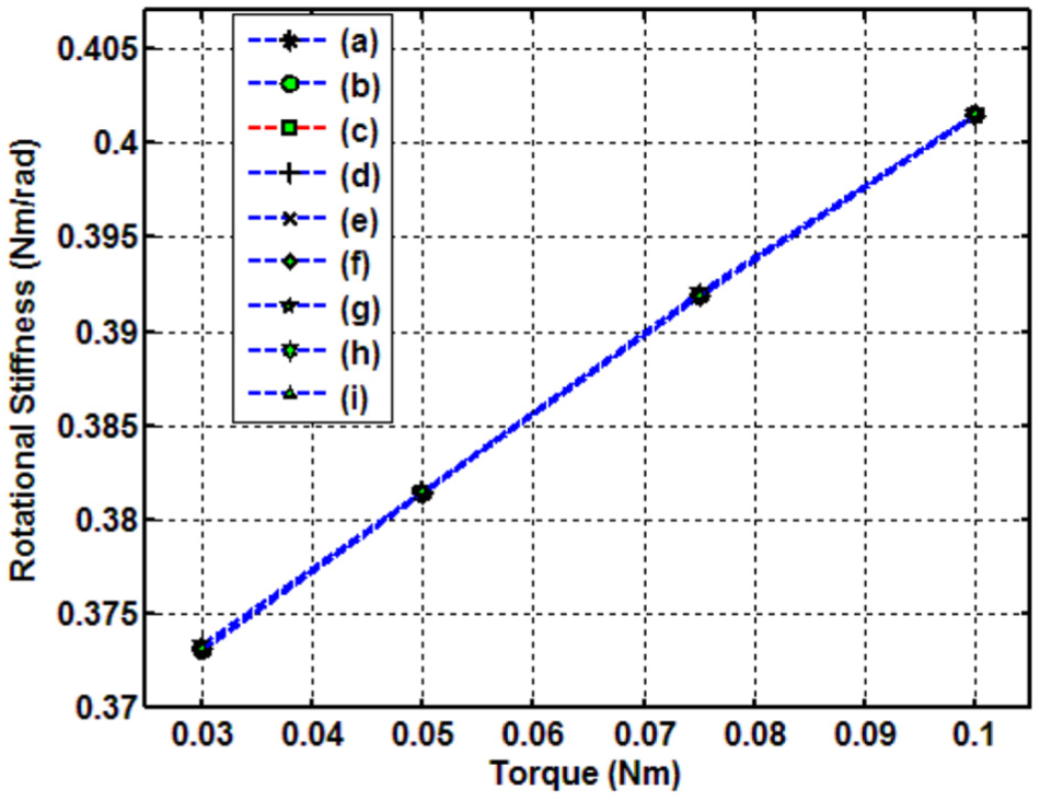
We observe that the stiffness varies nonlinearly with respect to width, thickness, and length as well as deformation angle. To capture this complex nonlinear behavior of stiffness in a simple intuitive manner, the following empirical relation is proposed
where “Kr” is the rotational stiffness in N m/rad, “W” is the width in meters, “T” is the thickness in meters, “L” is the length in meters, “E” is the modulus of elasticity in N/m2, and “θ” is the rotational angle of the primary stage in radians.
Physical insight into the proposed relation above is developed as follows: We used changing the powers with respect to θ to capture the simulated variation. Normally, the bending stiffness of a simple beam is proportional to
The curves generated using equation (1) are compared to the simulation curves in Figures 8–10. The comparison shows a close match between the results of empirical formula and simulations. We see that the empirical relation proposed above is dimensionally matching.
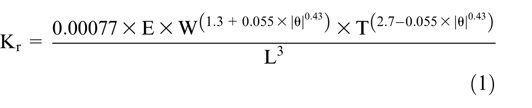
The angular arrangements of flexure links for the primary and secondary stages are important features of the proposed design. To understand their impact on rotational stiffness, different possible combinations have been considered as shown in Figure 12. We see that, for a specific set of width, thickness, and length values, all angular arrangements of flexure links demonstrate a similar variation in rotational stiffness of the mechanism as shown in Figure 11.
Rotational stiffness for different angular arrangements of flexure links.

(a) to (i) - Different angular arrangements of flexure links such as 18°, 25°, 30° for the primary stage and 55°, 60°, 65° for the secondary stage.
Fabrication and experimental characterization
This section presents first the fabrication details of the proposed CRCMM with 1 DOF and further presents the results of experimental characterization.
Fabrication of CRCMM
Compliant mechanism offers inherent advantages of being frictionless, highly repeatable, and having great design flexibility. These mechanisms can be developed in either monolithic or nonmonolithic way (meso-assembly technique). The monolithic design is fabricated using water jet machining, 27 wire electro-discharge machining (EDM), 28 or 3D printing. 29 In monolithic fabrication, the compliant mechanism is fabricated using a single material where nonflexible and flexible parts are manufactured using the same material. Such mechanism limits the use of multiple materials in the system and becomes expensive and at times infeasible, especially for 3D complex mechanisms. An alternative method of assembling various components of flexure mechanism is nonmonolithic technique. This method allows the use of different materials but poses problems in proper assembly. To overcome these problems, techniques presented in Gandhi et al. 22 are used. The proposed guidelines that are based on criterion similar to Grubler’s include a simple formulation to determine the number of pins to be used in assembly along with their locations. The fabricated model is shown in Figure 13. Furthermore, the accuracy of the mechanism is characterized in the next section using the required experimentations on the setup.

Fabricated mechanism.
Characterization of CRCMM
For accurate characterization of the RCM mechanism, the following procedure is used. A small needle with a tip radius of 30 µm is mounted on the primary stage as shown in Figure 14. The actuation is carried out manually by displacing the primary stage as shown in Figure 15. Several high-resolution images of the needle are taken using a Canon EOS 1000D and 2× magnifier at successive deformed positions of the mechanism. These images after some processing to enhance contrast are shown in Figure 16. In combination, these images demonstrate the movement of the needle tip on the circular arc as shown in Figure 17.

Experimental setup.
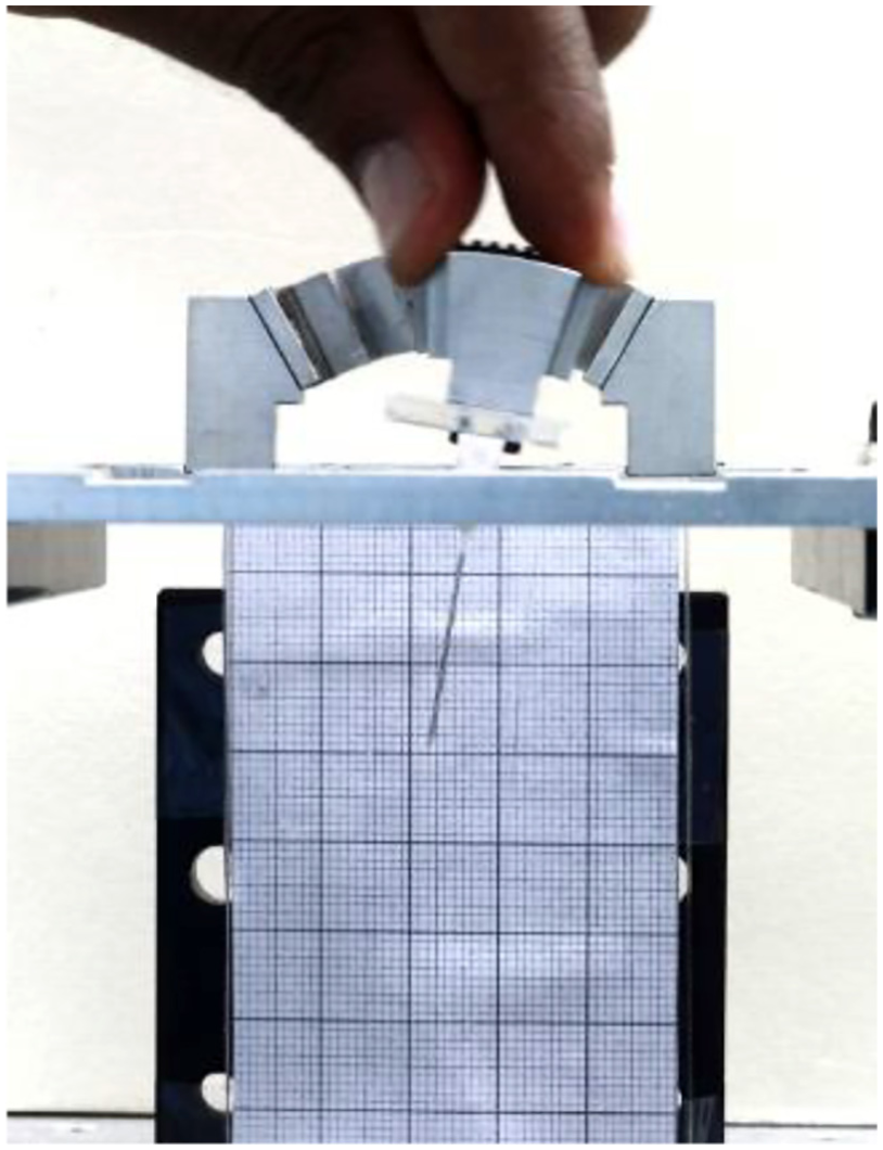
Manual actuation of primary stage.

(a) to (e) - Needle displacements under manual actuation of primary stage.

Movement of the needle tip on the circular arc.
Using “data cursor” tool from the figure toolbar in MATLAB, the positions of the needle tips are accurately determined and plotted in Figures 18 and 19 (with error bars). With angular movement of the primary stage, the needle tip also follows a circular arc having the center as RCM. Based on the measured positions, we used the three-point circle method to find the center coordinates.

Needle tips using MATLAB.

Needle tips using MATLAB (with error bars).
Using all possible combinations of the three points among the three sets as shown in Figure 20, the center (or RCM) has been calculated. Figure 21 demonstrates the needle tip curve and its respective calculated RCM points. A closer view of RCM points is presented in Figure 22 which shows the range of all calculated RCM points. The measured location of the center plotted (0 being the expected center based on construction of the mechanism) demonstrates the accuracy of the RCM with the proposed mechanism within ±10 µm in the x-direction and ±300 µm in the y-direction. The discrepancy can be attributed to measurement errors.

Sets for the three-point circle method.

Needle tips and the calculated RCM.
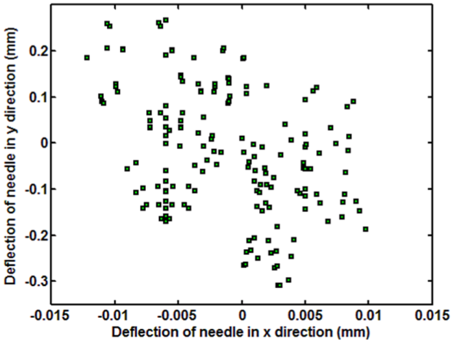
RCM points.
Conclusion and future work
A novel design of compliant mechanism for RCM is proposed in this article. The literature backs up ample use of rigid links and limited use of compliant links in the synthesis of RCM mechanism. In this article, step-by-step design and development are presented. The proposed CRCMM consists of the leaf flexure links arranged at an angle with respect to each other. Upon application of force, they undergo simultaneous bending and twisting to produce the desired RCM of the stage. Exhaustive nonlinear FEA using SOLID WORKS is carried out to demonstrate the accuracy of the proposed RCM considering errors in motion with respect to the fixed desired RCM. Furthermore, to gain insights into the physical and design aspects, the parametric analysis is carried out and an empirical model formulation is presented. This article further presents the fabrication of the proposed mechanism using the recently developed assembly techniques and preliminary characterization experiments support the proposed findings. It is envisaged that the mechanism would find applications in the area of minimally invasive surgery such as vitreoretinal and laparoscopy and in other areas including reliable motion of hard disk drive arm.
Footnotes
Acknowledgements
Handling Editor: Yong Chen
Declaration of conflicting interests
The author(s) declared no potential conflicts of interest with respect to the research, authorship, and/or publication of this article.
Funding
The author(s) disclosed receipt of the following financial support for the research, authorship, and/or publication of this article: Indian Council of Medical Research (ICMR).