
Abstract
This study aims to create a motion to manipulate paper without creating folds using high-speed vision, to replicate the human handling of flexible objects with a multi-fingered robot hand. By leveraging the physical properties of the paper, we propose a handling strategy that allows the paper to be tensioned in any direction. By elucidating the state transitions of the shape of the paper during dynamic manipulation, we achieved dynamic bending of the paper without creating creases. Two operation patterns were proposed: one using two hands to manipulate the paper from both sides and the other utilizing the inertia of rapidly swinging down the arm with one hand. Additionally, by clarifying the state transitions of the shape that appear during dynamic paper manipulation, we propose a method for bending paper dynamically without creating folds. This task was completed using image processing with high-speed vision to respond to paper deformation during the operation. The experimental results show that, by using high-speed visual feedback to monitor the shape of a paper, we can determine the appropriate timing for action switches, allowing the same operation to be executed on papers of different sizes.
Introduction
The handling of paper media is indispensable in daily life and is required in various scenarios. This operation is also known as paper handling. Although paper handling is straightforward when performed manually, it becomes challenging to model it when using machines such as printers or robots because of the varying properties, deformations, and changes in the humidity and temperature of different materials. 1 Consequently, specialized devices with unique shapes are required to ensure reliability. 2 However, these devices are not designed for other tasks, which results in low versatility. For instance, the roller-based paper-feeding mechanisms used in numerous office machines, such as printers and document scanners, enable fast paper feeding by turning pages one at a time using rotating tools 3 ; however, they struggle to flexibly adapt to various job processes. In contrast, the multi-fingered robot hand (MFRH) is designed to replicate the movements and skills of human hands, making it capable of performing not only paper handling but also a wide range of complex and diverse tasks, thus offering high versatility. By utilizing an MFRH, the efficiency and versatility of handling paper media can be significantly enhanced, enabling the execution and application of a variety of tasks.
Origami robots are a prominent example of paper handling using an MFRH. 4 Studies have been conducted on methods for handling paper that can be folded into complex shapes by leveraging algorithms that accurately predict paper deformation and utilize feedback from visual and haptic sensors. Research employing predefined motion primitives and adaptive feedback has effectively demonstrated precise origami folding, highlighting the potential for combining computational strategies with an MFRH to enhance paper-handling tasks. 5 Although the study of origami robots has achieved dexterous manipulation with an MFRH, it often includes hand mechanisms specifically designed for creasing, which may limit their versatility.
The integration of bio-inspired designs and movement mechanisms into the engineering of robotic hands is believed to facilitate the manipulation of flexible materials in innovative ways. For example, studies conducted by Nguyen et al. 6 have indicated that the incorporation of biological shapes and movements into robot design can facilitate the enhancement of their diverse manipulation capabilities. Such approaches provide a foundation for achieving more natural and efficient actions in complex operations involving tools or grasping flexible objects. Research on manipulating flexible materials by leveraging the versatility of a human-inspired MFRH includes studies on performing tasks using tools on paper. 7 New robot hands that can handle various tools such as scissors, pliers, and chopsticks have been developed. In the papercutting task using scissors, the experiments were conducted by suspending the target paper with adhesive tape. To manipulate objects as humans do while grasping a target, strategies are required to effectively constrain the position, posture, and shape of the paper through robot hand grasping.
Research on grasping paper with an MFRH includes studies in which a robot picks up and holds a flat, laid-down sheet of paper. 8 By utilizing marker-based visual information, a framework was developed that enabled real-time and robust tracking and modeling of the paper even under conditions of occlusion and significant deformation. 9 Research integrating visual and tactile feedback systems has demonstrated effective manipulation of deformable objects, emphasizing the importance of adaptive and precise control strategies for handling flexible materials. Understanding paper manipulation strategies and reproducing them with an MFRH is considered a crucial step toward synthesizing manual intelligence, which is observed when humans handle non-rigid objects. 10 Paper grasping was achieved by combining visually guided lifting and pinching techniques. However, they do not address the subsequent manipulation of the paper after lifting, nor do they discuss methods for effectively constraining the shape of the paper, which is necessary for tool-based operations.
Numerous studies on paper handling using an MFRH have focused on static and slow movements. During grasping, strategies have been employed to constrain deformation by directly grasping specific parts of the flexible material, significantly influencing task accuracy. This approach requires additional grasping points and repositioning movements as the operation becomes more complex. While there have been studies on the dynamic manipulation of flexible materials such as fabrics and strings,11,12 research on paper remains limited. In particular, no studies have addressed dynamic bending operations involving materials like paper that develop creases or undergo plastic deformation, highlighting the need for research on human-like high-speed paper handling.
Moreover, studies have shown that utilizing vision-based feedback enables accurate manipulation of flexible materials, which are typically challenging to predict during operation. This method demonstrated the capability to perform folding tasks across various types of fabric, proving its robustness to differences in material properties. 13 These results highlight the importance of feedback control in effectively handling flexible materials.
In this study, we address manipulation strategies that leverage the characteristics of paper to control its deformation and constrain its shape. We explored the grasping techniques used in human paper handling to effectively constrain the shape of the paper, and aimed to develop dynamic control movements using a high-speed MFRH and high-speed vision without creating creases. The handling of flexible materials is challenging because of their deformation during movement. Therefore, we propose an integrated system that combines high-speed vision and robot hands to provide millisecond-order feedback, enabling the successful execution of dynamic tasks, even when the object undergoes probabilistic deformation. Specifically, we focus on tasks involving the constraint of paper shapes using a MFRH and propose strategies to achieve this. Given that this study exhibits irregular changes in rigidity once creases are formed, our task emphasizes manipulation without creating creases. To realize this through two-handed and one-handed operations, we sought to replicate the human handling of flexible materials.
The remainder of this study is organized as follows. In the “Operating strategy” section, we examine human paper-grasping movements in detail to explore techniques for effectively constraining the shape of a paper. In the “Simulation method” section, we discuss a deformation model of the paper that utilizes its physical properties and describe the trajectories and strategies of the robot hand required to achieve this task. In the “Robot configuration and grasping strategies” section, we explain how two-handed and one-handed operations can be implemented using robot hands, proposing grasping techniques and configurations for hands to manipulate paper. The “High-speed visual feedback” section discusses high-speed visual feedback for extracting the appropriate operation timings for fast movements. Finally, the “Experiment” section presents the experimental results of the paper-bending and constraining operations using a MFRH.
Operating strategy
This article examines the execution of the action of “transforming a sheet of paper sagging under gravity into a taut shape” in two scenarios: using two hands and using one hand. Humans perform these actions to impart “tension” to thin, sheet-like objects, facilitating tasks such as passing, transporting, and inserting them. To extract elements that enable the manipulation of the shape of the paper without creasing, we present the results from capturing human gripping and constraining actions. Figure 1 illustrates the action performed with two hands, and Figure 2 shows the action executed with one hand. Common paper shapes that frequently appear when human paper manipulation is considered are depicted in Figure 3. In this action, the gripping position is at either the end or center of the paper, assuming that symmetric deformation occurs, thus simplifying the shape. Here, shape A represents the edge α of the paper, parallel to the x-axis, exhibiting a convex shape along the z-axis (with the central part raised and both ends lowered). Similarly, shape B denotes an edge α with a convex shape downward along the z-axis, shape D represents an edge β parallel to the y-axis, exhibiting a convex shape upward along the z-axis, and shape E denotes an edge β with a convex shape downward along the z-axis. Shape C represents a flat plane in which neither α nor β is curved. In terms of this shape, the task is to transform the shape from shape D to shape A, as depicted in the actions in Figures 1 and 2.
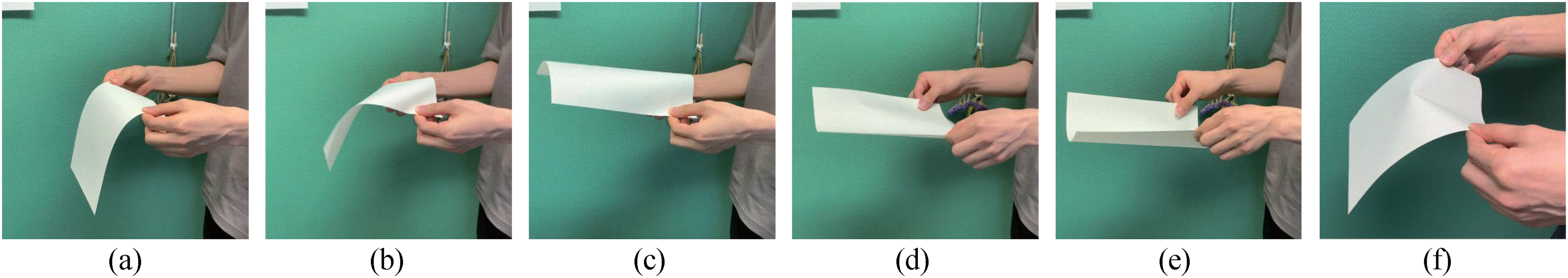
The dynamic bending operation of paper using two hands by a human. (a)–(e) Time-sequential series of manipulation processes captured in images. (f) Deformation of paper when attempting to move directly from (a) to (e), skipping (b)–(d), resulting in creases and failed operation.

(a)–(e) Dynamic paper bending maneuvers by humans using one hand were filmed and arranged in chronological order.

Common paper shapes observed during human manipulation. For shape C, which is a flat plane, we define the edge parallel to the x-axis as α and the edge parallel to the y-axis as β. In shape A, α is convex toward the positive z-axis, in shape B, α is convex toward the negative z-axis, in shape C, no edge is curved and it is a flat plane, in shape D, β is convex toward the positive z-axis, and in shape E, β is convex toward the negative z-axis.
Upon examining the action in Figure 1, the shape is altered by bringing the vertices on both sides of the paper closer to the center. Figure 1(a) shows the initial posture, and Figure 1(b) and (c) shows the process of changing the shape of the paper by applying force from both sides. Figure 1(c) and (e) shows the action of pushing from both sides; however, the resulting paper shapes differ. This is because the direction of bending (whether the edge α is convex upward or downward) is controlled by the angles of the wrists and fingers. If one skips the steps from Figure 1(b) to (d) and directly applies force to make edge α convex downward, an unwanted crease occurs, as shown in Figure 1(f), preventing further manipulation. Under gravitational conditions, it is impossible to directly change shape D to shape A without creating creases. Therefore, accurate and efficient manipulation of the paper without creases requires following the procedure shown in Figure 1, which involves transitioning through multiple shapes.
As shown in Figure 2, after performing an upward swing, a rapid downward movement is executed. Figure 2(a) shows the initial posture, and Figure 2(b) illustrates the transition to a new shape through an upward swing. In Figure 2(c), the abrupt halt of the arm's downward movement demonstrates how the free end of the paper, opposite to the gripping side, is bent because of inertia. Additionally, in Figure 2(b) and (d), when the shape becomes shape E, pressing with the fingers to achieve shape A maintains shape A with tension along the edge β.
From the above examination of human paper-bending operations, the following two elements can be identified as crucial for the successful completion of this task:
The sequence of shape transitions to achieve the desired shape. The appropriate timing for switching operations.
In more detail regarding (i), the sequence of shape transitions to achieve the desired shape: in the two-handed operation, the shape transitions must follow the order D→B→C→A. In the one-handed operation, the shape transitions must follow the order D→C→E→A. Therefore, it can be concluded that to change the location of the curved edge of the paper, passing through the plane of shape C is necessary.
Next, we consider (ii) the appropriate timing for switching operations. In both types of operations, the period during which planar shape C appears is brief because the transition is made from bending to constrained holding operations. If the constrained holding operation is not switched within this interval, creases form. To achieve appropriate timing for the switching operations, it is essential to accurately determine the moment when each edge of the paper is not bent and appears as a straight line.
Simulation method
In this section, we construct a simple simulation utilizing the physical properties of paper to verify the optimal grip positions and sequence of changes required to achieve the target shape. The objective of this verification is to extract the motions required to perform the paper bending operation with a robotic hand and utilize them to develop a motion strategy for the actual machine. For the three-dimensional (3D) simulation of the paper, this study adopted the position-based dynamics (PBD) method, which is a position-based approach. 14 PBD is highly efficient and enables stable simulations, making it widely used for the simulation of flexible objects. 15 In addition, because the positions of the manipulated points can be specified directly, it is easy to determine the overall shape when the trajectory of the gripped location is provided. Initially, the PBD updates the velocity of each vertex to predict the coordinates of the next frame. Subsequently, the solver directly manipulates the position of the object to iteratively adjust the predicted coordinates to satisfy the constraints. Finally, the pre- and post-adjustment positions were differentiated with respect to time to determine the velocity of the next frame. Below, we describe the additional constraints incorporated to simulate a paper using PBD to reproduce its physical properties.
Constraint condition
Paper exhibits a strong resistance to deformation under tension and is not prone to stretching. This characteristic arises from its structure, which is composed of plant fibers and binding materials, making the paper a developable surface. A developable surface has a zero Gaussian curvature that can be unfolded onto a plane. In other words, the internal distances remained constant and the surface area did not change, even when the surface was bent. Thus, we imposed the following two constraints to simulate paper:
Edge constraint. Bending constraint.
In this simulation, paper is modeled as a collection of particles arranged in a grid pattern, as depicted in Figure 4, with the constraints connecting them. In Figure 4, m and n represent the number of particles in the vertical and horizontal directions of the paper, respectively. xi,j ∈R3 represents the coordinates of the particle at elements (i,j), and de and db are the distances between the particles used in the constraints described below. In addition, gravity and air resistance were incorporated into the simulation to better replicate the movement of the paper in the real world. In this simulation, gravity acted as a constant downward force on the particles, while air resistance was modeled as a viscous damping force proportional to the particle's velocity. This approach effectively reduced the particle's velocity over time, reproducing the resistance experienced by the paper as it moves through the air.

The surface of paper modeled as a collection of mass points arranged in a grid pattern. Constraints are imposed on distances between mass points.
Edge constraint
An edge constraint was used to replicate the tension on the paper surface. Because paper is a developable surface, it can bend but not stretch. Therefore, the edge constraint maintains a constant distance between the particles on the surface of the paper, preventing tearing or stretching. The edge constraint Ce is expressed as follows:

Here,
Bending constraint
The bending constraint maintained a constant angle between the particles to simulate the bending rigidity of the paper. This was achieved by maintaining a constant distance between diagonally located particles, ensuring that the paper bended smoothly and preventing abrupt angle changes. The bending constraint Cb is expressed as follows:

Here,
Simulation results
In this simulation, the grid size was set to 13 × 13, and the distance between particles was set to 0.015 m. The simulation began with the paper surface in a flat state. Updates were made at regular time steps (dt), with a time step of 0.001 s. The mass of the paper is set to 0.005 kg, and dividing by the number of particles gives the mass of each particle as 0.00003 kg. The gravitational acceleration is set to 9.81 m/s2, and this value is applied uniformly to all particles. Air resistance is assumed to be proportional to the velocity vector, and the resistance force is calculated using a coefficient of 0.1 kg/m. The number of iterations for the constraint resolution was set to 100, and calculations were performed to ensure that the positions of the particles satisfied the constraint conditions.
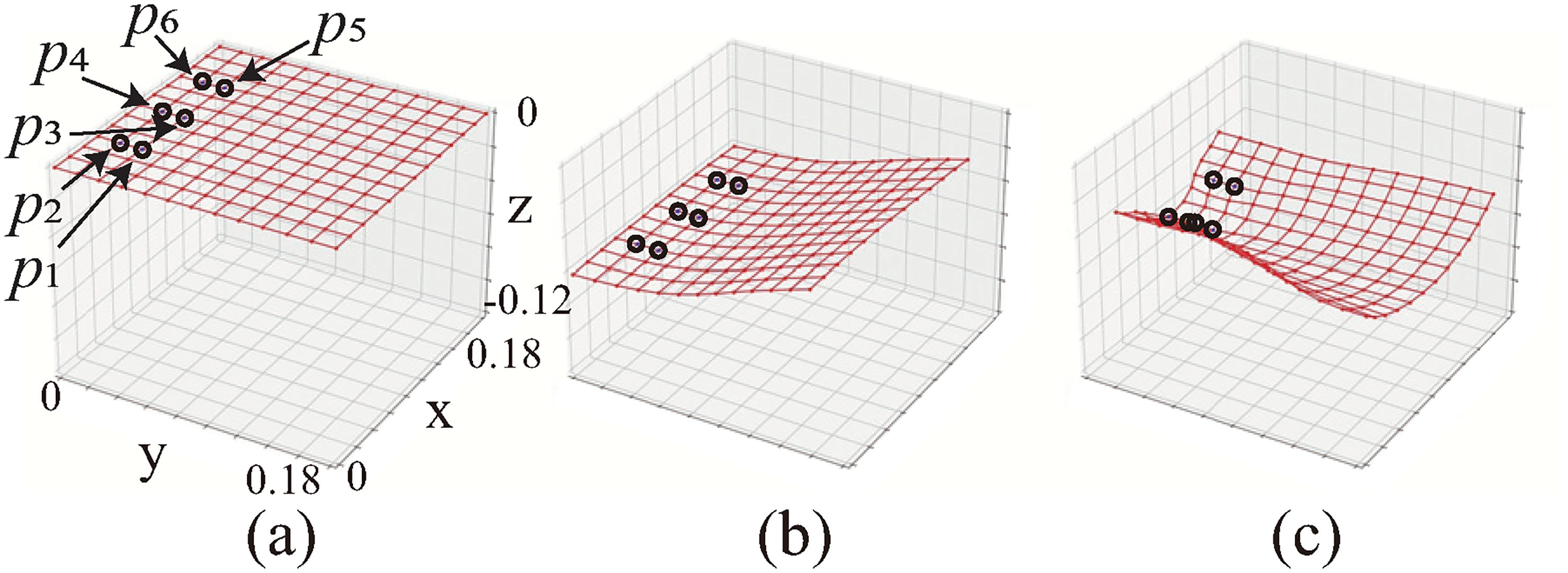
Figure 5 shows a simulation that reproduces the manipulation of paper using two hands, as shown in Figure 1. Using the black dots p1, p2, p3, and p4 shown in Figure 5 as control points, we provided trajectories that change linearly over time toward the target coordinates.

(a)–(c) Simulation of manipulation using two hands showing how the model deforms to satisfy two constraint conditions as control points (black dots) move along arbitrary trajectories. Transition from shape C to shape B can be observed.
Table 1 lists the target coordinates (x, z) [mm] for each control point at each time point.
Target positions of control points at each time in two-handed operation simulation.

When performing a bending operation in any direction, the movement that occurs before bringing the gripping positions closer is crucial. If the gripping positions are brought closer in a straight line, the paper becomes unstable, and the expected deformation cannot be achieved, as shown in Figure 6. Therefore, by moving the control points in the desired curvature direction before bringing the gripping positions closer together, a curved surface that is convex in any direction can be created. This corresponds to the manipulation by human hands, as shown in Figure 1, where the bending direction of the paper is controlled by the wrists and fingers. In two-handed operations, in which manipulations are applied from both sides, the bending direction can be controlled by providing at least two control points on one side.
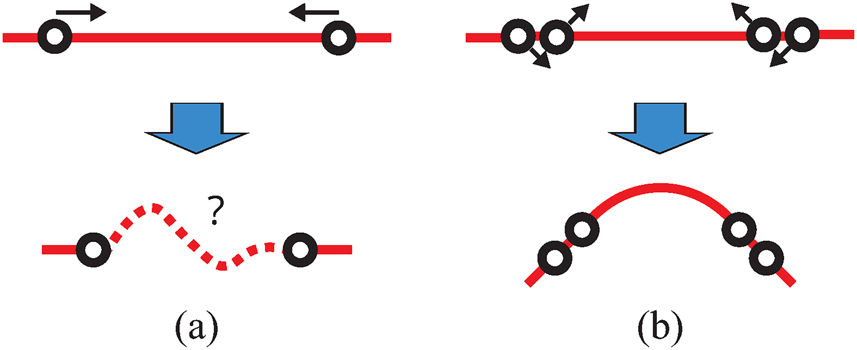
A number of control points are required to bend paper in any direction. (a) Two points are insufficient to fully control the curve. (b) By increasing the number of control points, the shape can be constrained and held.
Figure 7 shows a simulation of manipulation using inertia with one hand. In this operation, linear interpolation was used to provide trajectories that changed over time as the control points moved toward the target coordinates. In the simulation of one-handed manipulation, six control points are provided, as indicated by the black dots in Figure 7. As one-handed manipulation involves gripping from one edge, the method of constraining the shape from both sides, as shown in Figure 6, cannot be used. Therefore, the method was simulated assuming the use of three fingers. This method allows the direct specification of the coordinates of the vertices of the curve to constrain the shape.
(a)–(c) Simulation of one-handed downward motion.
Table 2 lists the target coordinates (x, z) [mm] for each control point at each time point.
Target positions of control points at each time in a one-handed operation simulation.

Figure 8 shows the comparison results when the downward speed is reduced. This attempt failed when the downward speed decreased, as shown in Figure 8. This is because, to utilize inertia, if the downward motion is below a certain speed, it is not achieved, and the state transition order shown in Figure 2 is not satisfied. If too much time passes, the paper will deform because of gravity. Therefore, in this action that uses inertia, a high speed is required for the downward motion to achieve shape D.

(a)–(c) Simulation of one-handed motion with reduced downward speed.
Robot configuration and grasping strategies
In this section, we demonstrate how to manipulate the shape of paper using an MFRH, as explained in the “Operating strategy” section. Based on the simulation results in the “Simulation method” section, we describe the configuration of the robot hand and specific strategies for manipulating shapes for both two-handed and one-handed operations. For the two-handed operation, we propose a method to determine the direction of curvature using the fingertips. In the one-handed operation, we explain the principle of manipulating paper using inertia from a rapid downward motion and a method for constraining the shape. The strategies and configurations explained in this section enable fast execution of the task of changing the shape of the paper using a low degree of freedom. Each finger of the robot hand used in this study is represented by a two-link model with two degrees of freedom.
Two-handed paper surface shape control operations
In the simulation shown in Figure 5, we demonstrate that by providing at least two control points on one side before the gripping positions are brought closer, the direction in which the curved surface of the paper bent can be determined. In manipulation with the MFRH, this operation utilizes the part corresponding to the fingertip, allowing gripping with a surface rather than a point. This creates a curved surface that bulges in any desired direction when the paper is pushed, thereby enabling shape constraints. A motion strategy image is shown in Figure 9. By conforming the paper to the part corresponding to the fingertip of one finger and pressing it with the another, the shape can be modified to bulge and constrain. The process of changing the paper surface from flat to convex is as follows:
Grip the paper with fingertips (initial posture). Shift the upper finger. With the upper finger shifted, push and move the gripping position of the paper from the fingertip to the fingertip. Constrain the paper in a convex state by pushing it toward the center.

(a)–(d) Strategy for reproducing two-handed manipulation using a robot hand.
One-handed paper surface shape control operations
Consider how to replicate the simulation shown in Figure 7 using an MFRH. The paper is grasped with three fingers of a high-speed MFRH and swung upward. Subsequently, by performing a rapid downward motion, an inertial force is generated against gravity to manipulate the shape of the paper. The motion strategy is shown in Figure 10.
Grip the paper with fingertips (initial posture). Perform a take-back motion to secure the swing-down range. Swing down quickly. When the paper surface is convex downward, push with the middle finger to constrain the shape.

(a)–(d) Strategy for reproducing one-handed manipulation using a robot hand.
High-speed visual feedback
Owing to the flexible nature of paper, modeling is challenging because of the variability in material properties, deformation, and changes in humidity and temperature, as well as the variety of paper sizes. For operations that switch from a downward motion to a restraining action, it is necessary to extract the appropriate timing based on the shape of the paper. However, the timing varied depending on the conditions. Therefore, we propose a method for determining operation timing and magnitude using high-speed vision. To identify the shape of the paper, we utilized the properties of perspective projection, which enlarges closer objects and reduces the size of distant objects. As shown in Figure 11, the edges of the paper captured by the camera were distorted in the direction of the curved surface. By analyzing the degree of bending of these edges, we determined the shape of the paper using image processing. We printed markers on the paper and considered the shape of the paper as viewed from high-speed vision. Below, we describe the specific processes involved in fast-tracking and shape identification.

Image processing method illustration. The shape of the paper is determined from the curvature of its edges by utilizing the properties of perspective projection.
Four black dots were printed at equal intervals as markers on the edges of the paper. For high-speed processing, the markers are limited to four points, which is the minimum number required to determine the cubic spline curve described later. The captured images were converted to grayscale, and threshold processing was applied to extract and calculate the centroid positions of the markers. We used the self-window method for marker tracking, which is effective for high-speed vision. 16 In high-speed vision, the time difference between frames is small, and the movement of markers during this interval is considered sufficiently small, making this method effective.
Next, we describe a method for obtaining the contour information of a paper using tracked marker coordinates. In this study, we employed cubic spline interpolation to obtain the trajectories of the curves in the contours of the paper. Using a parametric cubic spline interpolation, we calculated the trajectory on the u − v plane of the camera coordinates, as shown in Figure 11. The curve approximation of discrete points using cubic splines involves connecting four discrete points to a cubic spline curve for interpolation. The same parameter values for the cubic spline curve were applied to all curves passing through the four discrete points. Therefore, a smooth trajectory that passes through all marker coordinates obtained from the four tracks can be generated using a single cubic spline curve. Using the cubic spline curve derived from the marker coordinates, we calculated the curvature to determine the direction in which the paper was bent. The sign of the curvature indicates whether the curve bulges outward or inward, as observed by the camera. This method enabled the identification of a marked edge at a rate of 300 Hz. With this high-speed image processing, it is possible to accurately determine the shape even of paper moving rapidly owing to actions such as swinging down.
Next, we describe the method for obtaining the contour information of the paper using the tracked marker coordinates. In this article, we employ cubic spline interpolation to obtain the trajectory of the curves in the paper's contours. By using parametric cubic spline interpolation, we calculate the trajectory on the u−v plane of the camera coordinates, as shown in Figure 11. The curve approximation of discrete points using cubic splines involves connecting four discrete points with a cubic spline curve for interpolation. The same parameter values for the cubic spline curve are applied to all curves passing through the four discrete points. Therefore, a smooth trajectory that passes through all the marker coordinates obtained from four trackings can be generated with a single cubic spline curve. From the cubic spline curve derived from the marker coordinates, we calculate the curvature to determine the direction in which the paper is bending. The sign of the curvature indicates whether the curve, as seen from the camera, is bulging outward or inward. This method enables processing the identification of the marked edge at a rate of 300 Hz. With this high-speed image processing, it is possible to accurately determine the shape even for paper moving rapidly due to actions like swinging down.
Experiment
Figure 12 shows the configuration of the experimental system. To control a robot with high responsiveness to changes in a situation, a high sampling rate control is extremely effective. In this study, we utilized a dSPACE real-time controller to execute complex calculations such as sensor data processing, trajectory computation, and servo processing at high speed. The joint angles of the hand were controlled by PD control with a sampling time of 1 ms. The high-speed vision system used in the experiment was a Basler Ace acA800–510uc camera from Basler, which was operated at a resolution of 800 × 600 and a maximum frame rate of 511 fps. Imaging was conducted at ∼500 fps. First, the high-speed vision system captured the surface of the paper in real time. The images were acquired in real time using an image processing PC, which measured the shape of the paper. The measurement results are transmitted to a dSPACE real-time controller via UDP communication. The host PC sent a control program created in MATLAB to the dSPACE system to control the robot hand. The configuration of the MFRH is shown in Figure 13. The fingertips were made of a sponge material, allowing surface contact rather than point contact. The experiments were conducted using two fingers. Therefore, to simulate the manipulation of the paper with two hands, one side was fixed, as shown in Figure 14(a), to replicate grasping with two hands. This approach was necessary due to the limitations of our experimental environment. For one-handed operations, the movements of the joints of the first and third fingers were synchronized, allowing the recreation of the three fingers using a jig, as shown in Figure 13(b). The paper used in the experiment was of A4 size, measuring 297 × 210 mm.

System configuration for high-speed multi-fingered robot hand (MFRH) control using high-speed image processing.

Configuration of each finger and joint: (a) finger configuration for two-handed operation and (b) finger configuration for one-handed operation.
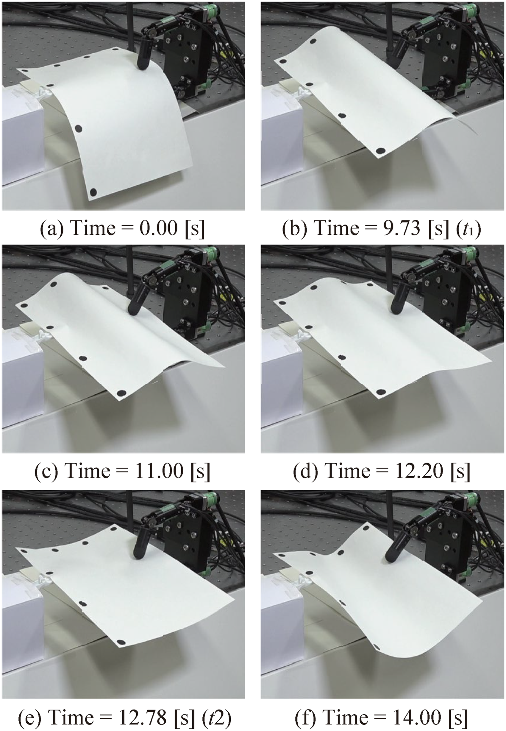
Due to experimental limitations, one side was fixed in place, and the operation was performed using two high-speed robotic fingers on the other side to simulate symmetric two-handed movements. (a) Time = 0.00 s, (b) Time = 9.73 s (t1), (c) Time = 11.00 s, (d) Time = 12.20 s (t), (e) Time = 12.78 s (t2), and (f) Time = 14.00 s.
Two-handed operations
Figure 14 shows a sequence of images obtained from the experimental results. In this experiment, the A4 paper was grasped by hand such that the short edge of the paper was parallel to the x-axis. The experiment began at the point where the paper was manually grasped. The figure shows the joint angle graph during the experiment, and another figure shows the curvature graph obtained through image processing. Paper surface manipulation using two hands followed the procedure outlined below. Here, t1 and t2 represent the timing of the changes in the shape of the paper obtained through image processing.
Initial posture: Manually grasp the paper. (0–8.0 s) Align the paper along the fingers to form a convex shape upwards. (8.0–9.0 s) Pushing. (9.0∼t1 [s]) Maintain posture. (t1∼10.0 [s]) Align the paper along the fingers to form a convex shape downwards. (10.0–12.0 s) Pulling. (12.0∼t2 [s]) Maintain posture. (t2∼13.0 [s]) Pushing. (13.0–14.0 s)
As shown in Figure 15 and 16, t1 is the moment when the curvature obtained from the long-edge contour of the paper becomes zero during pressing. Similarly, t2 is the moment when the curvature obtained from the short-edge contour of the paper becomes zero during pulling. When changing from shape B to shape A, it is necessary to go through a planar shape; hence, the paper is stretched until the short edge appears as a straight line from the camera's perspective. If the paper is overstretched, there is a risk that the fingers will slip on the paper surface, leading to a grasp failure. Therefore, appropriate timing was determined through image processing. In this experiment, switching timings t1 = 9.73 s and t2 = 12.78 s were obtained via image processing. Figure 16 suggests that this method successfully transforms paper from a drooping state due to gravity to a taut state, achieving the desired shape A. Using image processing information as a trigger to switch actions, the appropriate timing for manipulation was obtained. This resulted in achieving the goal of minimal movement and preventing positional shifts in the grasp due to slippage.
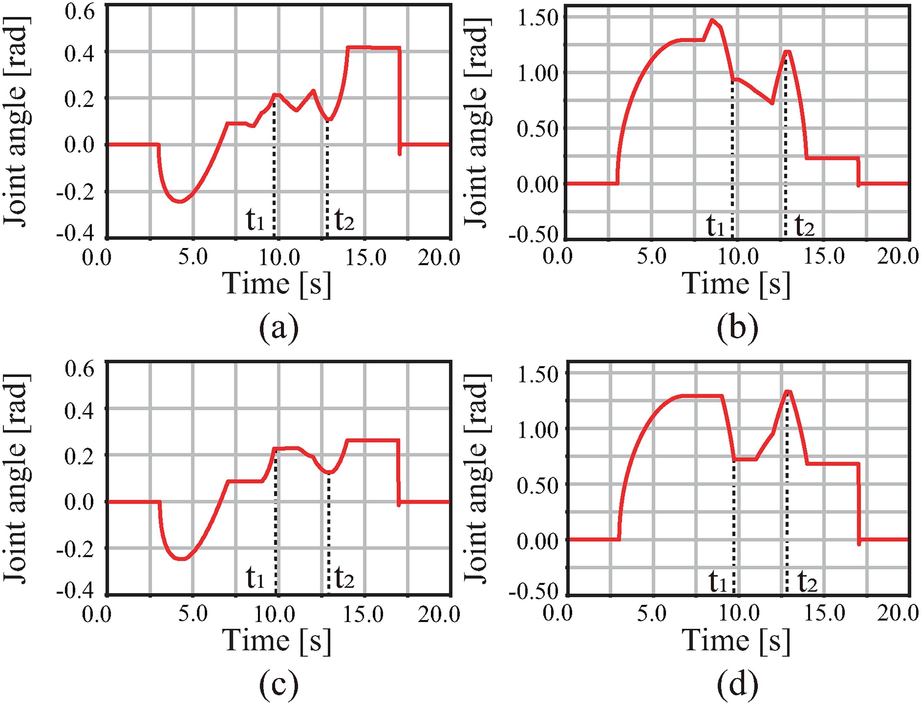
Data of joint angles of robot hand during two-handed operations: (a) Joint [0] in Figure 13(a), (b) Joint [1], (c) Joint [2], and (d) Joint [3].

The curvature of edges obtained through image processing during two-handed operations: (a) long edge of paper parallel to the y-axis, (b) short edge of paper parallel to the y-axis.
One-handed operations
Figure 17 shows images obtained from the experimental results. The images in Figure 17 were captured by using a high-speed video camera (800 fps) for debugging purposes. The procedure for manipulating the paper shape using one hand is as follows. Here, t denotes the timing of the changes in the shape of the paper obtained through image processing.
Initial posture: Manually grasp the paper. (0–16.0 s) Upward swing. (16.0–16.3 s) Stop at the peak of the upward swing. (16.3–16.4 s) Downward swing. (16.4∼t [s]) Middle finger pushing. (t∼t + 0.1 [s]) Return to initial posture. (t + 0.1∼t + 0.6 [s])
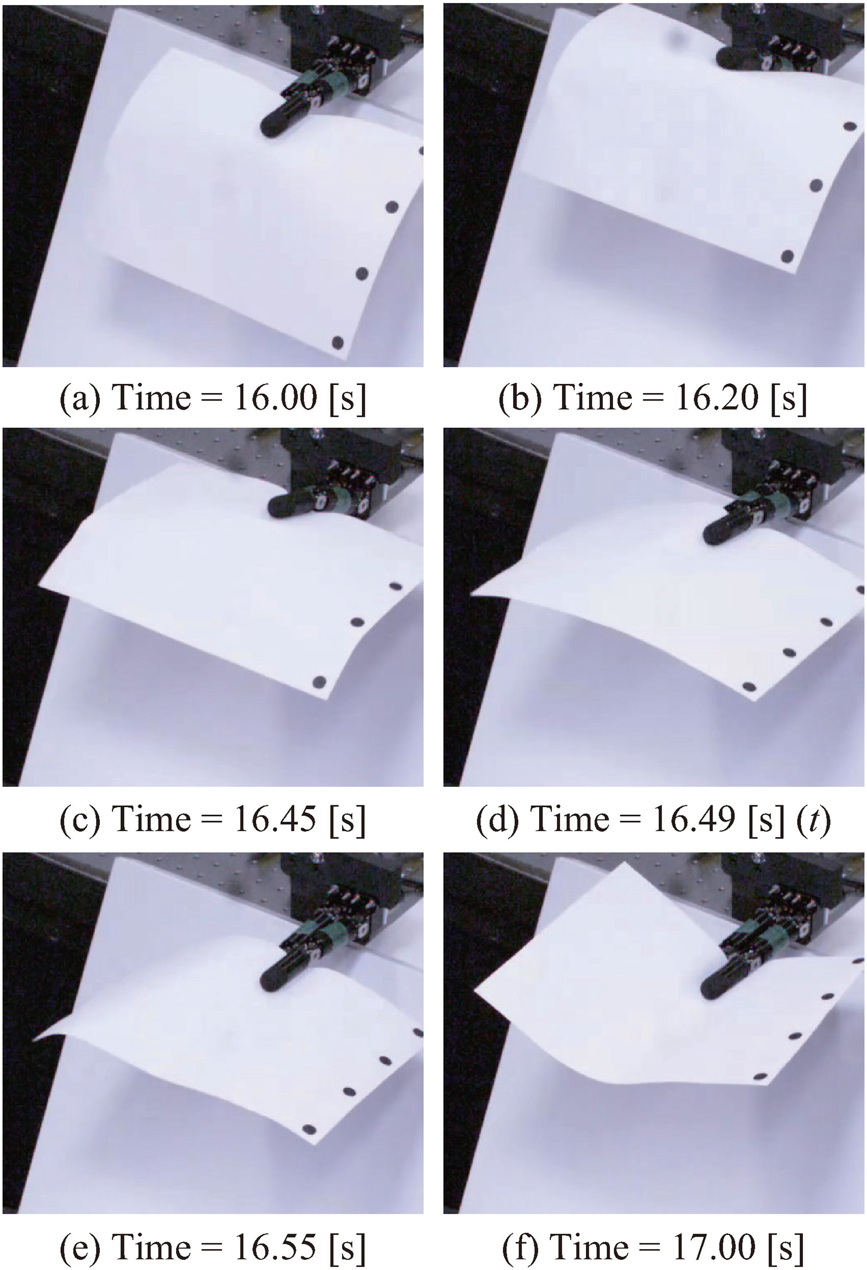
Experimental results of unimanual operations: (a) Joint [0] in Figure 13(b), (b) Joint [1], (c) Joint [2], and (d) Joint [3]. (a) Time = 16.00 s, (b) Time = 16.20 s, (c) Time = 16.45 s, (d) Time = 16.49 s (t), (e) Time = 16.55 s, and (f) Time = 17.00 s.
Timing t is defined as the moment when the paper reaches planar shape C while swinging down. This was identified when the contour of the short edge of the paper appeared as a straight line from the perspective of the camera. Thus, the instant at which the curvature of the cubic spline curve of the short edge becomes zero, as detected via image processing, triggers a switch to shape-constraining action. In this experiment, the transition time from the downward motion to the restraining operation was determined as t = 16.49 s through image processing, and the joints were actuated accordingly as shown in Figure 18.

Data of joint angles of robot hand during unimanual operations.
This one-handed method for manipulating paper utilizes the inertia from the downward swing to dynamically shape the paper. Figure 19 shows the curvature of the short edge of the paper measured in real-time during the fast swing-down action, which takes 0.1 s. Even during high-speed movements, the shape of the paper can be identified through image processing, allowing appropriate timing of the action switches. This enabled the quick manipulation and constraint of the paper shape with minimal movement.
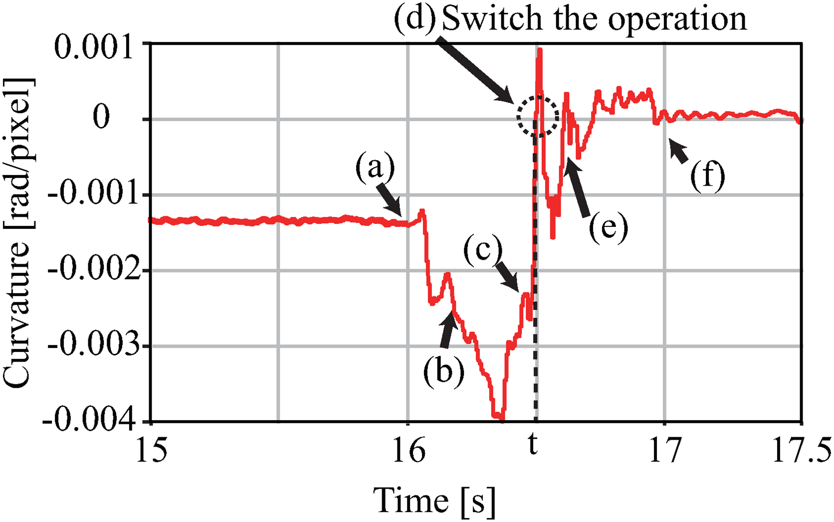
Curvature obtained from the short edge of paper parallel to the y-axis through image processing during unimanual operations.
In addition, as shown in Figure 20, the method was confirmed to be successful even when the orientation in which the paper was grasped changed. This method can handle various paper sizes robustly by adjusting the swing-down width through image processing. The effectiveness of the proposed method was evaluated by comparison with a method without image processing. After 30 trials of the swing-down action, the success rate was 63.3% without image processing, whereas the proposed method achieved a success rate of 90%. These failures were attributed to the inability to determine the appropriate timing for action switching owing to the loss of sight of the marker.

Situation when changing the orientation of the paper being gripped. The long edge of the paper is aligned parallel to the y-axis.
Discussion
Rather than attempting to track and control the complete 3D deformation of the paper surface, which typically requires complex shape reconstruction, our method focuses on detecting critical state transitions—specifically, the moments when the paper passes through a planar configuration. This simplified approach requires only four markers along the paper edges, rather than dense surface tracking. The paper's deformation between our defined canonical shapes follows predictable patterns due to its material properties, with the transition through the planar state (shape C) serving as a critical checkpoint for successful manipulation. The cubic spline interpolation between markers provides adequate shape information for timing control. This approach shares important theoretical connections with the concept of “knacks and focuses” proposed by Kuniyoshi et al. 17 in their analysis of whole-body dynamic actions. They identified sparsely localized convergence points in successful motion trajectories as invariant features crucial for both execution and recognition. Similarly, our shape C transition timing exhibits characteristics analogous to their foot-landing timing in the Roll-and-Rise motion—both represent critical points where trajectories converge and task success is determined. Our experimental results demonstrate that control freedom varies significantly before and after the shape C transition, aligning with their observation that trajectory distribution broadens between critical points to enable environmental adaptation. The binary nature of our key state detection (“curved” vs. “planar”) makes the system inherently robust to noise and measurement uncertainty. Unlike systems requiring precise shape estimation, our method only needs to reliably detect when paper edges appear as straight lines from the camera's perspective. This efficiency extends to hardware requirements, as the system achieves complex 3D paper manipulation using a hand with only two degrees of freedom per finger. Our approach leverages paper's physical properties rather than opposing them. The material's resistance to stretching helps maintain shape stability once configured, while gravitational effects are incorporated into the manipulation strategy, particularly in single-handed operation. The paper's natural tendency to form developable surfaces guides the transition between states. Future developments could proceed in two directions. First, applying Kuniyoshi et al.'s motion learning analysis methods to our system could enable more robust control laws through detailed analysis of successful versus failed trajectory distributions. Second, their psychological findings about human visual attention concentrating on critical points could inform human-interface applications. For instance, we could develop systems where operators only specify crucial transition timings while other control aspects remain autonomous. These extensions could contribute to building a general theory of invariant features in the dynamic manipulation of flexible objects. Additionally, further research could explore the relationship between the physical constraints of the task and the emergence of these critical points, potentially leading to more generalizable strategies for manipulating other types of flexible materials. Our approach demonstrates that effective manipulation of flexible objects does not necessarily require complete state observation and control, but rather can be achieved through strategic timing of key state transitions. This insight could inform the development of more efficient and practical robotic manipulation systems for a variety of flexible materials beyond paper.
Conclusion and future works
In this study, we aimed to perform tasks involving the manipulation and constraining of flexible materials, specifically paper, using a versatile MFRH without creating creases. By leveraging the physical properties of the paper, we propose a handling strategy that allows the paper to be tensioned in any direction. By elucidating the state transitions of the shape of the paper during dynamic manipulation, we achieved dynamic bending of the paper without creating creases. We demonstrated two methods: one using two hands to manipulate the paper from both sides and another using a one hand with a swing-up motion. Both methods successfully handled the paper deformation during the task. We propose methods for constraining the shape of paper using the fingertips of an MFRH and dynamic manipulation utilizing high-speed motion. The experimental results show that, by using high-speed visual feedback to monitor the shape of a paper, we can determine the appropriate timing for action switches, allowing the same operation to be executed on papers of different sizes. In the future, we plan to increase the degrees of freedom using robotic arms to achieve more complex movements. Additionally, by constructing a detailed deformation model, we aim to develop a system capable of conducting simulation-based experiments and compensating for the loss of visual information during operations. Furthermore, we plan to address other tasks, such as handling sheet-like flexible materials, including paper and film, and dynamic alignment.
Footnotes
Declaration of conflicting interests
The author(s) declared no potential conflicts of interest with respect to the research, authorship, and/or publication of this article.
Funding
The author(s) received no financial support for the research, authorship, and/or publication of this article.
Data availability statement
The data presented in this study are available upon request.