
Abstract
Quadrotors are small-sized, inexpensive aerial systems widely used for various indoor operations. Stable flight is a challenge for quadrotors due to low-cost sensors and indoor flight safety constraints add to their complexity. In this study, an Arduino based quadrotor is designed to test 2nd order Complementary filters for state estimation along with a controller with collision safety for indoor flight. Ultrasonic sensors are used for object detection during flight. Detailed hardware assembling along with the implementation of Complementary filter and PID controller is discussed. System tunning is done using the Heuristic method and system response is tested in real time. This study proves that by using the above techniques, a stable flight is achieved with collision safety using ultrasonic sensors.
Introduction
Since early 2000's up till now, Unmanned Aerial Vehicles (UAVs) have gained popularity in various applications ranging from surveillance, payload transfer, delivery, reconnaissance missions, firefighting, military, terrain mapping, smart city management and agriculture to education.1–7
Amongst these, small to medium sized quadrotors enjoy wide adoption. While these light weight and inexpensive quadrotors have made a lot of human tasks easier, their control and attitude estimation are a feat.8–10 Quadrotors are 2nd order, nonlinear and unstable systems. Low-cost Micro Electro Mechanical System (MEMS) sensors and onboard processors, with limited computational power, added to the complexity of real-time state estimation, system control and maneuverability.11,12 Over the years, different techniques have been designed to process and combine sensor data for state estimation and system control.13–15
Reliable control techniques gave rise to the use of quadrotors in indoor environments with obstacle detection and avoidance known as collision avoidance. Various active and passive sensors are used to achieve collision control, keeping in mind the weight and computational power constraints.
Existing studies have experimented with autopilots and quadrotor models to test attitude estimation and control with obstacle avoidance for indoor flight.16–18 Most of the studies19–23 have used a combination of complementary and Kalman filters for state estimation. While this combination is effective, it is difficult to implement and has high computational cost. For obstacle detection and collision avoidance, a variety of sensors are available but each suited to specific applications based on their cost, weight, power consumption and other limitations.24,25
With increasing complexity and cost of quadrotor design due to advanced sensors and techniques, their adoption for indoor flight is becoming difficult.8,26–30
This study focuses on the cost-effective design of a quadrotor with collision avoidance for indoor flight. It explores real time quadrotor state estimation and design of a controller, with collision avoidance, using low-cost sensors and control techniques for stable indoor flight. For this purpose, a quadrotor has been assembled using off the shelf carbon fiber frame, Brushless DC (BLDC) motors with Electronic Speed Controllers (ESCs), on board Microcontroller Unit (MCU) as flight controller, MEMS devices and ultrasonic sensors.
It explores the designing of an Arduino based flight controller for motor control, combining Inertial Measurement Units (IMU) and other peripheral sensors. For state estimation, Complementary filters are employed. Out of the available filters, Complementary filters show fine attitude estimation and reliability with far less complexity leading to wider adoption. This study has implemented 2nd order Complementary filter for stable indoor flight without any supplementary filters like Kalman.
After reliable state estimation, the task of quadrotor control and autonomous stability is achieved through widely used PID controller.31–33
For maneuverability and collision avoidance, a remote controller has been designed on a laptop which connects with the quadrotor through a Radio Frequency (RF) module. This controller is combined with distance data coming in from ultrasonic sensors for obstacle detection. These sensors are mounted on the quadrotor frame. Beyond a set range, if an object is detected, the quadrotor does not move in that direction even if the command from the remote controller is given. This digitally maintained safety radius protects the quadrotor from collision during indoor flight.
Overall, this study focuses on development of low cost quadrotor with 2nd order complementary filters as simple yet effective for real-time state estimation along with adaptive PID controller for indoor flight. The designed remote controller with collision avoidance, using low-cost ultrasonic sensors, is effective and reliable for indoor flight. The overall system utilizes low-cost sensors and has low computational cost. A graphical flowchart is shown in Figure 1. Which shows different section discussed in this study.

Graphical flowChat of the study.
System design
A fully functional quadrotor is designed for testing sensor data fusion and control mechanisms. The components used in the hardware development are listed in Table 1. System components, along with their details.
System components.

The quadrotor frame is assembled with motors installed, as shown in Figure 2. The ESCs connected to each motor are secured below the motor housing and the connection wires run through the hollow arms of the frame to the center for connection to the MCU.
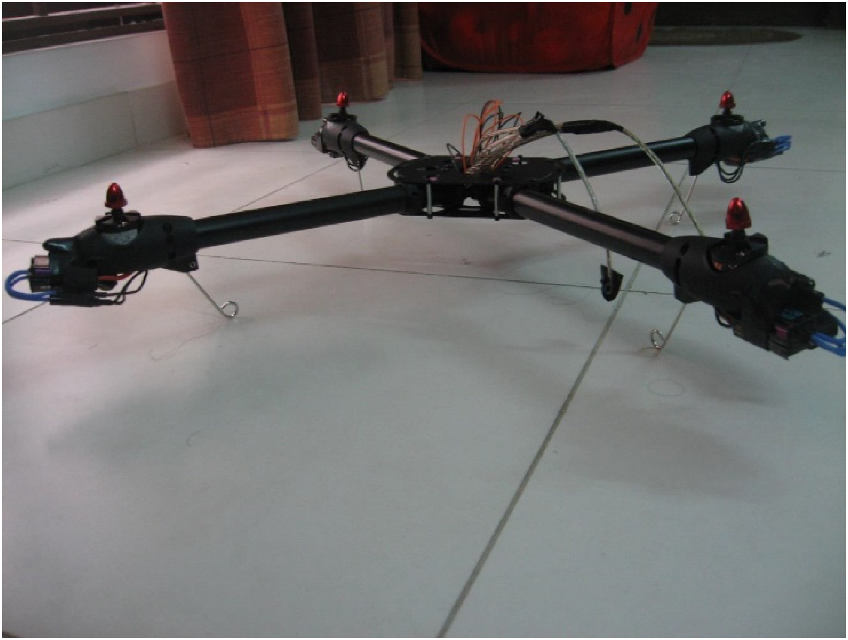
Quadrotor frame assembled and mounted with BLDC motors and ESCs.
The quadrotor is powered by an onboard 4000 mAh LiPo (Lithium Polymer) battery. A power supply circuitry is designed to operate high-powered motors and low-powered ICs from a single battery to manage the system's power requirements. The circuit schematic is shown in Figure 3. The use of a single battery with a power supply circuit is in consideration of the weight limitations of the system.

Power Supply Schematic.
This power supply board holds a toggle switch to turn the system on or off. It powers the motor through ESCs and regulator IC's power the Arduino board, IMU sensor, RF chip and ultrasonic sensors. An indicator LED shows the power is on. The board is fixed on to the central mounting area of the quadrotor frame while ultrasonic sensors are fixed on each side as shown in Figure 4(a).

Component Mounting on Quadrotor Frame. (a). Power Supply Board (b). LiPo Battery Mounting.
The LiPo battery is secured on the bottom of the central mounting area using elastic bands as shown in Figure 4(b). Special focus is given to placing all weight-adding components in the center of the frame for uniform weight distribution, facilitating a stable center of gravity for the Quadrotor.
On top of the power supply and sensor board, cardboard is placed as a dielectric to add a level for housing the Arduino mega 2560 board. The mega 2560 is powered through the barrel jack connector from the power board below. Arduino generates the PMW signal for motor control, takes IMU data through i2C bus, ultrasonic sensor data through digital pins and the RF module is connected with it through Tx/Rx pins. A fully assembled quadrotor is shown in Figure 5(a) and (b).

Assembled Quadrotor UAV. (a). Arduino Mounting (b). Full View Quadrotor.
Attitude estimation
Attitude estimation is the process of integrating multiple sensor data and knowledge about real-world objects into an accurate and useful digital representation through data fusion.
Data fusion processes are classified as low, intermediate or high depending on their processing stage. The resulting data or estimated state of the system is expected to be more informative and reliable than the raw data inputs. This study explores state estimation through an onboard IMU sensor, GY-80. It is a 10 DoF unit responsible for providing the orientation of the quadrotor during flight.
While GY-80 has moderate sampling rate of 100 Hz and is temperature sensitive, the study focuses on indoor flight where harsh weather conditions and complex flight trajectories are minimized. This makes the drift and sampling rate characteristics of GY80 manageable. While other advanced IMU sensors are available which are less sensitive to outdoor conditions and support complex flight trajectories with higher sampling rates, they come at higher price, power consumption and computational cost.24,25,34
Raw sensor data
GY-80 has a 3-axis, digital gyro which gives data in degrees per second (d/s) and requires no conversion code for the output. It has a built-in high pass filter to output data to reduce drift issues. Open-source code is used and modified to get the output data as shown in Figure 6(a). The x-axis shows the time in hours: minute: seconds (h: m: s) format and the y-axis shows the angle in degrees per second (d/s.)

(a). Rotational Angles from Gyroscope. (b). Rotational Angles from Accelerometer. (c). Yaw angle from Magnetometer.
The 3-axis digital accelerometer gives gravitational acceleration along each axis in meters per second square (m/
The 3-axis digital magnetometer gives data in degrees. The magnetometer needs to be calibrated according to the area. This is known as ‘magnetic declination’. The angle increases on a lift/tilt along the y-axis and decreases for opposite tilt. Open-source code is used for orientation according to the Earth's magnetic field. Raw data from the magnetometer is shown in Figure 6(c). The x-axis shows the time in h: m: s format and the y-axis show the angle in degrees.
According to the alignment of axes shown on the IMU chip, the roll is along y-axis and the pitch is along x-axis. When there is no rotation or acceleration along any axes, all outputs should be aligned to the reference zero of the graph. In case of any zero error, the offset values are removed by appropriate operation on the data i.e., addition or subtraction.
Each IC helps in calculating the four Euler/space angles. Once these angles are calculated, they are combined using filters for state estimation. In this study, data fusion is achieved through a 2nd order complimentary filter.
Complementary filter
Sensor fusion is the amalgamation of data from multiple sensors to get an output which is accurate, precise and reliable in all forms than the input data. For a sensor fusion process, input data does not need to originate from like sources. This study has utilized direct fusion using 2nd order Complementary filters, wherein data from accelerometer gyroscope and magnetometer is combined to give out an estimation of roll, pitch and yaw angles of the quadrotor in the real world.
The following formula is implemented for calculating the roll and pitch of the quadrotor

Raw data inputs for state estimation.

GP defines the level of trust in the Gyroscope and Accelerometer data in calculating the quadrotor orientation. It determines the weight given to each sensor's data.
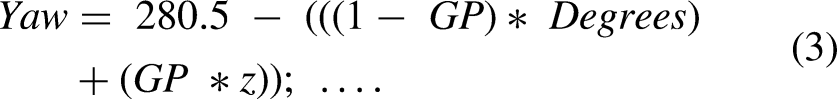
Fused data output is shown in Figure 7. Realtime implementation of the formulas is in Equations (1), (2), (3) and (4).


Complementary Filter Attitude Estimation.
As shown in Figure 7, the high yaw reading is due to the magnetometer offset stated in the datasheet ranging from −250 to +250. This offset is removed through a zero-error correction technique as shown in Equation (3).
Care is observed while implementing the Complementary filter because in most cases the stability issues are not due to lack of stabilizer controls but because of zero errors in the raw input data. If the attitude estimation is incorrect, quadrotor stabilization becomes next to impossible.
Control system with collision safety
A control system is designed to guide the quadrotor during flight. It is responsible for the movement and directionality of the UAV. The control system designed in this study consists of collision safety sensors, a remote controller and an onboard flight controller.
Collision safety sensors
Ultrasonic sensors, HC-SR04, ensure collision safety during the quadrotor flight. A total of five sensors are used; four on each side and one on top to limit the altitude for indoor flight.
The detection distance of the sensors is 2 cm to 500 cm with a high precision of approximately 0.3 cm. The relatively narrow sensing angle of 15 degrees ensures the sensors do not make a faulty detection of the frame's arms or the motor propellors as obstacles. The sensors are interfaced to give active distance detection to the Arduino Controller as shown in Figure 8. This distance reading is used as collision control input interfaced with the remote controller and IMU for stable indoor flight.

Collision safety distance input.
IMU sensors work well with a range of obstacle detection sensors like infrared, 35 LiDAR,36,37 Vision Based, 38 Time-of-Flight 39 sensors and radar. But as per the scope of this study, ultrasonic sensors are best suited for the application. 16
They have optimal range, low cost, low power consumption and are insensitive to lighting conditions. While ultrasonic sensors get effected by changes in air density in outdoor environments, the focus on indoor flight makes the range and accuracy of the sensors ideal within the scope of this study.40,41
Remote controller
In this study, a remote controller is implemented for steering the quadrotor in real time. Control Commands are generated through a laptop remotely connected to the quadrotor through an RF device as shown in Figure 9(a) and 9(b). It works as an Arduino serial interface. The device is used through serial monitor software “Docklight” for sending commands as Arduino's built-in serial monitor proves less powerful with this module.

RF Module Components. (a) Quadrotor RF chip (b) Laptop USB RF interface.
Within the onboard Arduino Controller, a simple switch case receives the remote controller commands and maps them to generate set points for the system.
Before checking the serial port for the control signal, the system takes the distance readings from ultrasonic sensors. If any obstacle comes within 50 cm of range on any side, further movement on that side is blocked even after input from the controller.
The Docklight based controller is shown in Figure 10 while Table 3 shows the remote controller commands and corresponding Set points generated by the Arduino controller for changing quadrotor states.
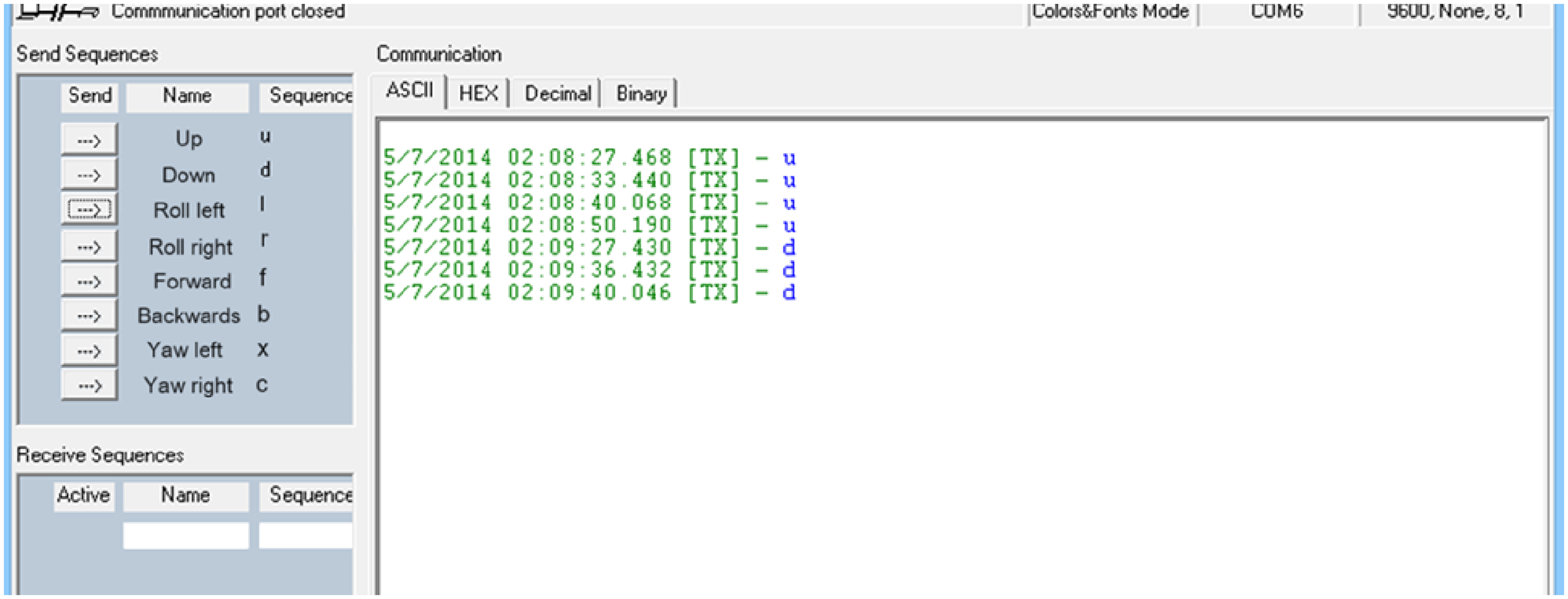
Control Inputs via Docklight.
Remote controller commands.

The controller signals with discrete values to change the roll, pitch, yaw and altitude of the quadrotor but these cannot be fed directly to the motors as inputs. These are only the set points for the system while control signals are generated from the microcontroller to achieve the desired points with stability. For this purpose, flight controllers are designed. Various controllers are implemented to stabilize the wobble due to environmental factors ensuring smooth flight of the quadrotor. This study has implemented PID controllers.
PID controller
PID is short for Proportional Integral Derivative Controller. It is a mechanism which is responsible for the stability of the quadrotor.
PIDs take an error value as input and generate an output to eliminate that error. The error value is the difference between the quadrotor state generated as output of the Complementary filter and set points generated by the remote controller interface. The generated error value is multiplied by individual proportional, integral and derivate gains. As a result, output signals for the motors are generated to attain and maintain the set points.
An adaptive PID controller is chosen because of its simplicity, robustness and low computational cost. Under the scope of this study, indoor flights are in relatively controlled environments where nonlinear drone dynamics are reduced thus a properly tuned adaptive PID is effective in maintaining stability and performing basic maneuvers. The adaptive PID controller caters for any uncertainties and disturbances even in indoor flight.42,43 Arduino's adaptive PID library allows the controller to be more aggressive or conservative based on the state of the system during flight.
Two types of gain parameters are set based on the system's offset from the Setpoints. If the quadrotor's current state and setpoints have a gap of more than 10 absolute points, aggressive gain parameters stabilize the system quickly. When the gap becomes less than 10 absolute points, conservative gain parameters are used to avoid overshoot. Gain parameter tunning is discussed in the next section.
Arduino adaptive PID library is used to implement the controller on each axis. It has been modified to give output within specific limits for the servo library. Table 3 shows the PID input error value, Attitude and Set points difference, and corresponding Outputs that are generated affecting respective quadrotor states.
These outputs are used in different combinations for driving motors. Simultaneous speed adjustment to each motor ensures stable flight and maneuverability. The output speed combination for each motor is shown in Table 4.
Remote controller commands.

Gain parameter tunning
Gain parameters are key components of the system which affect stability. Heuristic tunning is employed through a trial-and-error method for setting these values.
The trial-and-error method is selected due to its simplicity and low computational cost as compared to other tuning methods such as Ziegler-Nichols, Cohen-Coon or optimization-based methods.44–46 This method enables direct observation of the effect of individual gain parameters on the system's response, allowing for iterative adjustments that are particularly useful in systems with nonlinear or time-varying dynamics, such as the quadrotor in this study. Additionally, trial-and-error tuning eliminates the need for detailed system models and significant computational resources, making it a practical choice for resource-constrained environments.
While trial-and-error tuning can introduce costs when using extreme gain values, this was mitigated by starting with conservative initial estimates and making incremental adjustments while monitoring real-time system behavior. This approach ensured stability throughout the process and minimized the risk of introducing instability. Moreover, the hands-on nature of trial-and-error tuning provided valuable insights into the system's behavior, enhancing understanding of the interplay between gain parameters and system dynamics. For these reasons, the trial-and-error method was deemed the most suitable for the scope and constraints of this study.
To safely visualize the system response during the tunning process, the quadrotor has been fixed on a 4 Degrees of Freedom (DoF) tripod stand as shown in Figure 11. Since the battery is housed at the bottom of the central frame plate, it cannot be used to fix the quadrotor on the frame directly. To solve this, equal lengths of nonelastic plastic rope are used on each arm of the quadrotor frame to fix it on the tripod stand.

Quadrotor on 4DoF Tripod Stand.
The quadrotor displays roll, pitch and yaw while staying at one spot in 3D space. Altitude variations are observed by the rigid tripod extender rod which freely moves up or down along the vertical axis.
Complementary filter gain
The gain Parameter for Complementary Filter ranges between 0 and 1. GP for all equations of the Complementary filter is set to 0.027.
Values, both higher and lower than this were tested, and outputs were monitored on the plotter and in real time for adjustment.
The value for GP is selected such that the filtered output angles follow the response of angles calculated from the accelerometer tracking the slow-changing components of the orientation accurately given solely by the accelerometer.
PID controller gain
The PID gains have been tuned by the Guess and Check method. The process curve is observed on the plotter in real time and gains are adjusted in Arduino function to attain stability on all Euler axes.
The tuning method used in the study is classical which has its limitations as compared to adaptive tuning but based on the scope of this study and existing literature, classical tuning of PID works well for indoor environments with limited disturbances.42,47 It is also low in computational cost and power consumption. Since the PID controller itself is adaptive, it compensates, to a certain degree, for the classical tunning method in handling uncertainties and disturbances.
To start with the tuning process, I and D gains are set to 0 and only P is variated for reaching the set point swiftly. Once a suitable response rate and settling time are achieved, the I gain is increased to reduce the steady-state error. D gain is adjusted to minimize the overshoots introduced by Integral gain. While derivative gain reduces overshoot, a high value causes noise in the system so a balance between I and D is carefully set for overall system stability and response.
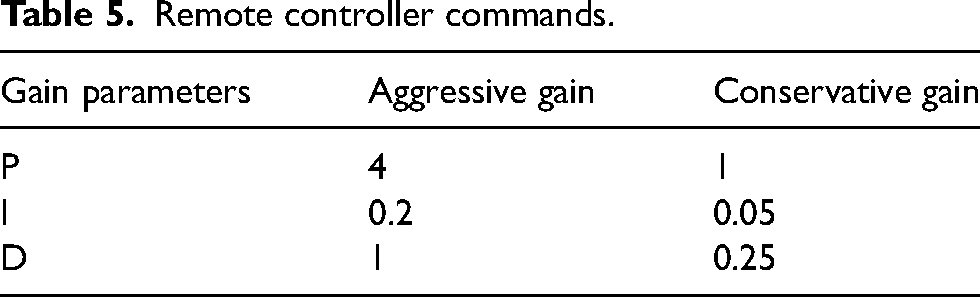
The final P, I and D gains for the quadrotor in this study are 4, 0.2 and 1 for aggressive tunning and 1, 0.05 and 0.25 for conservative tunning respectively. The gain values are shown in Table 5.
Remote controller commands.
Discussion
Based on the Gain Parameters the overall system response ensures a stable indoor flight. It can be seen in Figure 12. When the setpoint is changed to increase the altitude, the quadrotor's response curve quickly catches up, removing the difference while maintaining other quadrotor attitudes like roll, pitch and yaw for stable flight in the vertical direction only.

System response after tunning.
The quadrotor is tested for collision safety by bringing it close to a wall on its right. Ultrasonic sensors detect the object successfully and the quadrotor maintains stable flight on its spot even after a remote signal is given to it to roll on right.
Literature shows that GY-8048,49 and ultrasonic sensors41,50 have suitable performance for state estimation and obstacle avoidance during outdoor autonomous flight as well. They are often complemented with high level algorithms or other advanced sensors for improved performance and reliability. While the current system is designed for indoor flight, for outdoor flight, it can be updated with advanced IMU and obstacle avoidance sensors which will compensate for outdoor noise effectively.
Conclusion
This paper discusses the design and development of a cost-effective quadrotor with collision safety control. An Arduino mega board has been used as the central microcontroller with IMU for state estimation. The sensor data is combined using a 2nd Order Complementary filter for reliable state estimation.
A flight controller is designed on the Arduino board using PID controllers. Heuristic tuning process for the Gain parameters of the complementary filter and PID controller is employed. The process curve of the system after gain adjustment shows the successful and stable tuning of the system with a suitable response rate.
Through a remote controller on a laptop, steering signals are transmitted to the Quadrotor through an RF interface. Based on the remote signal, PID controllers generate motor outputs to attain the desired position while maintaining stability. The system also keeps checking for obstacles via the onboard ultrasonic sensors and if it is in proximity of any object below a certain threshold, the controller does not allow the quadrotor to move in that direction even if a steering signal is received.
This study validates the stable indoor flight of a cost-effective quadrotor using low-cost sensors. It displays that 2nd order complementary filters are simple, low on computational cost and reliable data fusion filters for quadrotor state estimation. The designed flight controller with collision safety allows stable and safe indoor operation of the quadrotor.
Footnotes
Declaration of conflicting interests
The author declared no potential conflicts of interest with respect to the research, authorship, and/or publication of this article.
Funding
The author received no financial support for the research, authorship, and/or publication of this article.