
Abstract
Tensegrity robots contain compression struts and tension tendons, allowing them to change their shape by controlling the lengths of members. Due to their excellent locomotion ability, they can play well when exploring complex environments. To protect the internal devices and meanwhile provide a base layer for thin film solar cells, membranes are proposed to cover the outer surface of the locomotive tensegrity in this study. A mathematical model for locomotive tensegrity with membranes is developed. A genetic algorithm incorporated with an incremental dynamic relaxation method is used to generate rolling gaits for the locomotive tensegrity with membranes. A classical strut-actuated 6-strut tensegrity system is taken as the basic model, and eight triangular membranes are covered on its outer surface to build a typical locomotive tensegrity with membranes. The influence of the membranes on the original rolling gaits generated by a numerical model of the 6-strut locomotive tensegrity without membranes is investigated. It is found that the effect of membranes becomes negligible when the relative stiffness between membranes and tendons is equal to or less than 1.2. When the effect of membranes is not negligible, the rolling gaits of the 6-strut locomotive tensegrity with membranes should be redesigned by using a numerical model taking the membranes into account. A physical prototype for the strut-actuated 6-strut locomotive tensegrity with membranes is fabricated, and tested to verify the feasibility of the redesigned rolling gaits.
Keywords
Introduction
The blend word tensegrity is used to describe a type of structure consisting of isolated compression units (struts) and continuous tension units (tendons). 1 The shape of the tensegrity is closely related to the prestress in the members. The unique properties of tensegrity structures are advantageous as the skeleton of some engineering platforms, such as smart structures,2,3 deployable structures,4,5 and robots.6,7
Recently, tensegrities have gained increasing traction in robotics due to their flexible and efficient nature. For example, Paul et al. 8 presented two tensegrity robots based on 3- and 4-strut tensegrity prisms and performed simulations and experiments. Friesen et al. 9 designed a duct climbing tensegrity robot with two linked tetrahedral frames and tested it numerically and experimentally. Chen et al. 10 developed a robotic fish whose main flexible structure was composed of rigid segments linked with tensegrity joints. Among different types of tensegrity robots, spherical tensegrity robots are most used to explore complex environments due to their excellent locomotion ability, such as extraterrestrial and disaster rescue scenarios. NASA11,12 built a simulation environment (the NTRT) and developed SUPERball robot based on the 6-strut tensegrity for planetary exploration applications. Khazanov et al. 13 manufactured a small 6-strut tensegrity robot that moved by using motors to vibrate it at specific frequencies for urban search-and-rescue. Chung et al. 14 used torsionally prestrained SMA (TPSMA) springs as actuators for tensegrity robots capable of fast rolling motions and jumping for multiple environments. Barkan et al. 15 designed a force-sensing 6-strut spherical tensegrity to help an operator assess a disaster site safely and remotely.
For the aforementioned application scenarios, energy self-sufficiency of the tensegrity robots is very important for sustainable use. One of the most effective methods is installing an integrated solar charging system,16,17 and it requires enough flat surface to install solar cells. Meanwhile, the previous tensegrity robot's open space design makes it susceptible to be interfered by the outside environment and thus decreases the robustness of locomotion gaits. 18 Covering the surface of tensegrity robots with membranes can provide room for the solar cells and shield the internal space from the outer environment. In space structure, membranes have been widely used as cover for tensegrity-based roof structures.19–22 In the space field, Sunny et al. 23 demonstrated that tensegrity systems with membranes may be treated as passive energy harvesting systems. Yang and Sultan24–26 presented a series of studies on the statics and dynamics of tensegrity-membrane systems based on a nonlinear finite unit model. Kurka et al. 27 investigated the mechanical behaviors of a tensegrity with six bars attached to a membrane which is proposed to substitute a satellite reflector antenna. In robotic field, Booth's team28,29 used membranes as carriers for sensors and actuators to build locomotive tensegrity-membrane systems.
To date, many methods have been proposed for dynamic analysis of tensegrity robots without membranes, such as the Runge–Kutta method, 30 multi-body kinematic and dynamic simulation, 31 and commercial physical engine. 32 And for gait generation of tensegrity robots, there are many methods as well, such as a genetic algorithm (GA),8,33–35 a greedy search algorithm, 36 and a physically embodied evolutionary algorithm. 37 In addition, for complex robotic systems, advanced machine learning algorithms combined with gait generators can provide advanced gaits. For example, Tutsoy38,39 used reinforcement learning (RL) algorithms to learn optimal control actions and proposed a central pattern generator (CPG) based reinforcement learning (RL) algorithm to balance a robot leg with 3-links. However, to authors’ knowledge, no study on the mathematical model and the method for generating rolling gaits of a tensegrity robot with membranes has been reported. In this paper, a 6-strut locomotive tensegrity robot with membranes is proposed and the influence of the membranes on the rolling gaits of the system is investigated.
The paper is organized as follows. A mathematical model of the tensegrity with membranes and a method combining a GA with an incremental dynamic relaxation method to generate rolling gaits are introduced in Model and method section. The configuration of the numerical model of a 6-strut tensegrity robot with membranes is given in “A 6-strut tensegrity robot with membranes” section. Rolling gaits section investigates the effects of the membrane on the rolling gaits of the tensegrity robot with membranes. Experiments section introduces a hardware tensegrity robot with membranes and performs locomotion experiments. Finally, Conclusion section concludes the work.
Model and method
Mathematical model
A tensegrity robot with membranes is assumed to consist of n nodes,

For struts and tendons, the rest length of members


For membranes, plane triangular membrane units are adopted and it is assumed that it has only in-plane stiffness. Each membrane is assumed to be divided into w units, so m membranes are divided into


Simplified model of stress of the membrane unit.
The strain of members can be expressed as


The virtual strain vector of the ith membrane unit


According to general Hook's law and equation (6), the stress vector of the ith membrane unit can be expressed as:


Hence, by substituting equations (7) and (9) into equation (8), the vector of internal forces of the equivalent trilateral bar units can be expressed as:


According to Newton's second law:


Numerical method
In this study, an incremental procedure based on the dynamic relaxation method (DRM) is used to simulate the motion path of the tensegrity with membranes under a given actuation
Equation (15) can be rewritten as:

By the centered finite difference form, the nodal acceleration can be approximated as:


To avoid internal collisions between members, an internal collision-detecting strategy is used.34,47,48 The contact between the system and ground is evaluated by using a penalty function.
49
The forces between the system and the environment can be expressed as:
Gait generating algorithm
Here, the gait of the tensegrity system with membranes is designed to satisfy the constraint that the rest length of active members at the final state


Based on the above definition of the control policy, the process of generating the rolling actuating policies for the tensegrity robot with membranes is a typical combinatorial optimization problem and it can be described as:

Here, genetic algorithm (GA) is adopted to solve the optimization problem given in equation (23) to find the optimal rolling gait. The effectiveness of the algorithm in the generation of rolling actuating policies of the 6-strut tensegrity robot without membranes has been verified in previous work. 35 Incorporated with the incremental DRM, the algorithm is used to generate and optimize the rolling actuating policies of the 6-strut tensegrity robot with membranes in this study. The main processes of the method are shown in previous work. 35 The flowchart of the solving method is shown in Figure 2.
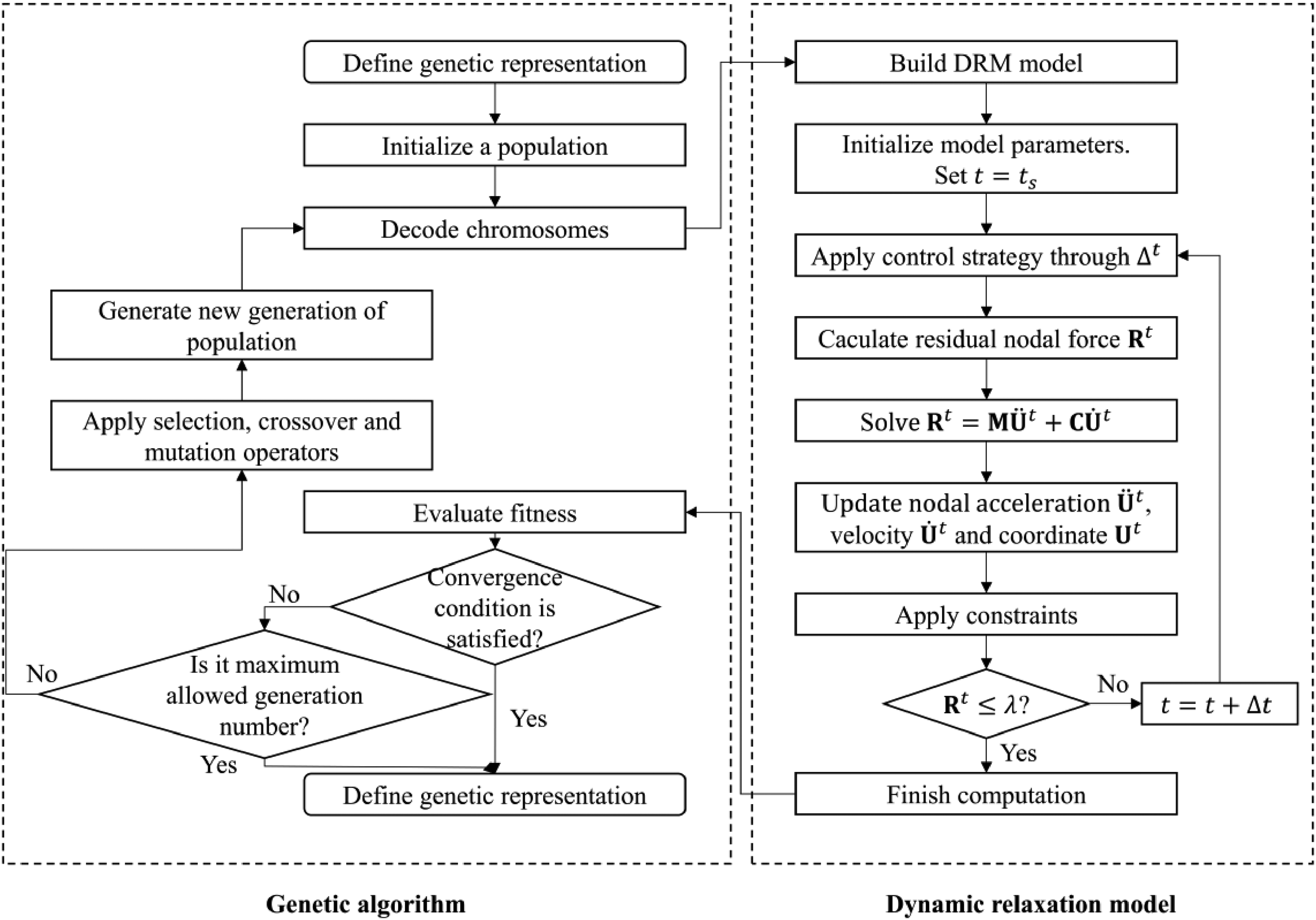
Flow chart of optimization searching of rolling gaits.
A 6-strut tensegrity robot with membranes
A 6-strut tensegrity robot with membranes (Figure 3) is composed of 12 nodes, six compression bars, 24 tendons, and eight membranes. The prefix “A” is used to label six struts in Figure 3(a). According to the previous work's definition, 35 the tensegrity robot is composed of two types of surface triangles: closed triangles (TC) containing three tendon edges for each and open triangles (TO) containing two tendon edges for each. The number of triangles is listed in Table 1. Each TC has a membrane, which can be used for pasting solar cells. Figure 3 illustrates the two basic forms (TC base face state and TO base face state) for the tensegrity robot, which can be used to classify different rolling gaits. Table 2 lists the assumed properties of the active struts, tendons, and membranes.

(a) TC base face sate for the 6-strut tensegrity robot with membranes, and (b) TO base face sate for the robot.
Number of surface triangles.

Properties of members.

The active struts are actuated at 5 mm/s, with an actuating range of [−4.00, +4.00] cm. Dynamic responses must be considered in this study and thus real values of the mass and damping are used here. The mass of the node is calculated by dividing the mass of members attaching to the node. The damping coefficient of material is set as 0.01 for the struts and cables, and it is set as 0.2 for the membranes according to the references.50,51 In addition, the stiffness damping factor is set as 0.0002 by using the frequency of the tensegrity robot (16.96 Hz) and the dynamic stiffness damping ratio (0.01). 44 The coefficient of friction is assumed as 0.5 and the contact stiffness with the virtual ground is assumed as 1000 N/m. Considering the weight of the control box, it is assumed that a mass of 127.6 g is applied to the nodes in the robot's center.
Rolling gaits
Effects of membrane on original gaits
The original rolling gaits are defined as the rolling actuating strategies designed for the 6-strut tensegrity robot without membranes by the method mentioned in Model and method section. The parameters of the GA used to get gaits in this study are set as follows: the population size is 50, the maximum generation is 50, and the generation gap and crossover rate are 0.8 and 0.7, respectively. Based on these results, several rolling gait primitives are discernible, as listed in Table 3. The start and final touching-ground triangles of a rolling gait primitive are represented in the table. As in the notation TC-6→TO-7, it describes a rolling gait from TC-6 to TO-7. This notation to describe rolling gaits is used in the entire article. Different rolling gait primitives can be realized using different control strategies, and Table 3 provides the control strategies for different rolling gait primitives along with the related traveling distances and the numbers of rolls.
Original rolling gaits of the tensegrity robot without membranes. a

Positive and negative actuation lengths indicate elongation and shortening, respectively.
In order to study the effects of the membranes, the obtained original gaits are applied to the 6-strut spherical tensegrity robot with membranes. This study primarily focuses on examining the influence of the relative stiffness between membranes and tendons on the suitability and traveling distance of the original gaits of the tensegrity without membranes. The relative stiffness between membranes and tendons is defined as:
Computations using different values of the relative stiffness between membranes and tendons are conducted. The prestress in the membrane is set as the same in Table 2. As shown in Figure 4, for the systems with relative stiffness equal to or more than 1.8, some original gaits are inapplicable. Particularly, all TC-TO gaits are infeasible for the systems with relative stiffness equal to or more than 2.4. For the TO-TC gaits, the number of rolls of gait 4 and gait 5 is only one when the system has a relative stiffness equal to or more than 2.4. For the system with a relative stiffness equal to or less than 1.2, all the original gaits are applicable. In addition, compared to the cases without adding membranes, it is observed from Table 4 that most of the moving displacements of the system are reduced after adding the membranes. Moreover, as the relative stiffness increases, the reduction becomes larger. For the system with a relative stiffness of 4.8, the average reduction rate reaches 18.98%, which is not negligible. In conjunction with the findings presented in Figure 4, it is found that as the relative stiffness of the system decreases, the influence of the membranes on the success rate and traveling distances of the original gaits diminishes. Furthermore, these effects become negligible when the relative stiffness of the system equals or falls below 1.2.

Influence of the relative stiffness on the count of rolling.
Influence of the relative stiffness on the traveling distance of the original gait. a

The relative stiffness of 0 represents the tensegrity system without membranes. “–” in the traveling distance column represents the rolling gait is unfeasible.
Redesigned rolling gaits
As stated in “A 6-strut tensegrity robot with membranes” section, the tendons have a stiffness of 150 N/m and membranes have an elastic modulus of 2.4 MPa with a thickness of 0.3 mm. Consequently, these values yield a relative stiffness of the system equal to 4.8. According to the results in the above section, the influence of the membranes cannot be ignored. Due to the inapplicability of some original gaits, it is necessary to redesign the rolling gaits of the tensegrity with membranes by using the approach presented in “A 6-strut tensegrity robot with membranes” section. The parameters of the GA and the properties of the members are set the same as those in the previous section.
As shown in Figure 5, it is observed that gaits completing once-rolling locomotion with a centroid displacement of around 0.06 m are found in the 10th generation for the system without membranes in the TC state. But for the system with membranes, gaits completing once-rolling locomotion are not found until the 39th generation (Figure 5(a)). Meanwhile, the traveling distances of the found rolling gaits are smaller than that of the system without membranes. The gaits completing once-rolling locomotion with a centroid displacement of around 0.06 m are found in the first generation for both types of systems in the TO state. Besides, for the system without membranes, the gaits completing twice-rolling locomotion with a centroid displacement of around 0.12 m were found in the 19th generation, but they cannot be found for the system with membranes within 40 generations (Figure 5(b)). This indicates that the TC-step gaits are harder to identified for both types of systems and the maximum traveling distance achieved is smaller than that achieved by the TO- step gaits. Furthermore, the findings indicate that the identification of suitable rolling actuating strategies for the system with membranes is comparatively more challenging than for the system without membranes. Additionally, the maximum achieved traveling distance of the system with membranes is inferior to that of the system without membranes.

Fitness versus generation: (a) TC base face sate; (b) TC base face sate.
Several rolling gait primitives, as listed in Table 5, can be identified from the redesigned results. The rolling gaits from TC to adjacent TOs and from TO to adjacent TCs all can be found, but the gaits completing twice-rolling cannot be identified. For the system with a relative stiffness of 4.8, four of seven original gaits in Table 3 are inapplicable, but the redesigned rolling gait primitives enable the tensegrity structure with membranes to transition from TC to TOs, and vice versa, showcasing the enhanced applicability of the redesigned rolling gaits.
Redesigned rolling gaits of the tensegrity robot with membranes. a

Positive and negative actuation lengths indicate elongation and shortening, respectively.
The motion process of the redesigned rolling gaits for the system with membranes is examined detailly. In the redesigned gait 1, for example, the robot rolls from TC-6 (3, 7, 12) to TO-5 (3, 11, 12). The projections of typical nodes and centroid of the robot are shown in Figure 6(a). It can be seen that the tendon between nodes 3 and 12 serves as the rolling axis. Since the friction force between the system and the ground cannot balance the force caused by the system, the nodes that touch the ground move. The displacement of node 3 is around 1.0 cm, and the displacement of node 12 is quite tiny. This implies that the rolling axis moves during rolling. In the redesigned gait 4, the system rolls from TO-5 (3, 11, 12) to TC-5 (3, 6, 11). The projections of typical nodes and centroid of the tensegrity with membranes are shown in Figure 6(b). It can be seen that the tendon between nodes 3 and 11 serves as the rolling axis. The displacements of node 3 and node 11 are around 2.1 and 0.7 cm, respectively, which are not ignorable as well. This implies that the rolling axis also moves during the gait. Based on the analysis, it is concluded that all redesigned rolling gaits of the tensegrity structure with membranes involve the system rolling around a moving axis; conversely, rolling gaits revolving around a fixed axis could not be identified or observed.

Projection of typical nodes and centroid of the tensegrity robot with membranes rolling in redesigned (a) gait 1 and (b) gait 4.
Experiments
Physical prototype
To physically demonstrate and validate the obtained rolling gaits, we manufactured a prototype of the tensegrity robot with membranes (Figure 7(a)). The parameters of the materials used in the robot are identical to those listed in Table 2. Six active struts are servo linear actuators with an initial length of 15.6 cm and an extensible length of 10.0 cm. They change to 20 cm at their working state. Twenty-four rubber ropes with a stiffness of 150 N/m and an initial length of 6.0 cm are used as tendons. Due to the large deformations of the membranes during movement, the membrane material needs a small modulus of elasticity and high resilience. In this study, PDMS films are used. They have an elastic modulus of 2.4 MPa, a thickness of 0.3 mm, a density of 1000 kg/m3, and an initial length of the triangle sides of 11.0 cm. For illustration, the material of a membrane is marked in yellow in the figure. The actuators, rubber ropes, and PDMS films are connected with 3D printed nodes, and every two films are connected to a node with a nylon rivet, as shown in Figure 7(b). A control box containing a Bluetooth communication module, a servo control module, and a lithium battery is placed in the center of the robot by 24 rubber ropes that are the same as those used for tendons. The total weight of the hardware robot is 724.2 g. A control program on a PC can wirelessly control the robot through Bluetooth communication.
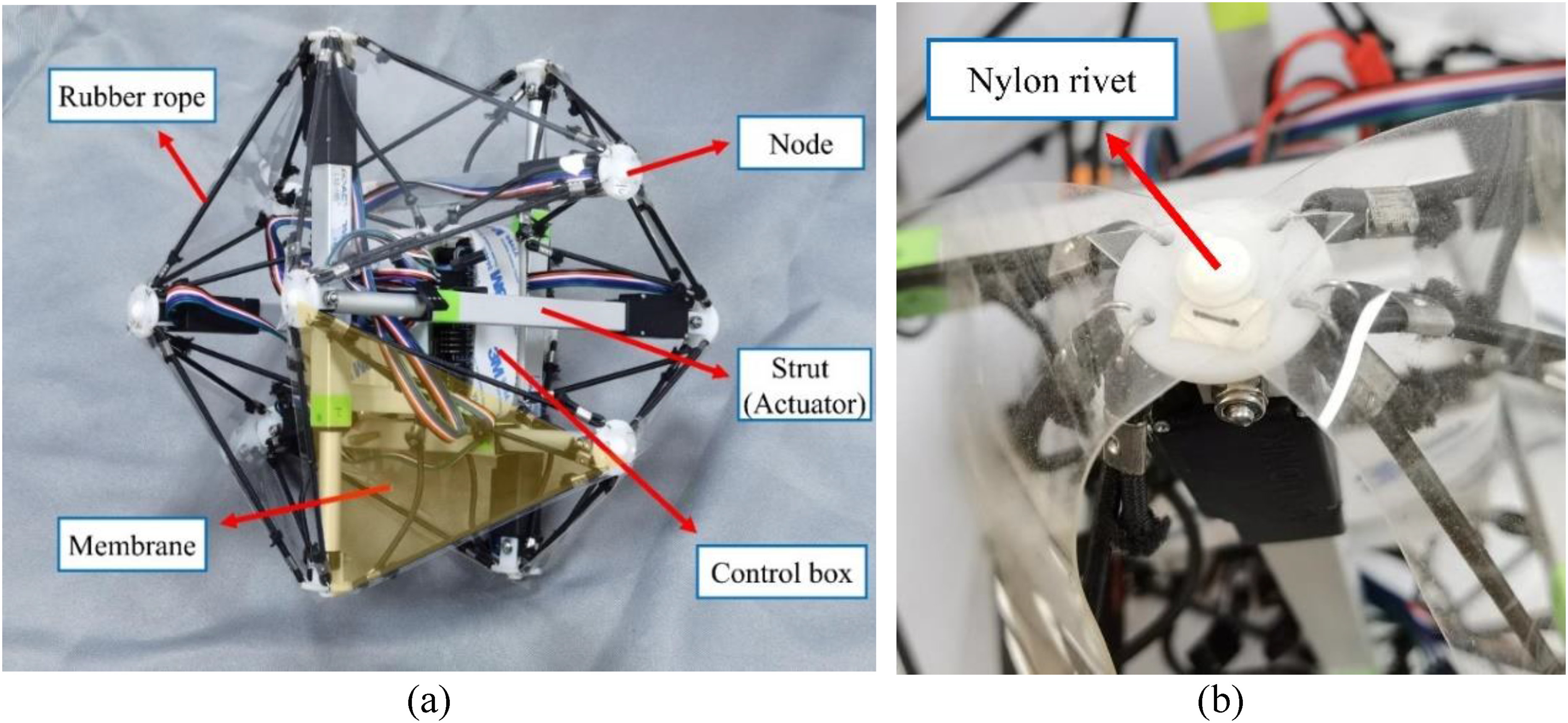
Physical prototype of the tensegrity robot with membranes: (a) work state and (b) joint construction.
Validation of rolling gaits
To verify the proposed model and method, experiments about redesigned rolling gaits on the 6-strut tensegrity robot with membranes are carried out. The results of these tests are shown in Table 6. Based on the experimental results, the physical prototype successfully demonstrates four out of the five redesigned gaits. These outcomes indicate a high experimental success rate for the implemented redesigned gaits.
Test results of the redesigned rolling gaits. a

In the “feasible” column, a successful gait is recorded as “Yes” and an unsuccessful gait is recorded as “No.”
Different stages of a redesigned step are observed. A complete rolling process includes initial state, deformation, rotation, and recovery. Two types of redesigned gaits are applied to the robot for the experiment, where redesigned gait 1 in Table 6 is taken as a case of TC-TO gaits (Figure 8(a)), and redesigned gait 4 is taken as a case of TO-TC gaits (Figure 8(b)). Recall the numerical traveling distances are 5.44 and 5.29 cm for redesigned gait 1 and gait 4, respectively. As shown in Figure 8, it can be observed that nodes 3 and 11 have significant displacements in redesigned gait 1, which leads to an obvious movement of the tendon between nodes 3 and 12. This phenomenon is the same as the simulation in Rolling gaits section. Meanwhile, the traveling distance measured in the experiment is 6.12 cm, and the relative error between the experimental results and simulation results is 12.4%. Notable movement of nodes 3 and 11 in redesigned gait 4 can be observed, which means that the tendon between nodes 3 and 11 also moves. The traveling distance is 6.24 cm, and the difference between measured and calculated traveling distances is 18.0%.

Experimental observation on different stages of a step: (a) TC-TO and (b) TO-TC.
It can be observed that the gait-generating algorithm is generally effective and the redesigned gaits have a high success ratio in experimental results. However, the difference between measured and calculated traveling distances is distinct. The main reasons are as follows. First, many details of the tensegrity robot are not considered in the idealized numerical model of the robot; for example, in the physical model, the control box is not completely at the center of the structure, but the central concentrated load is simplified as a node with mass in the numerical model. The struts in the physical prototype are bars with uneven mass distribution, but the mass of the struts is assumed to be uniform in the numerical model. Second, during the control process, there may be some deviation between the actual drive quantity and the target drive quantity of the actuators.
Conclusions
In this work, a mathematical model for the locomotive tensegrity with membranes is developed and an algorithm incorporating a GA with a DRM is used to generate rolling gaits for the locomotive tensegrity. A strut-actuated 6-strut tensegrity with eight membranes covering its surface is taken as a typical example of locomotive tensegrity with membranes. The influence of the relative stiffness between membrane and tendon on the rolling gaits of the locomotive tensegrity is investigated. A physical prototype of the 6-strut locomotive tensegrity is fabricated and tested. The numerical and experimental results demonstrate that: (a) the incorporation of membranes will affect the success rate and traveling distances of the original gaits of the tensegrity without membranes; (b) for the systems in which the effect of the membranes cannot be ignored, the generation of a suitable rolling gait is more difficult for the system with membranes and the traveling distance of the gait achieved is smaller than that of the system without membranes; (c) the redesigned gaits are more feasible for the systems with membranes, but the gaits with secondary rolling and fixed rolling axis cannot be found; and (d) the experiments conceptually validate the rolling actuating policies produced by the numerical method. However, the difference between the experimental and numerical results is nonignorable, due to the discrepancies between the physical prototype and numerical model.
In the future, the discrepancies between the numerical and experimental results can be reduced through the utilization of a more precise physical prototype. This improved prototype would aim to mitigate the impact of variations in the mass distribution of the control box and actuators. Enhancing the analytical model by incorporating advanced membrane units would contribute to further accuracy in the predictions. Besides, learning-based or data-driven approaches52,53 could be used to enhance the efficiency of the gait-generating process and enhance the optimization of the generated gaits.
Supplemental Material
Supplemental Material
Footnotes
Acknowledgments
This work was supported by the National Natural Science Foundation of China (Grant Nos. 52178175 and 51908492) and the Natural Science Foundation of Zhejiang Province (Grant No. LZ23E08003).
Data availability
The data that support the findings of this study are available from the corresponding author upon reasonable request.
Declaration of conflicting interests
The authors declared no potential conflicts of interest with respect to the research, authorship, and/or publication of this article.
Funding
The authors disclosed receipt of the following financial support for the research, authorship, and/or publication of this article: This work was supported by the National Natural Science Foundation of China, Natural Science Foundation of Zhejiang Province (grant number numbers: 51908492, 52178175, and LZ23E08003).
Supplemental Material
All supplemental material mentioned in the text is available in the online version of the journal.
References
Supplementary Material
Please find the following supplemental material available below.
For Open Access articles published under a Creative Commons License, all supplemental material carries the same license as the article it is associated with.
For non-Open Access articles published, all supplemental material carries a non-exclusive license, and permission requests for re-use of supplemental material or any part of supplemental material shall be sent directly to the copyright owner as specified in the copyright notice associated with the article.