
Abstract
According to the grasping requirements for fragile workpieces with cylindrical inner walls, a manipulator with internal bracing has been designed. The manipulator utilizes a constant-speed push cylinder to drive the linkage mechanism and accomplish the related works. Considering the fragile nature of the workpieces, reducing the impact velocity between the manipulator finger and the workpiece is a primary objective in the mechanism design. To achieve this, an optimization design is carried out, which maintains the overall average speed of the manipulator, while reducing the average speed only during the contact between the finger and the workpiece. The goal of optimization is to minimize the impact velocity at the contact point, using the linkage structure parameters as variables. The genetic algorithm (GA) is employed for the optimization process. The results show that optimization reduces the impact velocity at the contact point by 44.80%. To gain further insight into the influence of the process, a finite element model of a finger grasping a fragile object was created using joint modeling with the SolidWorks, Hyper Mesh, and LS-DYNA software. Simulations reveal that, after optimization, the maximum internal stress of three workpieces with thicknesses of 2.00 mm, 1.00 mm, and 0.50 mm was reduced by 47.42%, 41.53%, and 44.20%, respectively. To study the general law of the mechanical hand grasping fragile workpieces, the relationship between the cylinder driving speed and the impact speed is established. Based on the simulation results of maximum contact impact velocity, workpiece wall thickness, and maximum contact force, a prediction model of workpiece internal force is established using the Kriging prediction model theory. Additionally, the feasible range of grasping parameters under different wall thickness conditions is determined and discussed. The reliability of the designed structure is experimentally verified, providing valuable insights for ensuring the lifting work reliability of manipulators handling fragile workpieces.
Keywords
Introduction
Fragile materials undergo minimal elastic deformation from damage to fracture under force and do not exhibit plastic deformation. As a result, their ultimate strength typically does not surpass the elastic limit. Fragile materials exhibit poor resistance to dynamic loads or impacts and have significantly lower tensile capacity than their compressive capacity, making them inherently fragile. Examples of fragile materials include glass and ceramics, which find extensive applications in non-metal material processing, food packaging, production, and various logistics-related industries. Consequently, there is a high demand for manipulators capable of grasping and handling fragile workpieces in these fields.1,2
In the production process of synthetic diamonds, pyrophyllite blocks are utilized as a material to synthesize artificial diamonds. Both raw materials and finished products of pyrophyllite blocks are fragile. 3 However, due to the high-intensity and repetitive nature of pyrophyllite block production, it becomes challenging to attract new workers. Manipulators are required to grasp and transfer these fragile pieces while meeting the high-speed operation demands of the production process.
Figure 1 illustrates the production process of pyrophyllite blocks. First, a fragile raw material ring (Figure 1(a)) is transferred above the external mold (Figure 1(b)). Second, the raw material ring is assembled in the terrace die (Figure 1(c)). Third, to produce a finished block (Figure 1(d)), a certain amount of raw powder is added to the gap between the external mold and the terrace die. The press head is utilized to compress the powders and raw material ring. Subsequently, the bottom die pushes out the finished block (Figure 1(e)). Finally, the finished block (Figure 1(f)) is grasped and transferred to the working position.
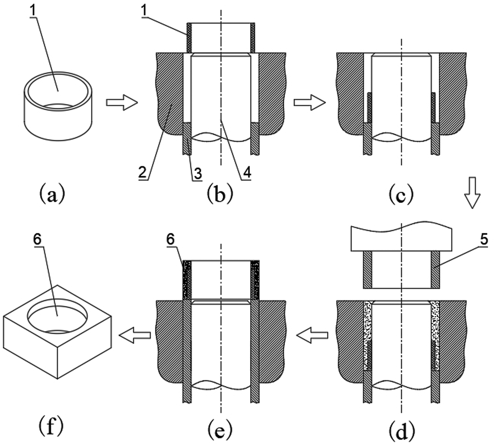
Pyrophyllite block production process. 1. Raw material ring; 2. External mold; 3. Bottom mold; 4. Terrace dies; 5. Press head; 6. Finished block.
In the production of pyrophyllite blocks, the grasping and transferring of workpieces are typically performed manually by workers using both hands. However, the development of a manipulator system can greatly enhance operation efficiency.
A multitude of companies around the globe have developed robotic systems for the loading and unloading operations of robots, which are employed in production lines. In 2021, ABB released the industrial collaborative robot CRB1100, which is used in conjunction with the Omni Core robotics controller to minimize the risk of contact between the operator and the high-speed moving robot. Furthermore, numerous industrial robot brands, including those produced by KUKA in Germany, FANUC in Japan, Kawasaki, and others, have been employed in a multitude of large-scale and high-product-quality applications within the field of parts processing, such as automotive manufacturing, packaging, and other production line equipment.4,5
The end-effector is a critical component of manipulator systems as it enables specific grasping functions. The design scheme for the end-effector primarily involves a multi-link mechanism driven by a motor or cylinder. Such end-effectors are commonly utilized in the handling operations within industrial production lines. There are several well-known existing structures, 6 including the pneumatic gripper from the German FESTO company, the pneumatic parallel claw gripper from SCHUNK, the pneumatic finger gripper from GIMATIC, and the finger cylinder from TAC. These pneumatic grippers require the assistance of a sophisticated control system. In the context of high-speed work gripping, while it is possible to control the gripping speed of the hand claw by adjusting the air pressure, high-speed gripping inevitably produces impact stress. For example, in the case of gripping thin-walled, fragile products, such as the original processed product of synthetic diamond, the pyrophyllite ring, the high impact stress will cause damage to the product.
While the majority of end-effectors are designed with single and stable motions for specific grasping tasks, they frequently encounter limitations in terms of working conditions and flexibility. Factors such as object deformation and environmental interference can impede these end-effectors from achieving accurate grasping. 7 In general, there are multiple approaches to grasping a workpiece, and using fingertips for precise grasping is a potential solution. 8 Scholars have explored interaction models between fingers and grasped workpieces, offering new insights for designing innovative finger structures. Numerous researchers have conducted grasping analysis and research on different finger design schemes, including in-depth studies on grasping strategies, dynamic characteristics, and side grasping methods.9,10 For example, Babin et al. optimized a robotic gripper for grasping large and thin objects. 11 Watanabe et al. presented a novel small gripper capable of grasping various types of small-sized items. 12 Hirano et al. presented an underactuated gecko-inspired adhesive gripper capable of grasping a wide range of curved surfaces. 13 These studies contribute to the advancement of grasping techniques and the development of improved finger designs
In the domain of feeding manipulators and end-effectors, considerable advancements have been made by several researchers in fulfilling the precise grasping demands of workpieces. These advancements have been accomplished through the implementation of parallel manipulator configurations, series motion module configurations, and diverse end-effectors. Similar to the human hand, grippers possessing multiple fingers are deemed optimal for manipulating target objects. 14 However, with the increasing number of actuating components, the operation and control of multiple actuators pose challenges, including increased system complexity, load distribution challenges, and collision avoidance issues. Addressing these challenges requires comprehensive consideration of knowledge and techniques from various aspects such as mechanical design, control algorithms, and system integration to ensure the efficient operation of multi-actuator systems.15,16 Parallel grippers are frequently employed due to their simplicity and effectiveness. 17 Nevertheless, end-effectors and infeed manipulators that are suitable for the transfer and assembly of fragile parts are rarely involved in the production of pyrophyllite blocks.
When a manipulator grasps a fragile workpiece, the strength of the workpiece and the stress conditions impose limitations on the contact stress between them. The end-effectors of manipulators designed for grasping thin-walled fragile pieces encounter several major technical challenges. For instance, the impact between the manipulator finger and the workpiece during high-speed grasping can lead to workpiece facture. “Hard” exerting force during assembly processes can also result in the same problem. Therefore, it is of significant theoretical and practical value to investigate and address the technical issues faced by high-speed manipulator systems that are suitable for grasping and assembling thin-walled fragile parts.
Since grippers may cause damage to fragile objects, avoiding excessive contact forces between the gripper and the object has been a challenge for traditional rigid robot grippers. To overcome these challenges, several soft robotic grippers have been proposed.18–22 For the application of different forces, Koivikko et al. proposed a magnetically switchable soft suction gripper. 23 To grip fragile objects with complex shapes, Lee et al. presented a universal soft gripper with shape-adaptive ability. 24 However, these grippers are limited to grasping lightweight workpieces and possess only a singular grasping capability. When faced with the demands of high-speed grasping and assembly tasks, their operational efficiency significantly diminishes.
The purpose of this paper is to address the transfer and assembly challenges of pyrophyllite material workpieces in the efficient production of synthetic diamond raw products, and design a gripping and pressing integrated manipulator. 25 However, the research on the gripper mainly focuses on the impact damage to the workpiece caused by the finger structure of the manipulator and the optimization of grasping parameters,26,27 and the analysis of the gripper transmission parameters is lacking. During high-speed grasping operations, excessively high gripping speeds will inevitably generate elevated impact stresses, leading to the fragmentation of fragile workpieces. To meet the requirements of the high-speed grab of fragile workpieces by the manipulator while ensuring the integrity of the workpieces, this paper aims to enhance the contact performance between the manipulator's claw and the workpiece by optimizing the parameters of the transmission mechanism. Specifically, the objective is to reduce the impact velocity of the manipulator's claw as it approaches the workpiece surface by adjusting the acceleration at the fingertips while maintaining a constant average speed during high-speed workpiece grasping operations and to study the variation law of the stress as the manipulator grabs the workpiece.
The transmission mechanism of the manipulator is a linkage mechanism, and the optimization design of this mechanism is a well-established research topic. 28 To minimize the impact during the finger-grasping process, an optimization design of the transmission mechanism is conducted. The main objective of this optimization is to reduce the average speed of the gripper on the contact segment, as well as the instantaneous impact velocity when the gripper grasps the workpiece. To achieve this, the optimization model is based on genetic algorithms (GAs), which simulate the natural selection and evolution of species. GAs have been widely applied in various fields of system optimization due to their effectiveness, especially for problems that are difficult to solve using traditional differentiation methods.29,30 Furthermore, evolutionary theory has also been employed to address optimization problems. 31
To investigate the potential fracture problem caused by the collision between the fingers of the manipulator and the fragile parts, this paper also carried out a simulation study of the manipulator gripping fragile workpieces. The objective was to assess whether the contact impacts during gripping and the internal stresses during the manipulator gripping of the workpieces were destructive to the workpieces.
Aiming at building prediction models, several scholars have carried out relevant studies: for instance, Peng 32 utilized the Kriging model to optimize and correct old Bridges. Wenzhu et al. 33 introduced the Kriging agent model to enhance the stability design of drum brakes. Zeming et al. 34 proposed a two-layer agent model based on NARX and Kriging. In this model, the Kriging model is updated by selecting the best sample points and incorporating them into the initial sample points. In this study, the Kriging agent model was established to predict the contact stress under different conditions of wall thickness and grasping speed. The research process serves as a foundation for improving the finger structure and determining the optimal working process parameters.
The remaining sections of the paper are organized as follows: the proposed manipulator structure is briefly introduced in Section “Proposed manipulator structure.” The modeling and analysis of the finger motion are performed in Section “Finger motion model.” The parameter optimization process for the finger transmission mechanism is described in Section “GA-based parameter optimization model for the manipulator mechanism.” The simulation analysis of contact impact is conducted in Section “Impact simulation analysis.” The grasping law of the manipulator is studied in Section “Research on grasping law of manipulator.” Experimental validation is carried out in Section “Experimental validation.” Finally, conclusions are drawn in Section “Conclusion.”
Proposed manipulator structure
In this section, motion characteristics of a downward pressing action simulating the human hand are investigated. When a human grasps a circular object with internal bracing, the shape of the fingers is grounded into a cylinder (Figure 2).
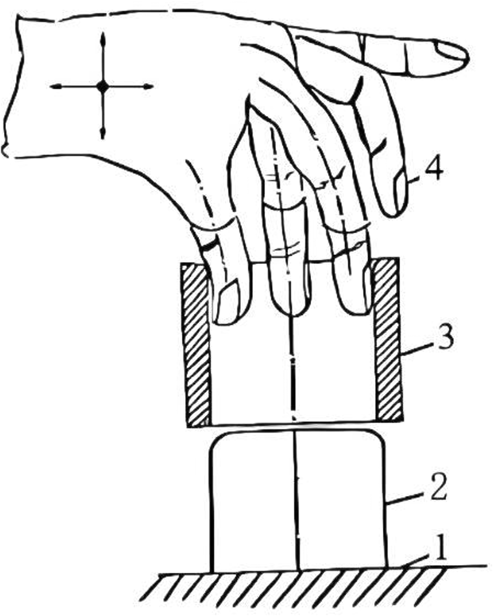
Motion characteristics of human fingers assembling circular objects. 1. Workbench; 2. Cylindrical object; 3. Circular object; 4. Finger.
A circular arc three-finger model with internal bracing is designed to achieve the grasping and transferring actions for concrete structures. The movements of the fingers in two directions are driven by two linear actuators that are directly connected. The opening and closing movements of the fingers are achieved by the actuator's linear output motion, through a linkage mechanism.
To meet the operational requirements of the press used in the production of pyrophyllite blocks in the artificial diamond industry, a manipulator system configuration specifically designed for grasping and assembling fragile raw material rings has been developed (refer to Figure 3).

Manipulator system for the production of pyrophyllite blocks. 1. Press racks; 2. Module for vertical motion; 3. Module for horizontal motion; 4. Palm; 5. The mounting base of the finger; 6. Spring; 7. Guide rod; 8. Finger motion actuator; 9. Piston rod; 10. Finger connecting rod; 11. Finger transmission rod;12. Finger body; 13. Rubber pad; 14. Finger motion controller; 15. Horizontal motion controller; 16. Vertical motion controller; 17. Master controller.
To grasp, transfer, and assemble objects, a cylinder palm has been designed, with circular-arc three fingers featuring an internal brace nested within the inner cylinder of the palm. A guide rod and a spring are positioned between the palm and the mounting base of the fingers. According to the desired process, the mounting base of the fingers can move vertically within the palm and return to its original position due to the spring effect. The manipulator system's overall movement is facilitated by the horizontal and vertical motion modules.
The design of the finger actuator plays a crucial role in ensuring the stability of the manipulator's grasping operation. During the grasping process, it is essential to control the contact force between the finger and the fragile thin-walled raw material ring to prevent any potential fractures or damage to the workpiece. This control over the contact force is crucial for maintaining the integrity of the workpiece during the operation.
The hand structure, or a specific part of the manipulator as shown in Figure 4, has been designed to meet the requirements of grasping and transferring fragile workpieces as depicted in Figure 1. The main characteristics of this structure are as follows: The cylindrical palm imitates the shape of a human palm, providing a suitable form for grasping. The circular arc three-claw fingers are covered with a soft rubber material, resembling the texture of a finger pad. This helps in achieving a secure grip on the workpiece. The structure incorporates an elastic connection between the palm and the fingers, allowing for significant relative displacement motion. The circular arc of three fingers is driven by air pressure. When the three fingers release the object and remain stationary, the cylindrical palm can perform a downward pressing action driven by the vertical motion module. This action presses the circular object against a fixed fitting part. Once the downward pressing process is completed, the three-claw fingers retract and hide within the cylindrical palm. After the pressing action, the three-claw fingers can be ejected from the cylindrical palm due to the spring action. This design enables the manipulator to grasp fragile workpieces, carry out pressing actions, and release the workpiece effectively.
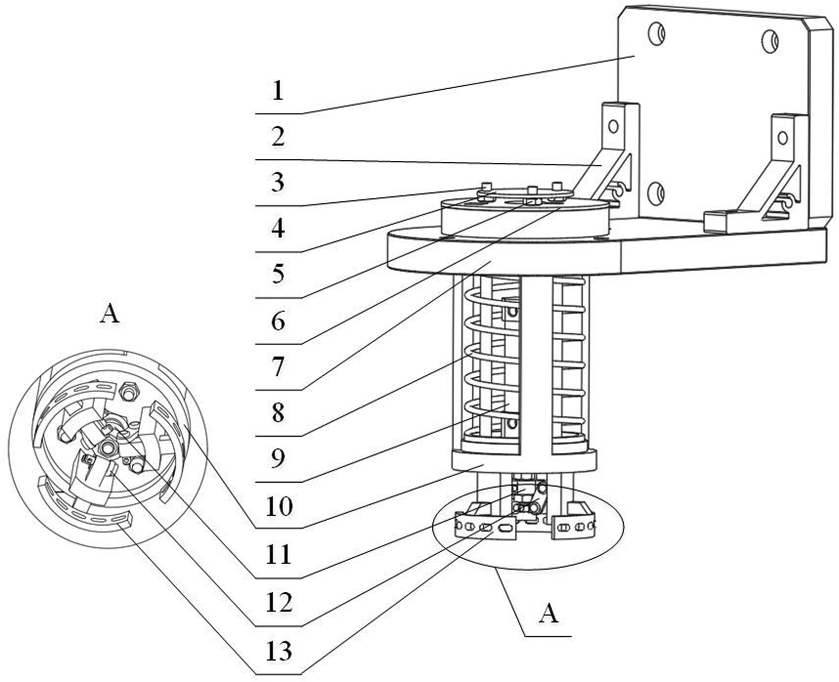
Manipulator structure. 1. Fixed plate; 2. Support frame; 3. Guide rod; 4. Connecting gasket; 5. Positioning nuts; 6. Gasket; 7. Connecting plate; 8. Spring; 9. Cylinder; 10. Palm; 11. Finger connecting rod; 12. Finger transmission rod; 13. Arc finger body.
In the finger structure mentioned earlier, an isokinetic cylinder is utilized as the driver for the fingers. The configuration of the three fingers actuated by the constant-speed cylinder is depicted in Figure 5. The cylinder consists of a cylinder block and a piston rod, which are the main components of the cylinder mechanism. The manipulator is mainly used for clamping cylindrical thin-wall fragile parts. For lightweight internal hollow cylindrical workpieces can also be clamped, but it is necessary to consider that the clamping force can meet the requirements of the clamped workpiece.
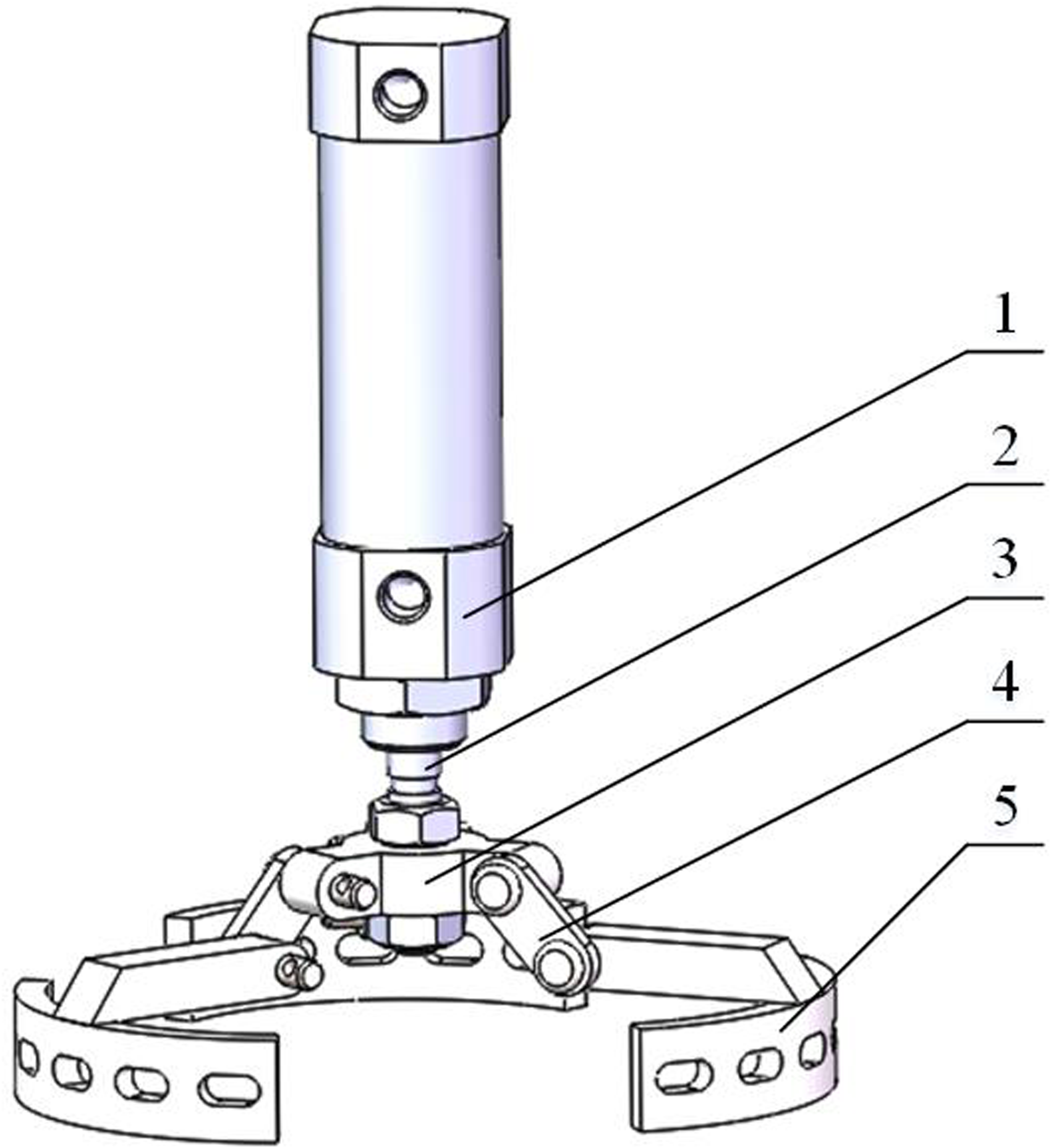
Finger structure actuated by a constant-speed cylinder. 1. Cylinder block; 2. Piston rod; 3. Finger connecting rod; 4. Finger transmission rod; 5. Arc finger body.
The actuator structure described above has a key objective of controlling the motion of the cylinder and achieving a constant speed output. The constant speed drive is achieved using air pressure. To ensure a stable air supply pressure, an outlet pressure is set up through a relief valve. This outlet pressure drives the air cylinder to move uniformly under static pressure, controlled by a precision electromagnetic valve. To monitor and regulate the system, a pressure sensor is employed to measure the outlet pressure of the electromagnetic valve. This outlet pressure is then fed back to a processor for further analysis and control. Additionally, the speed of the cylinder is measured by a speed sensor, providing feedback on the actual speed of the cylinder during motion. It is worth noting that during the motion of the cylinder, the air capacity within the cylinder undergoes constant changes.
To minimize driving pressure fluctuations, the control processor employs a composite control method known as Bang-Bang + K + PWM. This method is used to regulate the driving cavity pressure of the cylinder. The response process utilizes the Bang-Bang control method to rapidly bring the pressure to a steady-state region. In Bang-Bang control, the control system's state space is divided into two regions: one corresponding to the positive maximum value of the control variable and the other corresponding to the negative maximum value of the control variable. The switch surface, located near the interface between these two regions, causes the system output to fluctuate up and down. Pulse width modulation (PWM) is used to control the pulse width, which determines the desired waveform by adjusting the width of a series of pulse modulations. The output PWM pulse width signal controls the opening and closing of the electromagnetic microvalve, thereby regulating the pressure changes in the actuated chamber. Additionally, the classical proportional control method (K) is employed to improve control accuracy by adjusting the duty ratio of PWM. This allows for precise control over the average time of opening or closing the three-way microvalve, thereby enhancing the control accuracy of the actuated chamber pressure during steady-state operation and reducing pressure fluctuations. Once the pressure reaches a steady state, the K + PWM compound control method is utilized to further enhance steady-state accuracy and reduce pressure fluctuations. This compound pressure control scheme for the driving chamber of the cylinder is illustrated in Figure 6.
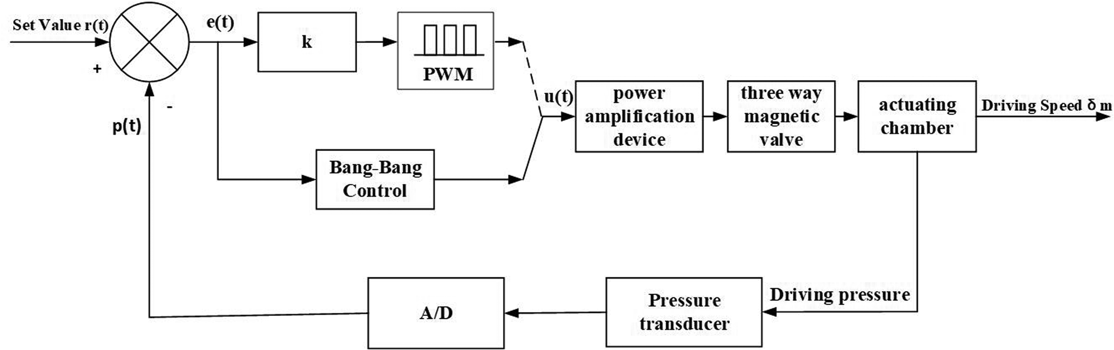
Driving pressure control block diagram based on the Bang-Bang + K + PWM method.
The error value is utilized to evaluate the response and steady-state processes of the system. When the absolute error exceeds 5.00% compared to the set value, it indicates a response process, and the system switches to the Bang-Bang control method. On the other hand, if the absolute error is less than or equal to 5.00% compared to the set value, the system response enters a stable state and automatically transitions to the K + PWM control method for regulating the driving chamber pressure of the cylinder.
The uniform motion control system block diagram for the cylinder drive is presented in Figure 7. The regulator ensures a stable air supply. The 3-way magnet valve, pressure sensor, and controller work together to finely adjust the driving pressure. The speed sensor continuously monitors the real-time movement of the cylinder, providing feedback to the controller. If the cylinder moves at a non-constant speed, the system performs appropriate adjustments to maintain control.

Control system block diagram for the isokinetic motion of the cylinder drive.
Finger motion model
The manipulator employs a constant-speed cylinder to drive both the transmission mechanism and the fingers. Figure 8 provides a sketch of the manipulator's motion, with the motion of the cylinder depicted as a slider.

Schematic illustration of the constant-speed cylinder and transmission mechanism motion.
The coordinate system xoy is depicted in Figure 8. L1 represents the distance between the drive ram and point B. L2, L3, L4, and L5 are the lengths of the connecting rods. L6 is the thickness of the rubber pad. L7 is the radius of the workpiece, which in this case is 27.75 mm. H0 is the distance between the drive ram and point O in the initial position.
The motion relationship of the transmission mechanism is established through the vector closed-loop (1) The initial position relationship is as depicted in Figure 8: (2) Kinematic analysis
For the
Driving slider 1 moves downward from its initial position, while its displacement is represented by


After substituting (3) Relationship among the motion parameters of constant-speed driver
If the motion of the cylinder is set as a constant-speed drive and the driving speed is denoted as


GA-based parameter optimization model for the manipulator mechanism
The optimization problem can be defined as searching for the mechanism parameters that maximize the objective performances and fulfill all the constraints.
Optimization model establishment
The motion trajectory and grasping performance of the manipulator that grasps fragile parts with internal bracing mode are as follows:
The overall motion time of the grasping action meets the requirements. The manipulator needs to operate at high speeds during most of the operation process to improve the operation efficiency. Nevertheless, the impact velocity of the manipulator action needs to be very small when the fingers contact the fragile workpiece to avoid the breakage of the workpiece. The motion speed of the fingers needs to be gradually reduced before the finger pad surface is nearly in contact with the fragile workpiece.
Optimization objectives determination
In the grasping process, the main objective is to reduce the impact velocity when the finger touches the workpiece. To simplify the objective function, three points are selected when the finger approaches the fragile part (Figure 8), that is the distances between points O and G are 27.50 mm, 27.00 mm, and 26.50 mm, respectively, while the objective function

After minimizing the
After substituting


Design Variable determination
The displacement, speed, and acceleration of the fingers are related to the structural parameters. The initial position H0 is determined based on the overall manipulator structure. The L6 parameter is determined by the thickness of the finger pad, here, L6 = 4.00 mm. The L5 parameter has little effect on finger motion velocity since the connecting rod “EF” and the overall manipulator structure are fixed, while it is set as L5 = 10.50 mm. L1, L2, L3, L4, and H0 are selected as the design variables:

Constraint determination
In the design scheme, the selection of each variable size is constrained by several conditions, including the kinematic characteristics of the mechanism, the coordination between the mechanisms, the technological level, the assembly conditions, and the overall design requirements of the manipulator. Specifically, these conditions include:
(1) Performance requirements
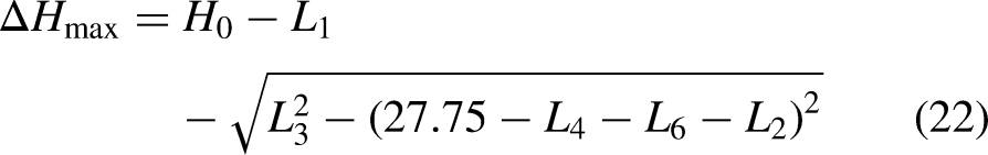
① The overall operating time cannot be increased. Based on the designed operating process of the manipulator, the grasping operating time is set as
By transforming Eq. (22), we obtain:


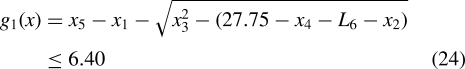
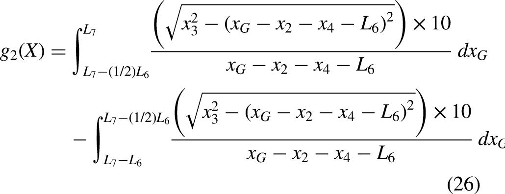
Subsequently, the constraint function ② When ③ Let ④ According to the initial design parameters, in the case, that a finger is in contact with the fragile workpiece, (2) Assembly conditions and boundary constraints ① Under the limitations of the fragile workpiece depth and the driving slider displacement, the variation range ② Restricted by the overall structure and the size of the gripped workpiece, the size of each connecting rod should satisfy the following constraints:
By transforming Eq. (25), we can obtain:
After transforming Eq. (30), we can obtain:
According to the structural constraints, the change ranges of the
This chapter defines the optimization problem as the parameter optimization of the mechanism using GAs, aiming to optimize the objective performance of the final combination structure, specifically to minimize the contact impact velocity while satisfying parameter constraints. In summary, since all objective functions are minimization objectives, a multi-objective optimization model for standard mechanical manipulator grasping impact velocity can be obtained:


Optimal design example and results analysis
(1) Initial parameter determination (2) Optimization process and results
After the preliminary design, the initial design parameters were determined. The structural parameters of the manipulator fingers are L1 = 20.80 mm, L2 = 4.26 mm, L3 = 8.90 mm, L4 = 10.70 mm, L5 = 10.50 mm, and L6 = 4.00 mm. The initial position H0 of the driving slider is set as 28.20 mm.
Based on the established optimization objectives, design variables, and constraint conditions, and in combination with the basic theory and process of GA, a corresponding program is implemented in MATLAB.
In this research, the optimization calculations are performed using the ‘x = ga (fun, nvars)’ function of MATLAB. The user-friendly interface of MATLAB greatly simplifies the programming process. The initial population of the manipulator optimization model is generated using a random generation method.
According to the optimization objective, design variables, and constraints established above, the parameters are given in combination with the basic theory of GA. The main initial parameters of the GA are shown in Table 1. After the GA solution is completed, the command window of MATLAB appears “Average in change the fitness value less than options function tolerance and constraint violation less than options constraint tolerance.” appears in the MATLAB command window.
GA initial parameters.

After conducting iterative calculations, the optimized results are listed in Table 2. The analysis of displacement, speed, and acceleration for point G on the finger is depicted in Figures 9–11, respectively. The curves are smooth both before and after the optimization. Furthermore, the trend of displacement changes in Figure 9 remains consistent before and after the optimization.

Displacement vs time analysis of the fingertip before and after the optimization.

Speed vs time analysis of the fingertip before and after the optimization.
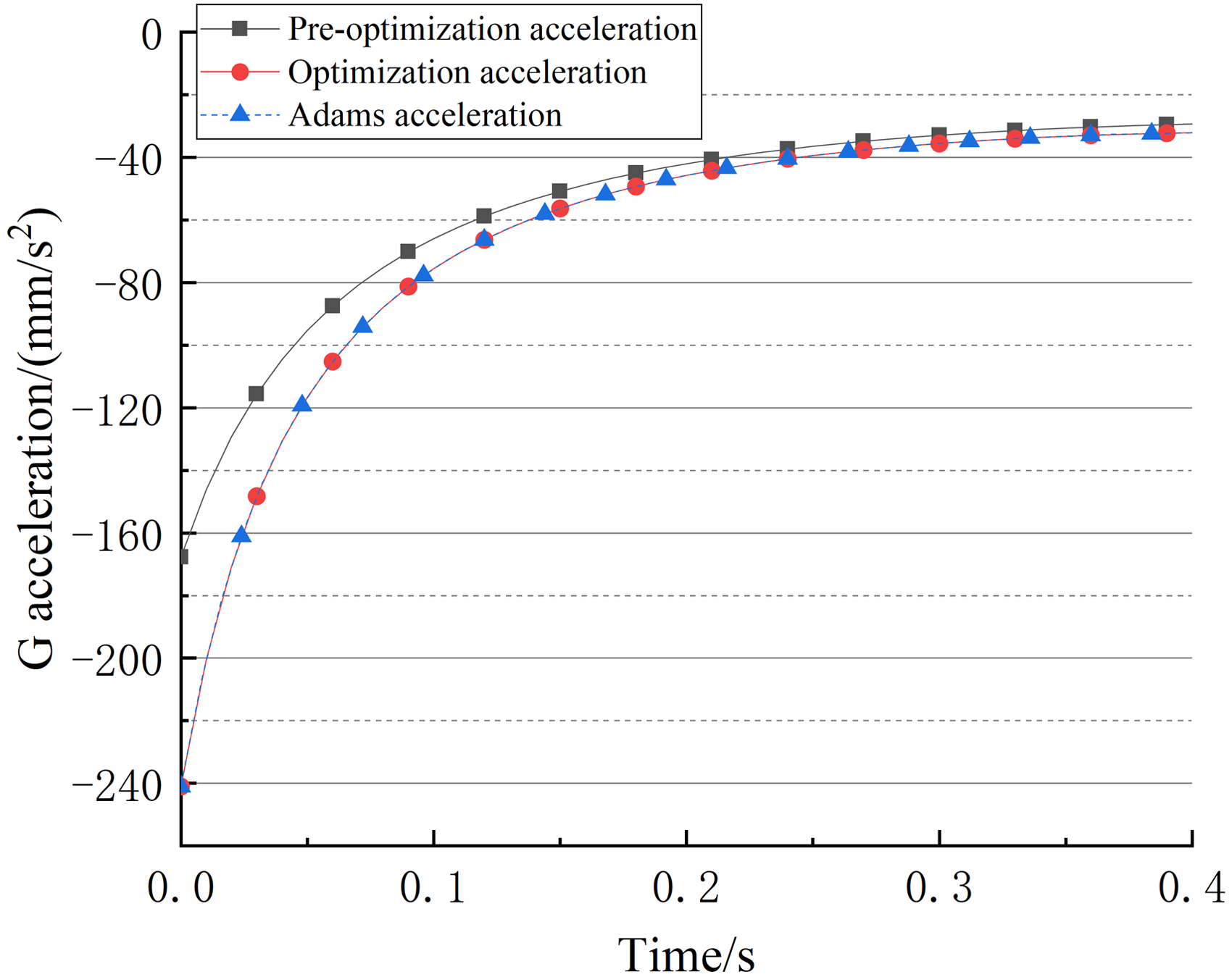
Acceleration vs time analysis of the fingertip before and after the optimization.
Parameter optimization before and after comparison.

Under the condition that the velocity of the cylinder driving slider was 16.00 mm/s, the initial speed of the fingertip increased from 23.90 mm/s to 27.00 mm/s, representing an increase of approximately 13.00%. When the fingertip meets fragile parts, the speed of the fingertip is reduced from 1.81 mm/s to 1 mm/s, representing a decrease of approximately 44.75%. The initial acceleration of the optimized fingertip increased by 44.00% from 167.73 mm/s2 to 241.05 mm/s2. As the fingers approach the fragile parts, both the velocity and acceleration are significantly reduced. Therefore, the velocity during the motion of the front section of the fingers was increased, while the velocity during contact with the fragile workpiece was reduced. After optimization, the impact velocity of the contact section for the finger motion was reduced by 0.80 mm/s (44.80%), while the overall movement time did not increase. Overall, the optimized manipulator motion satisfies the target requirements.
(3) Simulation based on ADAMS
The 3D model of the mechanism is established and imported into ADAMS for motion simulation using the optimized parameters. The material properties in Table 3 are added to each component, with the rubber pad and workpiece designated as flexible and the aluminum alloy component set as a rigid part. The inner radius of the workpiece is 27.75 mm, the wall thickness is 3 mm, and the height is 25 mm. A rotating pair is then added to each connecting rod joint, a moving pair is added to L1 and L4, and a contact property is added between the rubber pad and the workpiece. The driving is set as the moving pair at L1, with a speed of 16.00 mm/s and a driving time of 0.4 s. The simulation results are shown in Figure 12. The manipulator can grasp the workpiece smoothly. Figures 9, 10, and 11, respectively, give the simulation results of the displacement, velocity, and acceleration of the G-point of the claw. The outcomes align with the theoretical calculations, thereby validating the precision of the theoretical model.
Motion simulation model developed on ADAMS.
Material parameters.

Impact simulation analysis
The impact velocity of the finger plays a crucial role in determining the internal stress when it meets fragile parts. If the internal impact stress exceeds the allowable safety margin, it can destroy the fragile workpiece. Therefore, considering the change in contact impact velocity before and after optimization, the velocity that affects the internal stress during the grasping process is simulated and analyzed.
Material characteristic analysis
In general, fragile materials exhibit high compressive and shear strength, but relatively weak tensile strength.
35
According to the maximum tensile stress theory (also known as the first strength theory), the primary reason for the fracture of fragile materials under tension is the maximum tensile stress. Fragile materials break when the maximum tensile stress reaches a certain limit under any stress condition.
36
Specifically, fracture only happens when the maximum tension stress (
The impact stress occurs now of contact. Under high-speed impact, when the impact stress reaches the ultimate fracture strength (
In the simulation study, considering the time-dependent mechanical properties of the pyrophyllite ring, a stable and typical fragile material, such as glass, was chosen to replace the pyrophyllite as the research object. 38 Specifically, a glass ring with an inner radius of 27.75 mm, an outer radius of 30.75 mm, a depth of 35.00 mm, and a mass of 3.20e−3 kg was used as an example for grasping the fragile workpiece
Joint modeling and simulation
Using SolidWorks, HyperMesh, and LS-DYNA software for joint modeling, we established a finite element model for the finger used in grasping fragile workpieces, as shown in Figure 13. The manipulator consists of a rigid finger body and a flexible finger pad. The finger body is made of aluminum alloy material, while the surface of the finger is covered with a rubber material. The rubber pad is bonded to the surface of the mechanical finger.

Finite element model of the grasping impact-fragile workpiece.
Material model and parameter selection
The damage of fragile materials such as glass can be simulated using the Johnson-Holmquist plastic damage model, namely *MAT_JOHNSON_HOLMQUIST_CERAMICS (110# material) model, which includes the effect of damage on the strength of the remaining material during the compression process and the resultant expansion. The model also describes the relevant equations of the material response. The model is ideal for simulating the impact on fragile parts with parameters of strain rate, pressure, and impact effect. 39
The material parameters of glass are experimentally obtained using the Johnson-Holmquist ceramic material model, 40 while the detailed parameters are listed in Table 4.
Material parameters of the glass.

The material model *MAT_PIECEWAISE_LINER_PLASTICITY Material Constants (24#) was utilized to model aluminum alloy. The material parameters of the aluminum alloy selected for the finger are listed in Table 5. The material parameters of the rubber are listed in Table 6. The symbol A is an intact normalized strength parameter and B is a fractured normalized strength parameter.
Material parameters of the aluminum alloy.

Material parameters of the rubber.

Hourglass control and contact models
To minimize the computation time for the finger colliding with the fragile workpiece in LS-DYNA, the integral solution method chosen was the single-point integration method. However, when using a material model that adopts the *SECTION_SOLID implicit solid element type, the occurrence of zero-energy modes, known as the hourglass phenomenon, can lead to a zigzag deformation of the structural mesh, thereby affecting the simulation accuracy. The hourglass phenomenon is accompanied by the generation of hourglass energy. If the proportion of hourglass energy in the total internal energy is less than 10.00%, its impact on the calculation results will be minimal. If high simulation accuracy is required, the hourglass energy must not exceed 5.00% of the total internal energy.41,42
In LS-DYNA, it is necessary to define a contact model when two objects collide to prevent penetration between the contact surfaces. LS-DYNA provides a total of 22 contact types/models. In the grasping process, the contact between the finger and the workpiece involves a face-to-face interaction. Therefore, the AUTOMATIC_SURFACE_TO_SURFACE contact model is chosen, while the contact algorithm adopts the penalty function method. The friction coefficients for the contact include the dynamic friction coefficient, exponential attenuation coefficient, and static friction coefficient, which are related to the relative velocity of the contact surface. For a detailed explanation of the selection process, please refer to Ref. 43
Boundary conditions
To simulate the fixed workpiece, a full constraint was applied to the fragile workpiece. The finger surface was covered with a rubber plate, which had a thickness of 4.00 mm. The finger was positioned horizontally on the surface of the workpiece, with 3.00 mm between the finger and the workpiece Inner surface. To replicate the scenario where the finger grasps the workpiece, the workpiece was subjected to an end impact velocity of 1.81 mm/s (before optimization) and 1.00 mm/s (after optimization).
Simulation analysis results
The manipulator grasps the workpiece at an end impact speed of 1.81 mm/s (before optimization) and 1.00 mm/s (after optimization). The changes in the internal stress of the workpiece are exhibited in Figures 14 and 15, while the internal stress values are listed in Table 7.
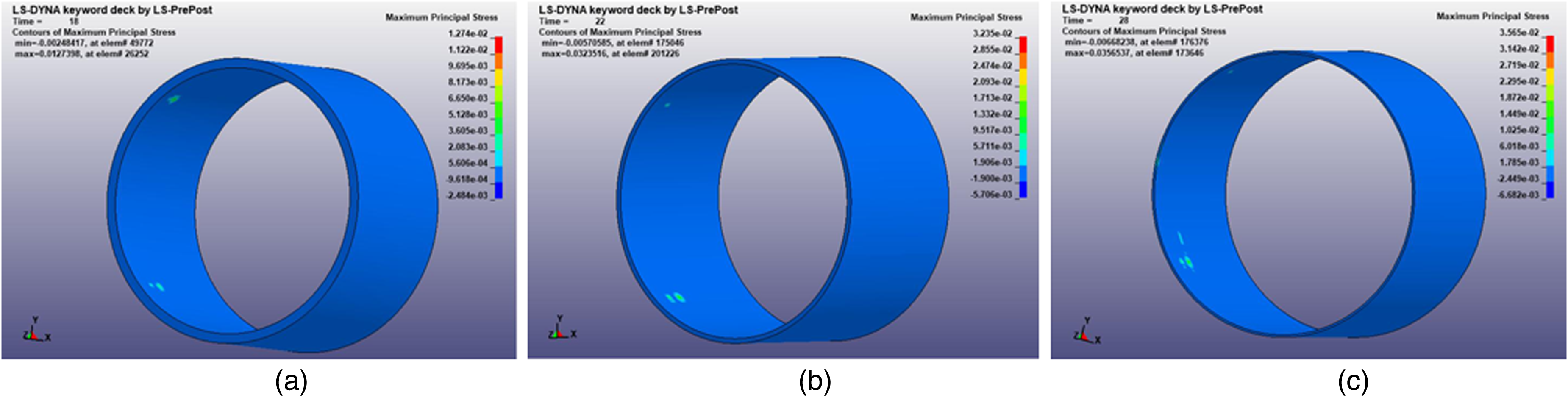
Simulation analysis results before optimization. (a) 2.00 mm thickness. (b) 1.00 mm thickness. (c) 0.50 mm thickness.
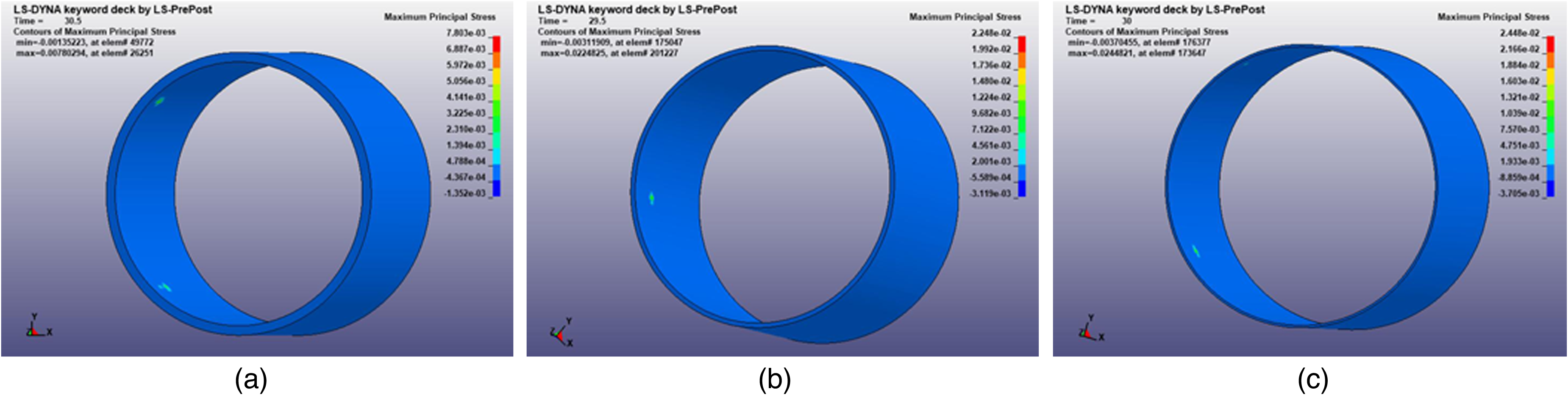
Simulation analysis results after optimization. (a) 2.00 mm thickness. (b) 1.00 mm thickness. (c) 0.50 mm thickness.
Stress values before and after optimization (MPa).

According to Table 7, the internal stresses in the x, y, and xy directions for the workpieces with different wall thicknesses were reduced. The principal-max direction indicates the direction of the maximum internal stress. After optimization, the maximum internal stresses in the principal-max direction for workpieces with a wall thickness of 2.00 mm, 1.00 mm, and 0.50 mm were reduced by 71.53%, 23.45%, and 31.65%, respectively, compared to before optimization. This indicates a significant reduction in internal stresses after optimization. The changes in internal stress changes are crucial for the manipulator. During the grasping process, the internal stress needs to be lower than the allowable internal stress of the workpiece to ensure that no damage occurs to the fragile workpiece.
Research on grasping law of manipulator
During the high-speed gripping of fragile workpieces, the contact impact stress between the fingers of the manipulator and the fragile workpiece can easily lead to damage to the fragile workpieces. By establishing a contact collision model for the manipulator gripping fragile workpieces and exploring the contact-collision laws, it is of great significance to reasonably determine the motion parameters of the manipulator when the manipulator grasps the fragile parts.
Discussion on impact stress for the manipulator grabbing the fragile parts
According to the structure and parameters of the designed manipulator's drive mechanism, the corresponding driving speed of the cylinder and the impact speed of the finger touching the workpiece can be obtained from Eq. (19) and Table 2. Seventeen kinds of speeds as shown in Table 8 are selected for simulation analysis when the manipulator grasps the fragile parts.
Driving speed and impact speed of the manipulator (mm/s).

Five types of fragile parts with different wall thicknesses were selected for impact stress simulation: 0.5 mm, 1 mm, 1.5 mm, 2 mm, and 2.5 mm. For ordinary glass, when the failure stress is approximately 70 MPa and the maximum effective plastic strain is 0.01, the simulation results align closely with the experimental results. 44 In this study, a stress threshold of 70 MPa is adopted.
Analyze the manipulator contact collision law, three-finger equivalent force conversion is necessary.
26
Under the assumption that the strain of the circle is uniform and that each unit is subjected to a force of F, the area is
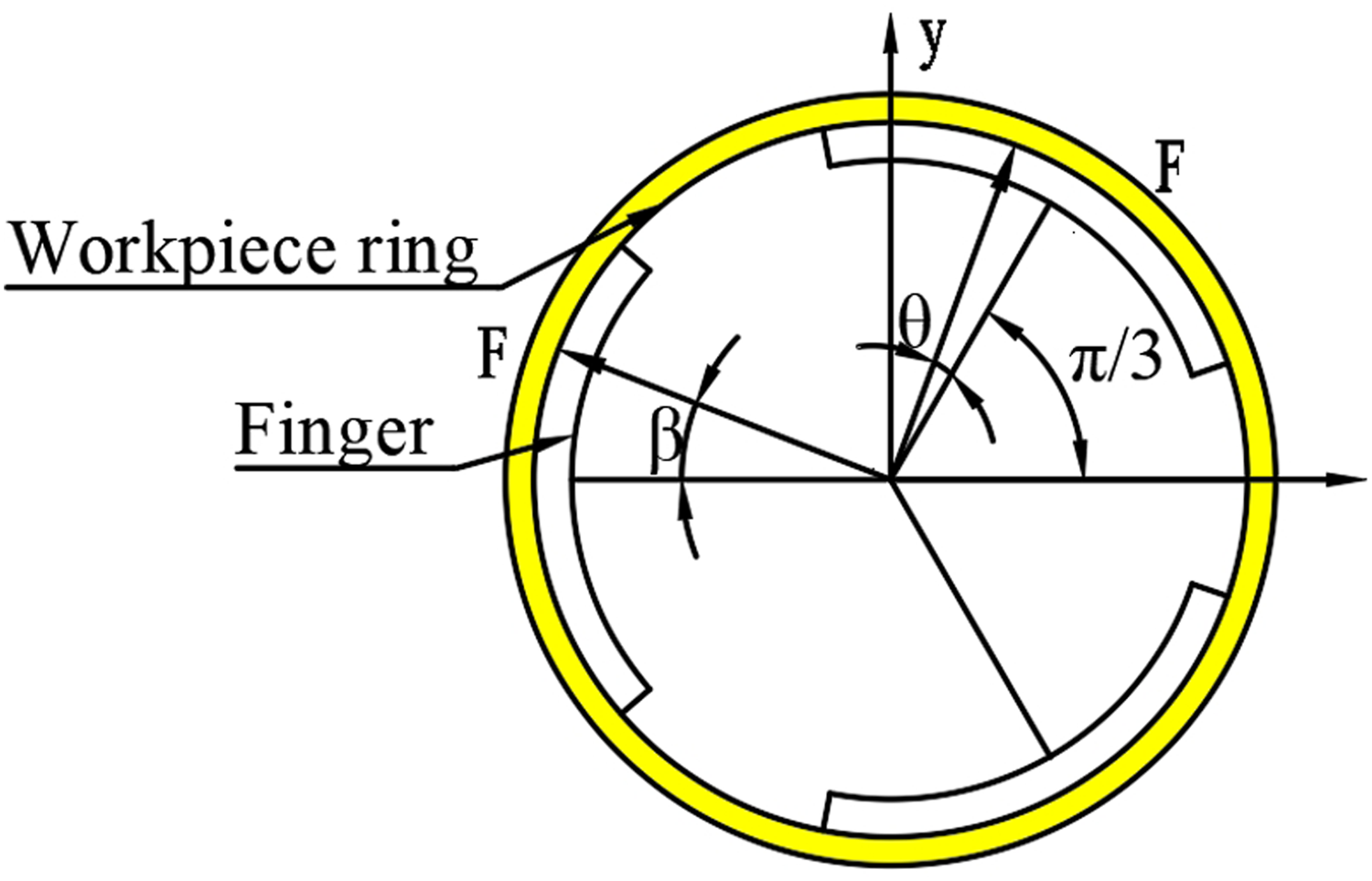
Layout and force of three claws of the manipulator.
When a workpiece is subjected to the action of a finger, the finger arrangement shown in the left part of Figure 16, 


The stress variation of the manipulator impacting the thin-wall fragile parts.
Stress of the workpiece at the manipulator's different driving speeds.

As shown in Figure 17, the stresses of the fragile parts increase with the increase of the manipulator's driver speed and decrease with the increase of the thickness of the fragile parts. It can be seen from Figure 17 that the different thickness of the fragile parts has a different influence on the contact impact stress when the manipulator grasps the fragile parts, while the contact impact stress of the thinner fragile parts is more sensitive to the change of the driving speed of the manipulator.
70 MPa is used as the threshold to define internal stress as the damage stress of the workpiece in our study. In Figure 17, for the fragile parts with a wall thickness of 0.5 mm, the contact impact stress changes rapidly as the driving speed of the manipulator increases up to 1750 mm/s, and changes slowly after the driving speed is greater than 1750 mm/s. When the driver speed of the manipulator exceeds 2750 mm/s, the contact impact stress of the fragile parts approaches 70 MPa. When the driver speed of the manipulator is 3000 mm/s, the impact stress of the fragile parts reaches 71.21 MPa, the workpiece will break.
For the fragile parts with a wall thickness of 1 mm, the impact stress changes greatly when the driving speed is less than 2500 mm/s, and the stress increases more rapidly when the driving speed is greater than 2500 mm/s. When the driving speed is 3750 mm/s, the impact stress on the fragile parts reaches 69.46 MPa, close to the critical value.
For the fragile parts with a wall thickness of 1.5 mm and 2 mm, the impact stresses on the fragile parts have the same change trend. As the driving speed of the manipulator increases, the impact stresses continue the upward trend. For the workpiece with a wall thickness of 1.5 mm and 2 mm, the impact stress on the workpiece is 72.48 MPa and 72.16 MPa, the corresponding driving speed is 3750 mm/s and 4250 mm/s, respectively.
For the fragile parts with a wall thickness of 2.5 mm, the stress change trend of the parts is slow, when the manipulator driving speed is less than 2000 mm/s. After the driving speed exceeds 2000 mm/s, the stress change of the workpiece shows a sharp upward trend as the driving speed increases. When the driving speed is 4750 mm/s, the impact stress on the fragile parts is 73.43 MPa.
It needs to take a long time to simulate the contact impact when the manipulator grabs the workpiece. To obtain the stress variation law in grasping more quickly, the Kriging interpolation method is used to predict the impact stress of the workpiece at different driving speeds.
The general law construction of contact stress for manipulator grasping based on the Kriging prediction model
To expedite the evaluation of grasping contact stress and optimize the operating parameters of the manipulator, a Kriging prediction model for contact stress is established. This approach is adopted due to the complexity involved in designing a finite element model for calculating the contact stress of the manipulator grasping a workpiece, as well as the lengthy simulation time required. By utilizing existing calculation results and performing similar parameter operations, the Kriging prediction model enables a quick assessment of grasping contact stress and facilitates the optimization of manipulator operating parameters.
The Kriging interpolation method is a spatial local interpolation technique that enables unbiased optimal estimation within a limited region. 45 The method utilizes experimental data as calculation points and applies weighted interpolation to obtain the value data thereby reflecting the spatial structural characteristics of the corresponding variables.
For a given m sample points 
For sample points 


Here, the estimation of the parameter 
The impact simulation experiment of the manipulator studied in this paper takes workpiece wall thickness and impact velocity as independent variables, in which the wall thickness interval is 0.5–2.5 mm and the velocity interval is 750–4750 mm/s. The impact stress sample points for the different speeds and wall thicknesses are written into the S sample set.
The principal-max stress is the output variable, while multiple stresses are written to the sample set Y. The regression model of the Kriging proxy model is expressed by a zero-order polynomial, while the correlation function adopts the Gaussian function. The kriging model is based on a certain number of sample points.
The accuracy of Kriging's prediction model is influenced by the selection of sample points. In this case, a rectangular grid design is employed, and the sample points for wall thickness and impact velocity are uniformly distributed. This approach effectively controls or reduces uncertainty in calculation and prediction, thereby enhancing the reliability of the prediction model.
To enhance the overall accuracy of the prediction model, the mean square error criterion is selected as the basis for judging the prediction interpolation error, improving the global accuracy. 46 After successfully constructing the initial proxy model, additional sample points were added to improve the interpolation accuracy of the prediction model as listed in Table 9. These new sample points were inserted within the uniform rectangular sample points, specifically at driving velocities of 1125 mm/s, 2125 mm/s, 3125 mm/s, and 4125 mm/s. These velocities fall within the range of 1000 mm/s to 1250 mm/s, 2000 mm/s to 2250 mm/s, 3000 mm/s to 3225 mm/s, and 4250 mm/s to 4500 mm/s, respectively. Additionally, the wall thicknesses of 0.75 mm and 1.75 mm were included as new sample points. Joint modeling and simulation analysis were conducted using SolidWorks, HyperMesh, and LS-DYNA software. The wall thickness, impact velocity, and simulation results of the stress were uniformly recorded in the sample set, as shown in Table 10. The addition of new sample points improves the fitting degree of the prediction model.
The stress on the workpiece.

Using the DACE toolbox of MATLAB software, the wall thickness and impact speed are set as X and Y coordinates and stress as Z coordinates, while function instructions in the toolbox are called through programming to calculate the prediction model of the stress in terms of different wall thickness and driving speed conditions, as shown in Figure 18.

The principal-max stress prediction plot.
As shown in Figure 18, when the wall thickness of the workpiece falls within 1.5 to 2.5 mm and the driving speed falls within 750 to 2250 mm/s, the stress change trend is relatively stable. With the increase of the driving speed and the decrease of the workpiece wall thickness, the contact impact stress exhibits a sharp upward trend. Based on the changing trend depicted in Figure 18, it can be observed that the fragile part experiences an instantaneous excessive stress concentration phenomenon when the wall thickness is less than 1 mm and the manipulator drive speed exceeds 2250 mm/s. This stress concentration has the potential to cause damage to the fragile part.
Determination and discussion of feasible range for grasping parameters under different wall thickness conditions
For ordinary glass, its failure stress varies between 50 and 90 MPa. When the failure stress is about 70 MPa, the maximum effective plastic strain is 0.01, while the simulation results are like the test results. 26 Through changing drive speed and fragile part thickness in the grasping process of the manipulator, and analyzing the result shown in Figure 18, the following conclusions are drawn:
Due to the poor tensile strength of fragile glass parts, they are more sensitive to tensile stress. From Figures 17 and 18, it can be observed that, under the same grasping conditions, changes in the wall thickness of fragile glass parts have a greater impact on impact stress compared to changes in impact speed. On the other hand, under the same wall thickness condition, variations in impact speed significantly impact grasping reliability. Changes in impact velocity directly affect the magnitude of the impact, resulting in stress concentration. The increase in instantaneous impact force during the collision process reduces the reliability of the grip.
Based on the analysis results from the specific example, when the workpiece wall thickness is 2 mm and the grasping drive speed exceeds 3500 mm/s, the stress on the fragile parts reaches approximately 72 MPa, leading to the breakage of the fragile parts. Similarly, when the wall thickness of the fragile part is 0.5 mm and the grasping drive speed exceeds 2500 mm/s, the stress on the fragile part increases sharply and approaches the fragile part's stress limit of 70 MPa, indicating that the fragile part is on the verge of failure. Further increase in speed could result in the immediate destruction of the fragile part. Additionally, when the drive speed exceeds 3000 mm/s, the stress on the fragile part exceeds 70Mpa, resulting in damage to the workpiece. Lastly, when the wall thickness is 0.25 mm and the driving speed is 1250 mm/s, the workpiece experiences failure, with the maximum stress at the point of failure reaching approximately 76 MPa.
From Figure 18, it can be observed that the thickness of the fragile workpiece varies between 2.5 mm and 0.25 mm. When the driving speed exceeds 3000 mm/s, the stress experienced by the workpiece increases sharply, ultimately failing. To prevent the destruction of the fragile workpiece, it is recommended to maintain the driving speed of the mechanical claw below 3000 mm/s and ensure that the thickness of the workpiece is greater than 0.5 mm.
To visualize the stress prediction, this study uses the GUI sub-module of MATLAB to investigate the stress prediction results and designs the GUI interface for the Kriging prediction model as shown in Figure 19. After running the program, the worker inputs parameters such as wall thickness and driving speed, and the GUI interface outputs the maximum internal stress to which the workpiece is subjected, to assess whether damage occurs to the workpiece gripped by the manipulator, and to provide a reference for subsequent work. The allowable stress value is set in the system, and when the predicted maximum stress value reaches or exceeds the allowable stress value, the system will give a prompt.

The principal-max stress GUI interface.
Experimental verification
To verify the accuracy of the finite element simulation results in Part 5, a stress test bench was established, as shown in Figure 20.

Stress test bench. 1. Manipulator 2. Precision regulator 3. Workpiece 4. Upper computer 5. Motion module 6. Solenoid valve 7. Exhaust throttle 8. DH3816 static strain gauge.
The actuation modules of the experimental equipment consist of the HIWIN corporation KE09010C-500AF0M and KE09010C-250AF0M single-axis linear motion ball screw drives, serving as the horizontal and vertical motion modules, respectively. The KE09010C-500AF0M module has an effective stroke of 500 mm with a ball screw lead of 10 mm. The KE09010C-250AF0M module has an effective stroke of 250 mm with a ball screw lead of 10 mm. The RIZE 60CM30X stepper motor by Leadshine Corporation is selected as the driving motor for both motion modules, and the motion control is achieved using the MC403 multi-axis motion control card by TRIO Motion Control Ltd, UK.
After the workpiece was positioned in the positioning block, the experimental equipment was activated. The manipulator moved to the gripping position under the action of the motion module. The gripping of the workpiece was achieved by controlling the manipulator claw through the pneumatic control circuit. At this point, the DH3816 static strain gauge measured and recorded the stress on the workpiece. The opening speed of the manipulator claw could be adjusted through the pneumatic circuit. By replacing different types of workpieces and fine-tuning the required parameters, the same type of experiment could be repeated.
The gripper section of the actuator, as shown in Figure 21, is a self-designed custom fixture that concordance with the structural components of the previous simulation model. The cylinder selected is the MHS3 series parallel three-jaw open-close cylinder manufactured by SMC Corporation, to validate the finite element simulation stress results in Section 5. The cylinder has a diameter of 25 mm, operates within a pressure range of 0.2–0.6 megapascals, offers a repeatability of ±0.01, and has an outer diameter grip of 42 mm and an inner diameter grip of 47 mm. The standard finger stroke is 6 mm, with a maximum load of 15N and a maximum speed of 300 mm/s.
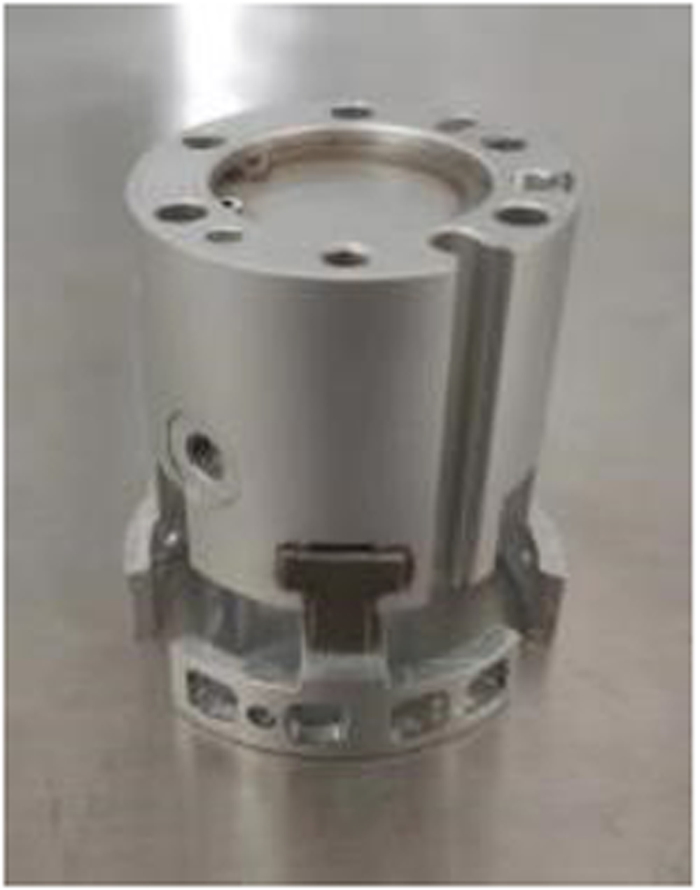
Manipulator module.
The DH3816 static strain testing system (Figure 20 (8)) consists of six channels, each equipped with 10 measurement points. The sampling rate can reach up to 60 points per second, with a maximum resolution of 1
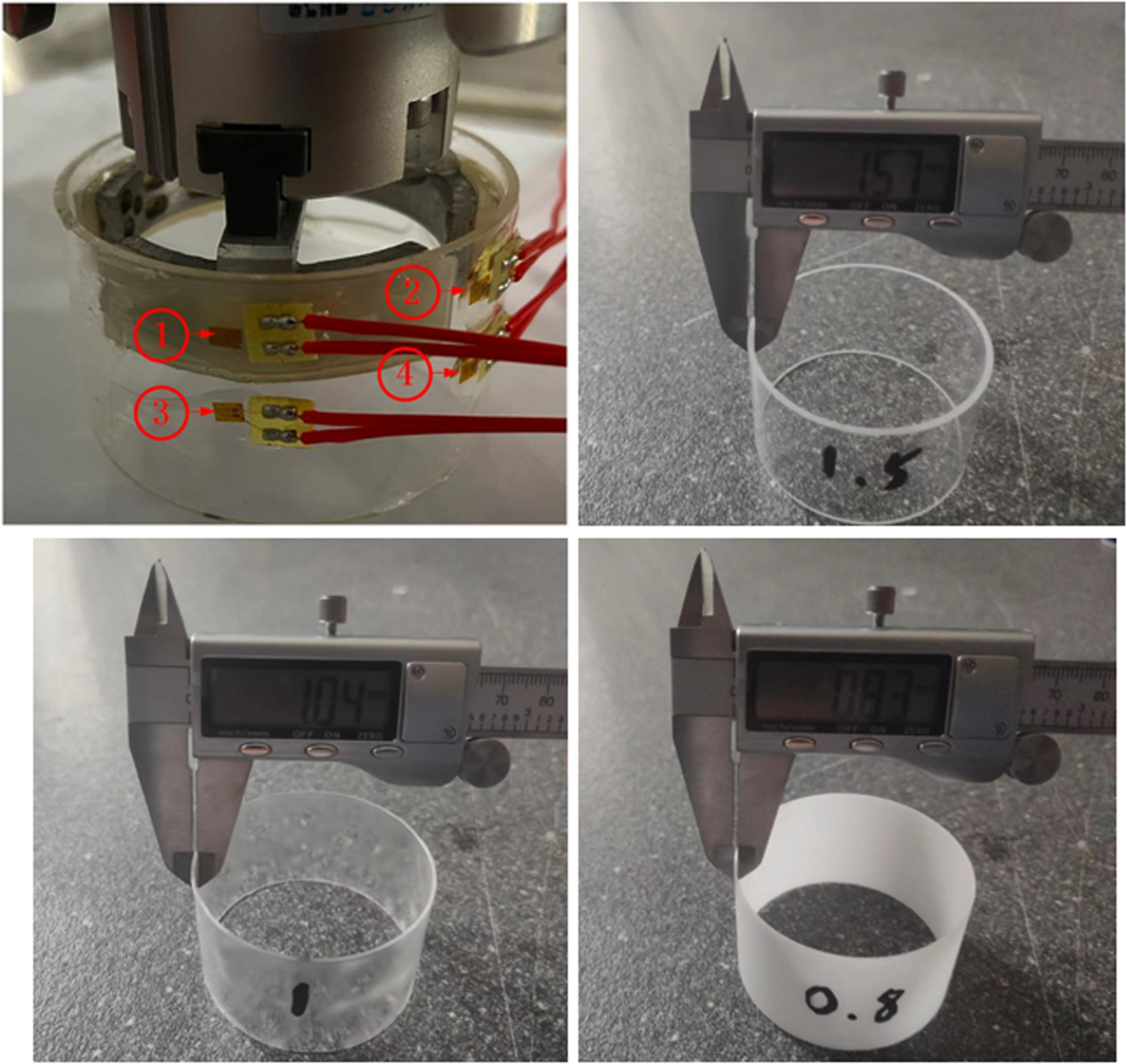
Thin wall glass ring and strain gauge pasting.
The finger body of the manipulator is made of aluminum alloy, and the thickness of the finger pad is 4 mm. The workpiece material is quartz glass. The relevant parameters are shown in Table 4 to Table 6. For the experiment, fragile rings with a height of 35.00 mm, an inner diameter of 27.75 mm, and different wall thicknesses (1.5 mm, 1 mm, 0.8 mm) were selected for grasping experiments. Figure 22 illustrates the actual sample of the workpiece, including the thickness, gripping position, and the location of the strain gauge used for testing. To improve the accuracy of stress measurement when the workpiece is grasped by the manipulator, four locations are selected to paste the strain gauge according to the stress cloud map in the simulation, and the strain gauge is connected by a quarter bridge.
To verify the validity of the simulation model presented in Section “Discussion on impact stress for the manipulator grabbing the fragile parts,” a series of experiments were conducted at three different speeds: 160 mm/s, 130 mm/s, and 100 mm/s. During the experiment, as shown in Figure 23, when the manipulator moved to grasp the thin-walled ring, the stress of each strain gauge on the surface of the thin-walled ring was measured and recorded by the continuous collection function of the static strain gauge in the continuous data collection mode. Each group of experiments was collected several times, and the average value of the maximum contact stress measured by the four strain gauges was taken as the experimental results of this group, as shown in Table 11.

DH3816 static stress–strain acquisition software interface and related settings.
Simulation and experimental data.

Due to the workpiece being constrained by the boundary conditions in the simulation of manipulator contact collision, the ideal single-finger contact effect can be achieved. In the experiment, a single manipulator could not reliably grasp fragile parts. To facilitate data comparison, the same experimental parameters were simulated according to the simulation model of manipulator contact collision, and the simulation results were multiplied by 5.7 according to formula (45), and the three-finger grasping stress transformation. The simulation data and the maximum stress measured by the experiment are shown in Table 11, and the comparison between the simulation and experiment is shown in Figure 24.

Comparison of experimental data and simulation data.
As the parameters of the experimental system and the manufacturing accuracy of the manipulator have certain deviations, as shown in Figure 24, there are certain differences between the experimental test results and the simulation results, but the overall difference is small, and the change law of the experimental data is consistent with that of the simulation data.
By comparing the contact impact stress results from the experiment and simulation, the relationship between workpiece stress wall thickness and contact impact velocity can be obtained. Analyzing Figure 24, it is evident that the workpiece stress decreases with the increase of the workpiece wall thickness. Additionally, the contact stress of the workpiece with different wall thicknesses is significantly influenced by the contact impact speed. The contact stress on the fragile workpiece grasped by the manipulator increases with the increase of the contact impact speed, and the experimental results are in good contrast with the simulation results.
Conclusion
The manufacturing process of diamond raw material, specifically pyrophyllite blocks, presents certain challenges in terms of installation conditions and working space. To address these limitations, the transferring and assembling of the workpiece must adopt an internal support-grabbing mode. In response, an internal bracing grasping manipulator system has been designed specifically for grasping fragile thin-wall workpieces. By establishing an optimization model for the manipulator transmission mechanism, the structure parameters of the manipulator are optimized while maintaining an overall average speed of the mechanical finger. The main objective of the optimization is to minimize the impact velocity when the mechanical finger encounters the workpiece. The dimension parameter of the connecting rod is treated as a variable, and GA is utilized. The optimization results demonstrate that after optimization, the contact impact speed of the manipulator when grasping fragile parts is reduced by 44.80%. A joint modeling approach combining SolidWorks, HyperMesh, and LS-DYNA, was to analyze the impact of the mechanical finger on the fragile part. A finite element model was established to simulate and analyze the collision process between the mechanical finger and the fragile part. During the manipulator operation, the correlation between the impact velocity of the mechanical finger, the wall thickness of the workpiece, and the internal stress of the workpiece was investigated. By establishing the Kriging proxy model, it is very easy to predict the contact stress under different wall thickness and grasping speed conditions. The research process established the basis for improving the finger structure and determining the working process parameters. The rationality of relevant simulation results is also verified by experiments.
Footnotes
Declaration of conflicting interests
The authors declared no potential conflicts of interest with respect to the research, authorship, and/or publication of this article.
Funding
The authors disclosed receipt of the following financial support for the research, authorship, and/or publication of this article: This project was supported by the National Natural Science Foundation of China (Grant Nos. 52075500, 52304301), the Key Science and Technology Research Project of the Henan Province (Grant Nos. 232102221033, 242102221057), Program for Science and Technology Innovation Talents in Universities of Henan Province (Grant No. 22HASTIT023).
Data availability statement
Data sharing not applicable to this article as no datasets were generated or analyzed during the current study.