
Abstract
This paper explores the design and control of a center-rotor type pentacopter that can move in contact with a wall to accurately measure cracks in a concrete outer wall. A center rotor pentacopter is a type of pentacopter that uses an electric ducted fan (EDF) motor and two axis servomotors at the center of gravity of the quadcopter. Center-rotor pentacopters are characterized by the ability to generate thrust in the desired direction using two servomotors and an EDF motor to maintain a stable attitude without tilting or leaning during flight. In this paper, the mathematical modeling of a center-rotor pentacopter was verified through simulation and compared with a regular quadcopter. We also simulated the thrust of the center rotor to see how much it could withstand when a sudden gust of wind occurred. Then, we built a pentacopter and measured the cracks and calculated the width of the cracks through the actual pentacopter in addition to flight experiments. The results showed the advantages and applicability of the pentacopter.
Introduction
Recently, the number of facilities subject to maintenance has been increasing due to the aging of facilities. The number of class 1–2 facilities under the Special Act on Safety Management of Domestic Facilities is estimated to be 87,124 as of 2017. In addition, the aging rate is expected to increase to more than 40% in the next 20 years. 1 In the United States, Japan, and other countries, the aging of bridge facilities has been in full swing since the 2010s, and measures are being taken to address it. The allowable crack width in each country is mostly 0.4 mm or less, which requires early detection of cracks. 2 The classical way to measure this is by performing a visual inspection by a human operator using a specialized vehicle. However, this can lead to human casualties such as worker falls, and it can also require road closures for inspections. Therefore, in recent years, researchers have been actively working on replacing this by using drones. The images taken by drones are used to measure cracks of concrete outer wall in various ways, including image processing and artificial intelligence.3–8 In the work of Kim et al., used drones to inspect the outside of a dam was able to measure cracks larger than 0.9 mm while staying about 8 m away from the wall. 3 and Kim et al. to measure cracks smaller than 0.5 mm, a drone was flown as close as possible to an outer wall to take pictures, and the images were then processed to estimate the width of cracks smaller than 0.25 mm. 4 Another study used deep learning techniques to detect cracks in concrete and measure their width.5,6 To measure cracks and ensure the reliability of the measurements, the resolution of the camera and the shooting distance are fundamentally important. Therefore, to measure cracks in concrete outer walls of bridges, dams, apartments, etc. with a drone, the drone must be able to maintain a stable distance from the wall and move smoothly. Furthermore, during noncontact flight, sudden exposure to gusts of wind can lead to unexpected displacement or attitude oscillations, significantly compromising flight stability and posing challenges in flight control. Gusts in GPS-shadowed areas such as the underside of a bridge can cause the drone to lose not only the location of the crack, but also its flight position. One of the simplest ways to maintain a stable distance from the wall and withstand sudden gusts of wind is to contact the wall. Most drones used for wall crack detection and measurement use common drone-shaped airframes, such as DJI's Phantom. However, these airframes have the disadvantage that the impact on the drone during a collision is not negligible, as shown by Kim et al., which analyzed the collision of a drone and a wall, and it is difficult to move the airframe after contact. 9 Therefore, wall-climbing robots have been widely studied to solve these problems.10–13 One example is a wall-climbing drone. In the work of Myeong et al., wall-climbing drones are designed to contact to a wall by tilting the aircraft 90° instantaneously. According to the paper, the success rate of contacting to the wall is high, but there is a possibility of failure, and further research on stability is needed.10,11 In addition, the recently developed wall-climbing quadruped robot (MARVEL) uses electromagnets to climb walls, which has the disadvantage that it can only climb structures made of steel and is not applicable to walls made of concrete. 12 Also, drones that have studied contact to mitigate collisions with walls have the problem of not being able to move after contact. 13 To solve these problems, this study proposes a central rotor pentacopter drone with a horizontal flight capability that can be vertically contacted to an outer wall while minimizing the attitude change of the drone and can move smoothly over the wall surface even after contacting the wall.
Configuration of the central-rotor type pentacopter system
Hardware design of the central-rotor type pentacopter
The central-rotor type pentacopter consists of three main parts: Quad Rotor Part (QRP), Central Rotor Part (CRP), and Wall Contact Part (WCP), as shown in Figure 1. The QRP is the main driving part for controlling the posture and altitude of the aircraft and has the same quadcopter structure traditionally used. CRP is composed of electric ducted-fan (EDF) motor for generating thrust, as shown in Figure 2, and two servo motors for controlling roll and pitch angles. Figure 3(left) shows the direction of thrust when the pitch angle of the central rotor is 90°, and the aircraft moves horizontally forward at this time. Figure 3(right) shows the situation when the roll angle is 90°, and the aircraft moves horizontally in the y-axis direction. WCP is located on the front of the aircraft and helps to absorb the impact of the aircraft when contacted to the wall, as well as ensuring smooth movement in both horizontal and vertical directions after contact. The omni wheel used for this purpose is a specialized wheel design where auxiliary wheels (small rollers), as seen in the omni wheel part of Figure 4, are arranged around the main wheel at right angles, allowing the main wheel to move forward and backward while the auxiliary wheels can rotate independently from side to side. This configuration, consisting of Inner and Outer roller pairs, enables the wheel to move in all directions, hence referred to as an omnidirectional wheel, and it has already been applied to omnidirectional wheeled mobile robots.
14
Therefore, considering these advantages, the omni-wheels were placed at four locations of the WCP as shown in Figure 4, and springs were applied to both ends of the wheel's axis to mitigate airframe shock and reduce vibration due to the step between the inner roller and outer roller. Figure 5 shows the case where the front of the WCP is contacted to the wall. In the left figure, the central rotor thrust

Central-rotor type pentacopter configuration diagram.

Central-rotor drive configuration diagram.

Direction of thrust according to the angle of the central rotor.

Configuration for wall contact part.

Wall contact and movement of the aircraft according to the direction of the central rotor thrust.
Modeling of central-rotor type pentacopter
Figure 6 defines the coordinates for modeling a pentacopter. The angular velocity of rotor

Coordinate systems of the pentacopter.
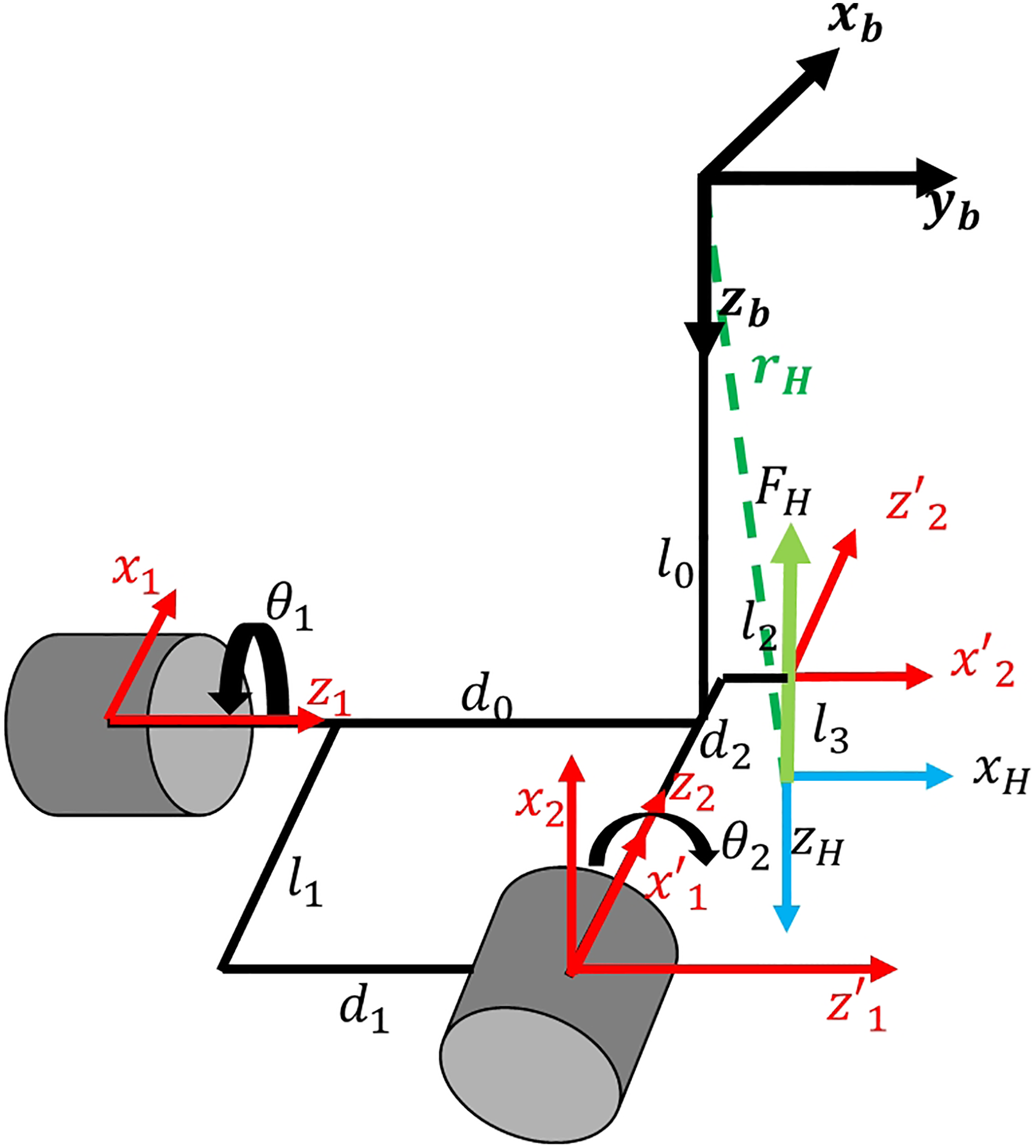
Diagram between body frame and H frame.
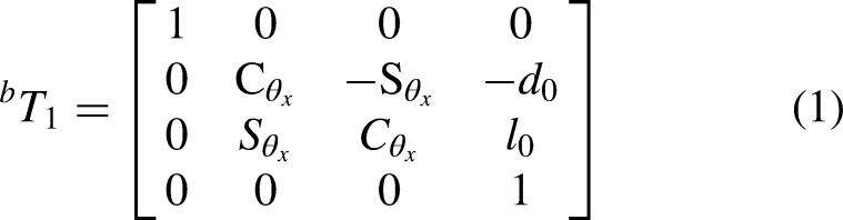
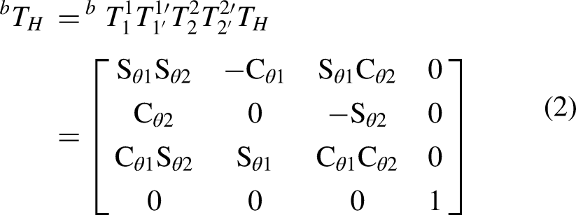
To obtain the forward kinematics for converting the force


D-H parameters for the pentacopter.

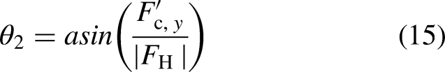
Next, to generate force in the desired direction from the central rotor, we need to determine the roll (


Relation between central rotor force and desired force.
Thus,


Thrust graph of 6S EDF motor.
Dynamic modeling of central-rotor type pentacopter
The dynamic modeling of a center-rotor pentacopter can basically be interpreted based on the modeling of a quadcopter. The absolute position of the pentacopter in the inertial coordinate system is represented by 


Diagram of a pentacopter contacting an outer wall.
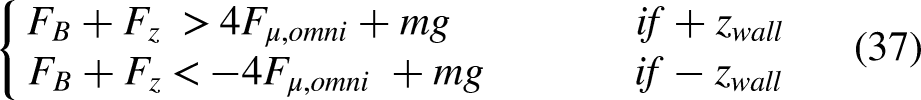
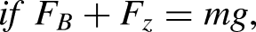
The thrust generated by the center rotor can be represented by equations (32)–(34).


Next, the maximum static frictional force (

Design of control system for central-rotor type pentacopter
Configuration of control system for central-rotor type pentacopter
The control system of a central-rotor type pentacopter is configured as shown in Figure 11. Using the Pixhawk4 Flight Controller (FC), the control system drives the ducted fan motor and two servo motors of the central rotor, as well as the four BLDC motors of the main rotors, based on external control inputs. Additionally, for aircraft control, the system utilizes a Lite-Lidar v3 (ToF Lidar—Time of Flight Lidar) sensor and PX4 Flow (Optical Flow) for altitude estimation and speed estimation.

Control system diagram.
Control of central-rotor type pentacopter
As a method for controlling drones, PID control is the most widely used control algorithm. PID control is used for altitude and attitude control of drones, and it is applied to pentacopter.22–25 Figure 12 depicts the control configuration of the central-rotor type pentacopter. It consists of Quad Rotor Control (QRC) for controlling the four propellers of the QRP and Central Rotor Control (CRC) for controlling the central rotor of the CRP, controlled independently. The QRC section depicted in Figure 12 utilizes PID control to regulate the aircraft's attitude and altitude. Equations (39)–(46) represent the P-PID controllers applied to the pentacopter.


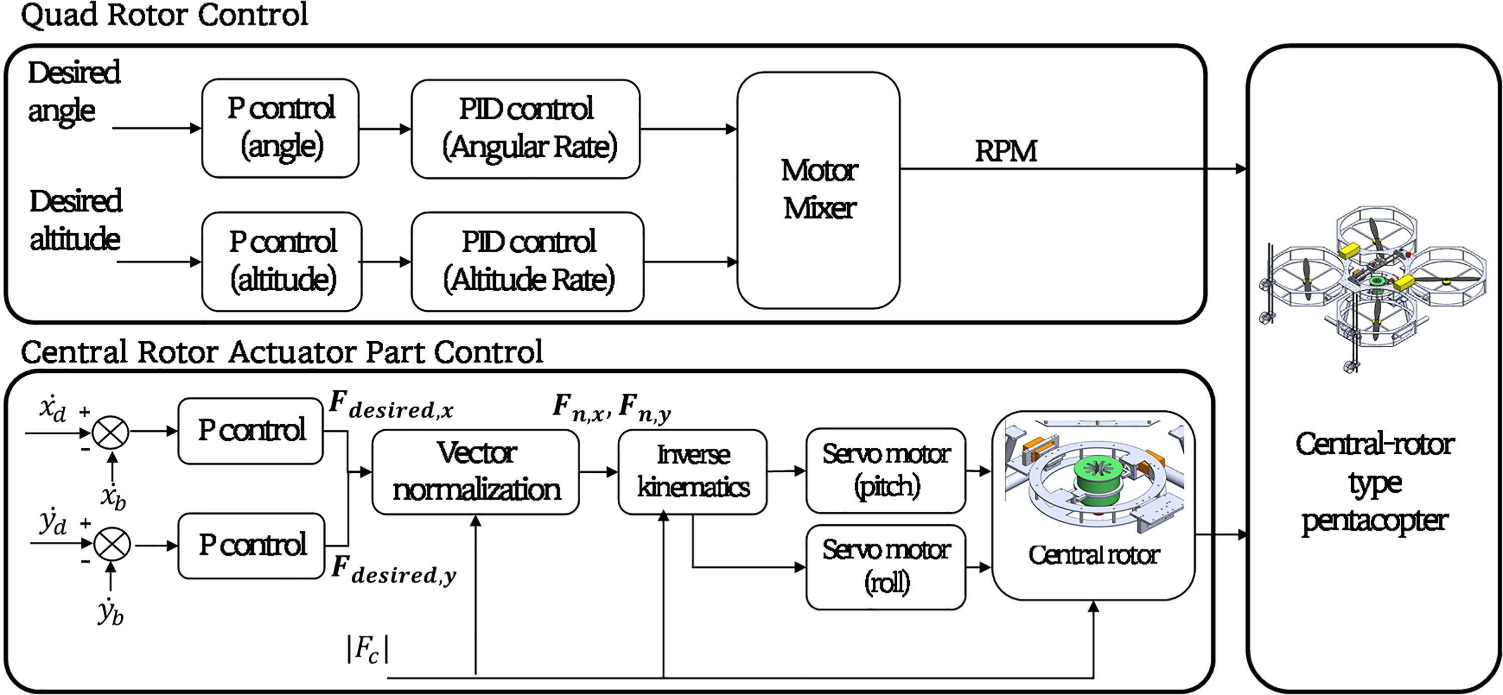
Control configuration of the central-rotor type pentacopter.
The CRC section illustrated in Figure 12 enables the pentacopter to maintain its speed or hover by comparing the target speed (
In addition, for the convenience of control, the value of 

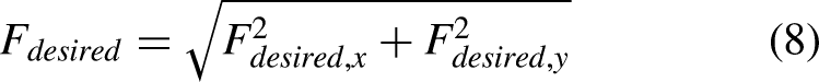
Therefore, equations (49) and (50) normalizes the vector to obtain 

Simulations
Based on the modeling of the pentacopter obtained earlier, simulations are conducted. The parameters used for the simulations are shown in Table 2. To verify the horizontal motion of the pentacopter controlled by the central rotor of the pentacopter, the target roll (
Parameters for simulations.

Additionally, after setting the central rotor's thrust at 3 N, a step input of 1 m/s in the x-direction was applied after 5 s. The simulation results are shown in Figure 13 (center). It takes about 2 s to reach the target altitude of 2 m after takeoff, during which time the pentacopter maintains an attitude of 0°. The maximum change in the pitch angle of about −0.2° during initial takeoff is due to the weight center being slightly biased in the 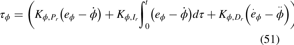


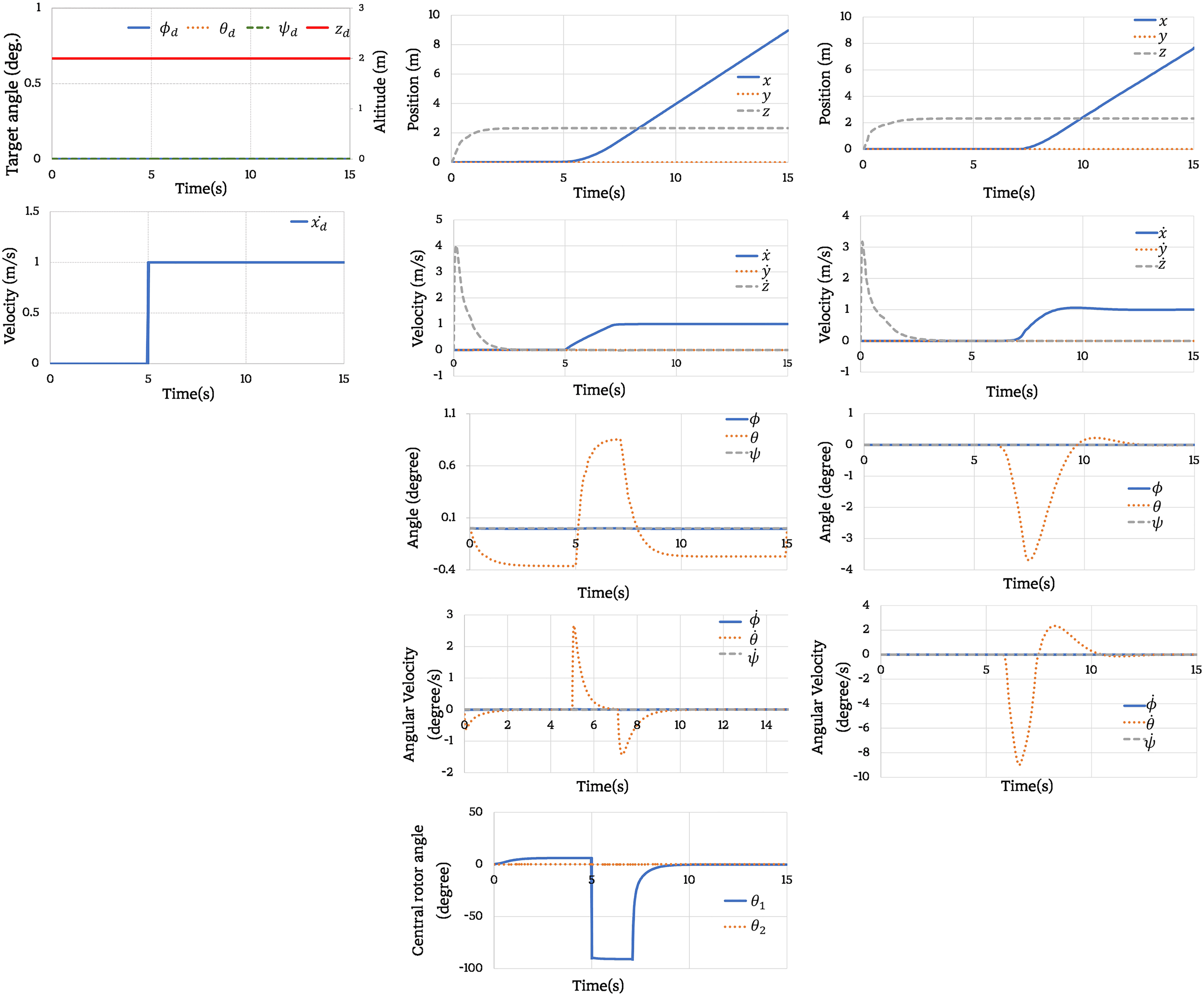
Simulation results of controlling a center-rotor pentacopter (center) and a quadcopter (right) for a target input (left).
When the same target input as in Figure 13 (left) is given, it can be observed that the pentacopter tilts up to a maximum of approximately 4.58° in pitch while moving forward. By comparing the case with and without using a central rotor, it can be concluded that when using a central rotor, the attitude changes during flight are significantly reduced. The following is a simulation of whether the pentacopter can maintain its position under the force of the center rotor without changing its attitude when subjected to a sudden gust of wind. The parameters of the pentacopter are the same as in Table 2, with a standard air density
Therefore, in this study, the wind speed for sudden gusts is assumed to be 6 m/s for simulation (i.e.,
Figure 14 is the wind input, generate a north wind between 5 and 9 s and an east wind between 7 and 11 s. The results of the pentacopter's response to the wind are shown in Figure 15. In the case of (a), it can be seen that the pentacopter is moved by the gust because no speed control using the central rotor or attitude control was applied to the changes in

Wind input.

Simulation result for gust. (a) Simulation results without using the central rotor and attitude-based speed control. (b) Simulation results using attitude-based speed control without using the central rotor. (c) Simulation results using only the central rotor without using attitude-based speed control.
Experimental results
Table 3 and Figure 16 show the specifications and appearance of the designed and manufactured center-rotor pentacopter. The weight is about 5.2 kg, the dimensions of the airframe are 940 × 1020 × 325 mm, and the flight time is about 10 min. The following are the experimental results conducted by inputting a 1 m/s command in the x-axis direction to evaluate the horizontal movement performance. Figure 17 shows that the target input is reached within about 5 s after entering the command in the

Completed prototype of the central rotor type pentacopter.

Velocity control results for horizontal movement in the
Specifications of the central rotor type pentacopter.
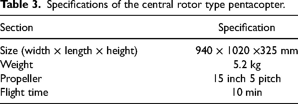
Figure 18 shows the variation of the roll angle and pitch angle when flying as in Figure 17. According to Table 4, we can see that the roll angle remains at a mean of −0.47298° with a deviation of 0.000509 and the pitch angle at a mean of −0.3445° with a deviation of 0.000179 when traveling horizontally. Figure 19 shows the experimental results of on continuous vertical movement in the − and + directions in the y-axis direction. Figure 20 represents the changing roll and pitch angles during continuous movement.
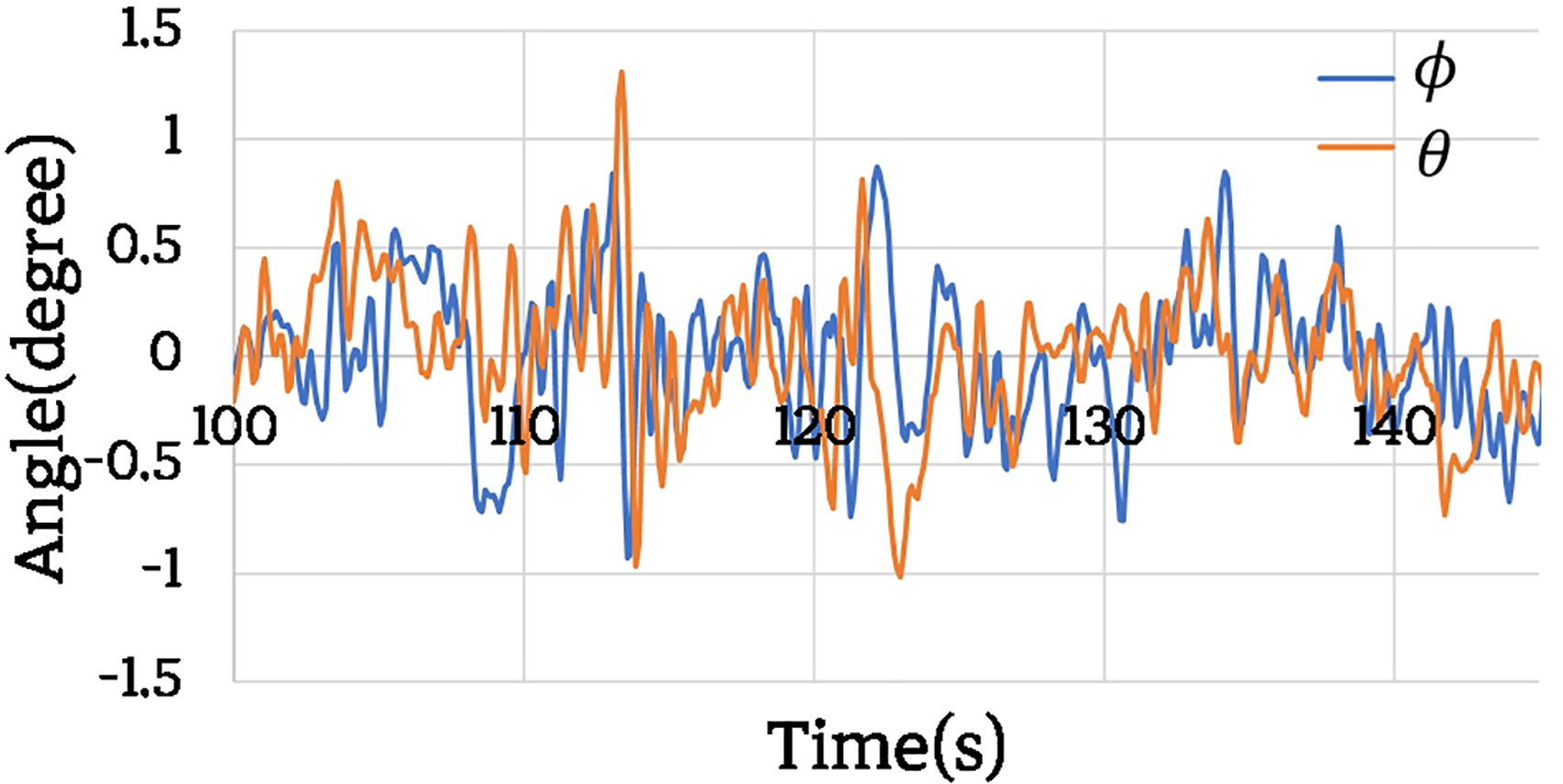
Roll and pitch angles of a center-rotor pentacopter during horizontal movement in the

Velocity control results for horizontal movement in the
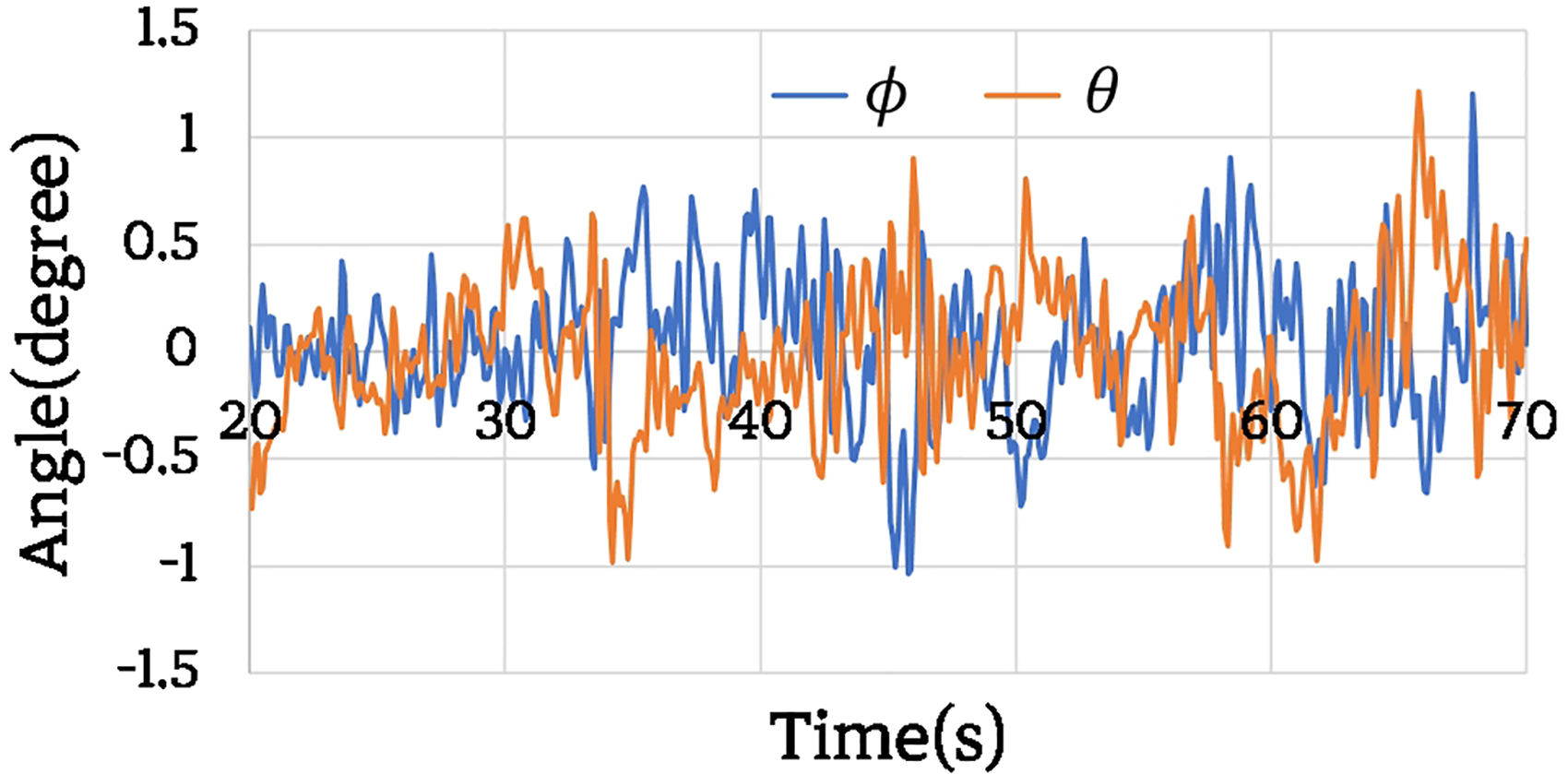
Roll and pitch angles of a center-rotor pentacopter during horizontal movement in the
Average and variance of roll and pitch angle during horizontal directional movement.

As shown in Table 5, the angles of roll and pitch maintain an average of −0.00124° and 0.026977°, respectively, during movement, and the variances are 0.1378 and 0.093012, respectively. One of the purposes of the central rotor-type pentacopter is to be stably contacted to a wall through horizontal flight. Therefore, experiments are conducted to verify whether the pentacopter can be contacted to the wall. In addition, it is necessary to measure the force exerted when the pentacopter is contacted to the wall.
Average and variance of roll and pitch angle during vertical directional movement.

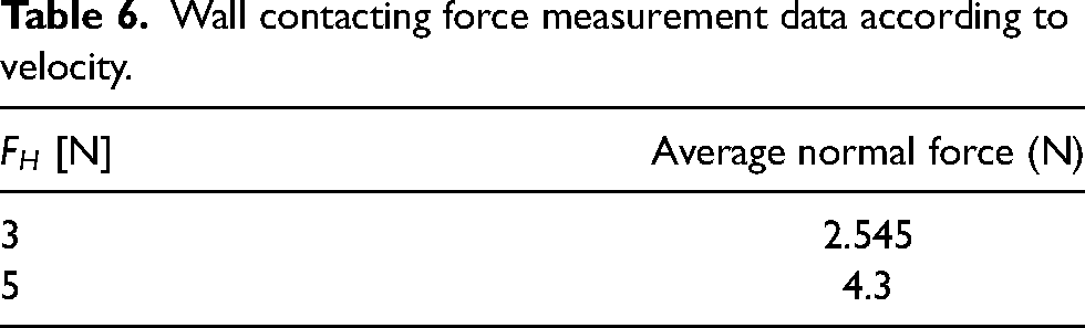
Figure 21 shows a wall contact device that can measure the contacting force when the pentacopter is contacted to the wall. The wall contact device is constructed using a load cell that can measure up to 5 kg. Figure 22 is a snapshot of the process of the pentacopter being contacted to the wall, and Figure 23 shows the results of measuring the normal force between the wall and the contact device. To measure the force of contact with the wall, we conducted an experiment to measure the normal force when the pentacopter was placed in contact with a wall using the center rotor, and the thrust of the center rotor was generated at 3 N and 5 N in the forward direction of the pentacopter

Normal force measurement device using loadcell sensor.

Snapshots of the wall contact process.

Normal force measurement data graph (up:
Sections (a)–(c) represent the pentacopter traveling until it is contacted to the wall, with a measurement of 0 g. Sections (d)–(e) represent the collision with the wall, with the normal force increasing to approximately 1200

Snapshots of the horizontal flight process after wall contact.
Wall contacting force measurement data according to velocity.
Additionally, to evaluate the effectiveness of the contact to the wall, a distance sensor is contacted to the front of the pentacopter to measure the distance between the pentacopter and the wall. The experimental procedure is as follows: First, the pentacopter elevates its altitude using the four main rotors and then contacts itself to the starting point labeled as (1) using the central rotor. Subsequently, in section (1) to (3), the pentacopter performs a rightward horizontal movement using the central rotor, while in section (3) to (4), the pentacopter lowers its altitude using the main rotors. Finally, sections (4) to (6) represent the process of the pentacopter moving horizontally to the left using the central rotor. The experimental results are presented in Table 7. During the total 6 m flight, the roll and pitch angles showed minimal variation, measuring 0.007° and 0.015° respectively, indicating stable orientation. The distance from the wall was measured at 0.064 m, confirming successful contact. Furthermore, the pentacopter exhibited a y-axis velocity of 0.131 m/s during the movement in sections (1) to (3), while the velocity during the movement in sections (4) to (6) was 0.121 m/s.
Horizontal movement experimental results after wall contact.

Ensure that the pentacopter can measure the cracks smoothly and can measure the width of the cracks well. Figure 25 (left) shows the pentacopter shooting with the camera at point A, where the actual measurements were performed. Figure 25 (right) shows the actual measurements of 16 cracks. The camera used in the pentacopter was a Samsung Galaxy A52 s phone camera with a 64MP resolution and a field of view of 0.705 m (W). The phone mounted on the pentacopter was positioned 0.3 m away from the outer wall. Figure 26 shows some images of the actual measured crack width (left) and the crack width measured by counting the number of pixels in the crack image (right). Table 8 shows the measured and calculated values for cracks 1–16. The error between the actual measured and calculated values is 0.079 mm on average, with a maximum error of 0.12 mm, which shows that the error is very small with simple image processing. In the same manner as Figure 26, Figure 27 shows the measurement of crack widths on a bridge with instantaneous wind speeds of up to 4.1 m/s. The crack widths could be measured as small as 0.0917 mm. Through this, it is understood that the measurement of crack widths in various concrete exterior walls is possible, and stable imaging is achievable even in gusty conditions.

Experiment on measuring cracks in bridges.

Actual measurement of cracks (left) and calculated values (right).
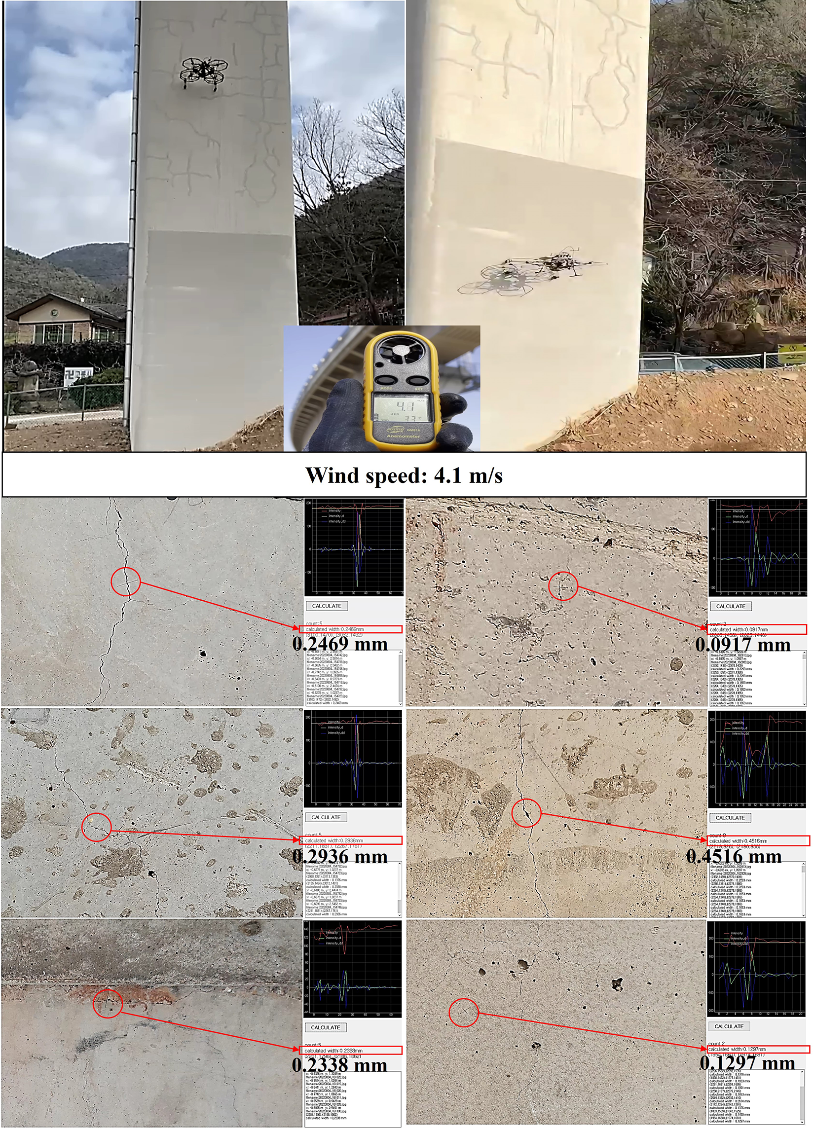
Crack measurement results for different concrete exterior walls.
Compare actual measured and calculated values for crack numbers.

AM: actual measurement; E: error.
Conclusions
The purpose of this study is to propose a mechanism and control method for a center-rotor type pentacopter as a method for detecting cracks in the outer walls of concrete structures such as dams and bridges and to accurately measure the width of the cracks. The proposed pentacopter can fly in a stable attitude without tilting or leaning by adding an EDF motor to the center of gravity of the aircraft to generate thrust. This allows it to make stable contact with external walls and perform vertical and horizontal maneuvers without changing its attitude after contact. To verify this, this paper (1) established a mathematical model of a central-rotor type pentacopter and conducted simulations to verify the differences from general drones, and confirmed through experiments that there is almost no attitude change when the pentacopter flies horizontally. (2) Simulated the ability of the pentacopter to cope with sudden gusts of wind and found that there is little attitude change in a 6 m/s gust and no significant change in speed. (3) Analyzed and experimentally verified the normal forces that occur when a center-rotor pentacopter contacts an outer wall. (4) Conducted experiments to test whether the center-rotor pentacopter can stably contact the outer wall and move after contact. (5) To verify the efficiency of the pentacopter, we measured the actual cracks on a bridge in a GPS-unavailable area and compared them with the cracks photographed using the pentacopter and found that the width of the cracks can be accurately measured with simple image processing. Therefore, we believe that the center rotor type pentacopter proposed in this paper can be used to detect cracks in concrete and accurately measure the width of cracks. In addition, we believe that it is possible to inspect in areas without GPS coverage.
However, the pentacopter studied in this paper was researched on concrete structures without curves. Therefore, the currently applied WCP form has difficulty adapting to curved walls, and additional research on WCP is needed. Additionally, since the pentacopter is piloted by a human, the pilot's flying skills are important, and since the photographed cracks are simply counted as the number of pixels, it is necessary to consider how to measure the width of the crack from where to start.
Therefore, if the positioning technology using UWB is further supplemented by combining technologies such as image processing and deep learning, it is expected to overcome the problems of infrastructure inspection and be widely applied to delivery services in high-rise buildings and apartments in the future.
Footnotes
Declaration of conflicting interests
The authors declared no potential conflicts of interest with respect to the research, authorship, and/or publication of this article.
Funding
The authors disclosed receipt of the following financial support for the research, authorship, and/or publication of this article: This research was supported by Korea Institute for Advancement of Technology (KIAT) grant funded by the Korea Government (MOTIE) (P0008473, HRD Program for Industrial Innovation) also was the result of the “Regional Specialized Industry Promotion Project + (R&D)” (S3262070) conducted by the Ministry of SMEs.