
Abstract
In this article, the dynamics of a seven degrees of freedom robot with a telescopic forearm for the spray-painting of large workpiece is investigated. A novel two-step inverse kinematic solving method that combines numerical and analytical approaches is proposed to solve the inverse kinematics of the seven degrees of freedom robot with two redundant degrees of freedom for spray-painting applications. Based on the kinematic model, the dynamic model is derived using the Newton–Euler method. For the dynamic parameter identification, the dynamic model is written in a linear form with respect to dynamic parameters. Considering the effect of the telescopic forearm on the dynamics of the robot, two novel performance indices concerning the inertial load and gravitational load in the joint space are proposed to evaluate the effect of the telescopic forearm on the dynamic load of the robot. Monte Carlo method is used to solve these two indices. This work is essential for the motion planning and control of the seven degrees of freedom spray-painting robot with a telescopic forearm.
Introduction
The spraying process is an important manufacturing procedure for the coating of some large workpieces. Due to the huge size of the workpiece, the semiautomatic spraying method is generally used. It is obvious that there are many disadvantages such as bad spraying environment, poor spraying quality, and low spraying efficiency. The most ideal solution is to use robots for automatic spraying. In general, it is required that the spray-painting robot has two rotational degrees of freedom (DOFs) and three translational DOFs to complete the painting of a workpiece with a conical surface. However, in practical applications, the workspace of a 5-DOF robot is not enough for the painting task of large workpieces and the 7-DOF redundant robot is generally used. 1 –3 The redundant DOF can not only enlarge the workspace but also be used to minimize energy dissipation, avoid joint limits, and so on. 4 –6
The inverse kinematics is an important issue in robotics, which is the basis of robot design and control. The inverse kinematics is to find the joint parameters by giving a specified position and orientation of the end effector. 7 –11 Some methods are proposed to find the inverse solution of kinematics for the robots with six or less DOFs and the exact solution with low computational cost can be found. 12,13 However, the 7-DOF redundant robots have complex inverse kinematics. 7 –11 For the 7-DOF robot, the system of equations is indeterminate and the inverse kinematics has many solutions. 14 –16 Some researchers have concluded that the inverse kinematics of a 7-DOF robot like the Barrett whole arm manipulator does not have analytical solutions. 17 Weghe et al. 18 reported that there is no closed-form solution of the inverse kinematics for manipulators with more than six links. Berenson et al. 19 state that the inverse kinematics of the 7-DOF whole arm manipulator cannot be found by utilizing the existing methods.
Dynamics plays an important role for the industrial application of robots, especially large robots. An accurate dynamic model is critical for the dynamic model-based control, which is the most popular control method for industrial robots. 20,21 In general, the accurate dynamic model is obtained through two steps: (1) The dynamic model is derived by using some modeling methods such as virtual work principle, Newton–Euler method, and Kane method. (2) The accurate dynamic parameters are identified by using the identification technology based on the linear form of dynamic model. Since the 7-DOF robot is redundant, its dynamics generally involve optimization problems. Thus, the dynamics of a 7-DOF robot is complex even if its structure looks simple. There are works that contribute to the dynamics of 7-DOF robot. He et al. 22 derived the dynamic model of a 7-DOF robot by using Newton–Euler method that requires the calculation of all of the internal reactions of constraint of the robot. Carbone et al. 23 obtained the dynamic model of a 7-DOF biped walking leg for a humanoid robot by using Newton–Euler formulation. Li et al. 24 derived the dynamics of the 7-DOF modular robot based on an improved Kane model theory that the sum of generalized force and generalized inertia force is zero. These works concentrate on the robot with constant-length links. For the robot with telescopic link in our research, it is important to investigate the effect of the length of telescopic link on the dynamics. In addition, for the dynamic parameter identification, the linear form of the dynamic model is required. 25,26 However, due to the complex and coupled dynamics of the 7-DOF robot, it is a difficult task to find the linear dynamic model with respect to the base dynamic parameters.
In this article, the dynamics of a novel 7-DOF spray-painting robot with a telescopic forearm is thoroughly investigated. The solution of the inverse kinematics is found by proposing a two-step inverse kinematic method that combines numerical and analytical approaches. The linear form of the dynamic model of a 7-DOF spray-painting robot for a 5-DOF painting task is derived, and the effect of the telescopic forearm on inertial load and gravitational load is investigated. Two indices indicating the average inertial load and gravitational load in the joint space are proposed to evaluate the effect of the telescopic forearm on the dynamic load of the 7-DOF robot.
Structure description of the redundant robot
In theory, the spray-painting of large workpiece can be completed by a 5-DOF robot. However, in practical applications, the workspace of a 5-DOF robot is not enough for the painting task. Thus, a 7-DOF redundant robot is generally used for the spray-painting of large workpieces. In this article, a 7-DOF robot for completing complex painting tasks of large workpieces is designed, as shown in Figure 1. The robot has two translational and five rotational DOFs. One translational DOF corresponds to the motion that the robot moves along a long guideway. The other translational motion is realized by a four-side deployable link, which consists of many scissor-form structures. To improve the stiffness of the robot, one arm is driven by a parallelogram structure.

3D model of the spray-painting robot.
Based on the Denavit–Hartenberg (D-H) convention, the coordinate systems are established, as shown in Figure 2. The base coordinate system O 0-X 0 Y 0 Z 0 and the joint coordinate system Oi -XiYiZi are attached to the base and the joint i + 1, respectively. The forward kinematics of the 7-DOF robot that finds the position and orientation of the painting gun with the specified seven joint variables [d 1, θ 2, θ 3, θ 4, θ 5, d 6, θ 7]T is easily expressed according to the D-H convention. Let the angle from the axes Zi −1 to Zi about the axis Xi be αi , the distance from the axes Zi −1 to Zi along the axis Xi be ai , the distance from the axes Xi −1 to Xi along the axis Zi −1 be di , and the angle from the axes Xi −1 to Xi about the axis Zi −1 be θi . The transformation matrix from coordinate system Oi −1-Xi −1 Yi −1 Zi −1 to Oi -XiYiZi can be derived as


Kinematic model: (a) simplified kinematic model and (b) coordinate system.
Based on equation (1), the transformation matrix between adjacent coordinate systems 0

where

where s i = sin (θi ), c i = cos (θi ), s34 = sin (θ 3 + θ 4), c34 = cos (θ 3 + θ 4), and d 1, θ 2, θ 3, θ 4, θ 5, d 6, and θ 7 are seven joint variables that correspond to the seven active joints of the robot. Table 1 shows the D-H parameters of the 7-DOF redundant robot.
D-H parameters of the 7-DOF robot.

DOF: degree of freedom.
Kinematic analysis
For the painting task, it is expected that the end of the painting gun locates on the desired position and the painting gun is perpendicular to the workpiece surface. The painting task has no special requirement on the rotational motion of the painting gun around the axis along the gun length direction. Five DOFs are required to complete the painting task, while the robot has seven DOFs. Thus, there are many solutions for the inverse kinematics of the redundant robot and the best solution can be chosen to complete the painting task. The axes of joints 5 and 7 are perpendicular and joints 5 and 7 determine the orientation of the painting gun. The position of the end of the painting gun is independent of joints 5 and 7.
In this article, a two-step inverse kinematic method is proposed to find the solution of the inverse kinematics. In this method, the seven active joints of the redundant robot are divided into two joint groups. Joint group 1 includes joints 1, 2, 3, 4, and 6, and joints 5 and 7 belong to joint group 2. The position of the end of the painting gun is ensured by the joints in joint group 1, and the orientation of the painting gun is ensured by the joints in joint group 2.
For joint group 1, the input of the five active joints corresponds to the output of the end of the painting gun. The Jacobian matrix that reflects the velocity mapping relationship between the five active joints and the end of the painting gun can be derived as

where

where

The null space of the Jacobian matrix

where

From equation (6), it can be concluded that the null space of

From the above analysis, the relationship between the joints and the end effector can be studied and a two-step inverse kinematic method is proposed. In the two-step inverse kinematic method, based on the given position of the end point of the painting gun, the inverse solution for the five joints in joint group 1 is found and then the rotational angles of joints 5 and 7 in joint group 2 are determined based on the orientation of the painting gun. For joint group 1, a numerical method that depends on iterative optimization is used to find an approximate solution since there are 5-DOF input and 3-DOF output. For joint group 2, the closed solution can be found since there are 2-DOF input and 2-DOF output.
The process of the two-step kinematic method to find the solution of the inverse kinematics can be summarized as follows: Based on the painting task of the large workpiece, the moving trajectory of the painting gun is given, and the motion trajectory is discretized into many points. The initial position and velocity of the joints in joint group 1 at the ith (i = 0) time are found. Based on the random search method, the joint position within the motion range is generated by giving the initial position of the end of the painting gun. Then, the joint velocity is found. Based on the numerical method, the position and velocity of the joints in joint group 1 at the ith (i ≠ 0) time are computed. Based on the solutions of joints in joint group 1, the analytical solutions of joints in joint group 2 are determined.
Dynamic model and numerical simulation
In robot control, control methods based on dynamics models are often used. To achieve effective and stable dynamics control, an accurate dynamics model must first be established. First, it should be noted that friction is a very important part of robot dynamics modeling theory. However, since friction is very complex and there is still no unified friction modeling method, the friction is not considered in this article.
Velocity and acceleration derivation based on Newton–Euler method
The Newton–Euler method is used to derive the dynamic model in this session. For convenience, qi
is used to represent the joint variable. Namely,

where
The angular velocity

where
When the ith joint is a translational one,

For the rotational joint, the joint acceleration and angular acceleration of the ith link can be written as

For the translational joint, the joint acceleration and angular acceleration of the ith link can be written as

Therefore, the velocity and acceleration of the mass center can be computed as

where
Dynamic model
In modeling, it is supposed that the joints are well lubricated, and thus the joint friction is not considered. Let


where mi
is the mass of the ith link,
i
Based on Newton’s third law, the following equation can be obtained


It is assumed that the load force and moment imposing on the end effector is known. The unknown variables are
Based on equations (14)–(17), 26 equations are obtained and unknown variables

Let

Furthermore, the driving force or torque of the seven active joints can be found as

where τi is the driving torque for the ith active joint.
Numerical simulation
To simulate the kinematics and dynamics of the 7-DOF robot, a motion trajectory is designed. The simulation trajectory is given by

where r = 1.5 m and l = 1 m.
The internal normal on the cylindrical plane at each point on the trajectory can be calculated from equation (21), which is the pointing direction of the gun. It is specified that the end point of the painting gun moves along the trajectory with a velocity of 0.04 m/s.
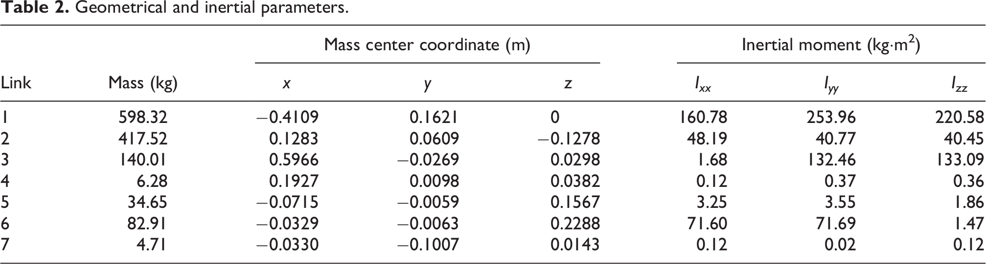
In simulation, two translational joint variables d 1 and d 6 are regarded as undetermined variables. The solution of d 1 and d 6 is optimized based on numerical method. The joint variables θ 2, θ 3, θ 4, θ 5, and θ 7 that are the function of d 1 and d 6 are then determined. Table 2 gives the geometrical and inertial parameters of the robot. When the robot moves along the trajectory as shown in Figure 3, the inverse kinematics is found. Figure 4 shows the joint positions along the trajectory, which changes smoothly. Besides, by taking these positions to calculate the forward kinematic, the error is around 10−15 m. Therefore, our two-step inverse kinematic solving method is effective and accurate.
Geometrical and inertial parameters.

Motion trajectory.

Joint positions.
Based on the dynamic model, the driving forces of active joints are shown in Figure 5(a) when the robot moves along the trajectory shown in equation (21). In order to validate the dynamic model derived by Newton–Euler method, the dynamic model is also derived by the Lagrangian method. When the robot also moves along the trajectory shown in equation (21), the driving forces are computed based on the model derived by the Lagrangian method, as shown in Figure 5(b). One may see that the driving forces derived from two modeling methods are consistent, which shows that the dynamic model is effective.
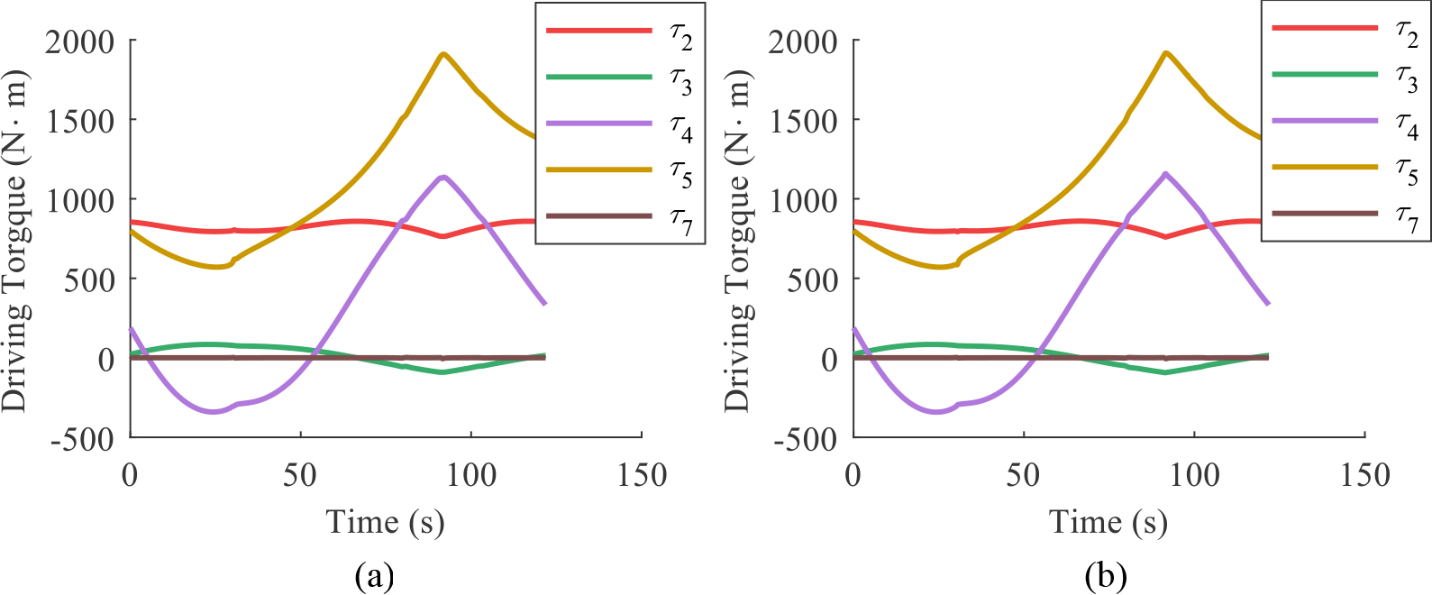
Driving torques of revolute joints: (a) Newton–Euler method and (b) Lagrangian method.
Linearized dynamic model
For the application of dynamic parameter identification, it is necessary to write the dynamic model into the linear form. For the 7-DOF spray-painting robot, there are 70 dynamic parameters, that is, 7 parameters of mass, 21 parameters of the center of mass, and 42 parameters of inertia. Denote the inertia matrix of the ith link with respect to Oi
in Oi
-XiYiZi
by

where
Substituting equation (22) into equation (18) yields

Therefore, equation (19) can be rewritten in a linearized form with respect to

where


in which

Equation (24) can be rewritten in a matrix form as

where

By taking the relations of

where

where

where

and
Effect of telescopic forearm on dynamics
Inertial load and gravitational load
Since the studied robot can paint very large workpieces, a long forearm is required. However, the long link will also have associated problems such as large joint load, low stiffness, and vibrations. Thus, a telescopic forearm is introduced to adjust the workspace. It is obvious that the dynamic characteristics of the robot changes with the length of the telescopic forearm. Since the robot is redundant, the robot has many motion modes for a given painting task. When the painting workspace can be achieved, the robot can work with better dynamic characteristics by adjusting the length of the telescopic forearm. Thus, it is important to study the effect of the telescopic forearm on the robot dynamics.
According to the kinematics derived by Newton–Euler method in the previous session, the velocity of the mass center and angular velocity of the ith link can be written as

where
The dynamic model of the 7-DOF robot can be rewritten as

where
In painting applications, the velocity of the end effector is not fast. Thus, the velocity term is omitted because it has little contribution to the dynamics. The inertial matrix
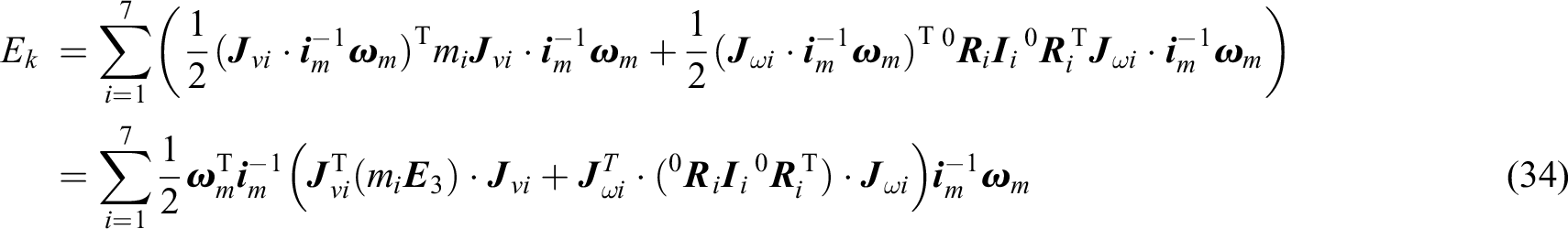
Since the robot has rotational joints and translational joints, the elements in the inertial matrix have different dimensions. It is necessary to make the elements have the same dimension. Considering that the kinematic energy of the robot is
Let the transmission ratio from servomotor to the joint be i
1, i
2,…, i
7 and

Substituting equation (32) into equation (30) yields

where
The kinematic energy of the robot can be expressed as
Thus, the inertial matrix with respect to the rotational velocity of the servomotor can be expressed as

Let Mmij
be the ith row and jth column of

where Mmi
is the sum of the ith-row elements in
Numerical simulation
When the telescopic forearm ranges from its lower length to its upper length, the average inertial load and gravitational load in the joint space are used to consider the effect of the telescopic forearm on the inertial load and gravitational load. It can be observed that the inertial matrix and gravitational matrix are related to the robot orientation not to the translation motion of the first joint. Thus, the average inertial load and gravitational load in the joint space can be expressed as


where θiu and θil are the upper and lower rotational limits of the ith joint.
Since MATLAB cannot directly calculate multiple integrals, equations (37) and (38) are calculated by the Monte Carlo method in this article. The detailed algorithm can be described as: (1) For the telescopic forearm, assign the coordinate value d
6 of the sixth joint a series of values with an equal interval and the algorithm will proceed to the following steps with a given value of d
6. (2) Assign the other six joints random values within their joint limits to form a joint vector
The algorithm to calculate

The transmission ratio and joint limit are shown in Table 4. It can be seen that joints 1 and 6 are translational joints and the transmission ratio has dimension. Joint 1 is a gear-rack drive, the diameter of the gear is 150 mm and the reduction ratio is 40. Joint 6 is driven by servomotor via ball screw, the pitch of the screw is 25 mm, and the reduction ratio is 10.
Transmission ratio and joint limit.

By conducting several rounds of experiments, several sets of data are obtained. Due to the randomness of the Monte Carlo method in choosing

Inertial load of joints: (a) first joint, (b) second joint, (c) third joint, (d) fourth joint, (e) fifth joint, (f) sixth joint, and (g) seventh joint.
Figure 7 shows the relationship between the average gravitational load and d 6. The gravitational load of joints 1 and 2 is zero and the gravitational load of joints 3 and 4 increases with the length of telescopic forearm. The gravitational load of joints 5, 6, and 7 fluctuates with the length of telescopic forearm and does not obviously increase or decrease. Since joint 1 is connected to the base and the driving force direction of joints 1 and 2 are perpendicular to the gravitational direction, the gravitational load of joints 1 and 2 are zero. Thus, when the length of the telescopic forearm is increased, the inertial load and gravitational load of the joints change in a similar trend.

Gravitational load of joints: (a) first joint, (b) second joint, (c) third joint, (d) fourth joint, (e) fifth joint, (f) sixth joint, and (g) seventh joint.
Taking the inertial load and gravitational load as the dynamic load, the dynamic load of joints 2, 3, and 4 increases greatly with the length of telescopic forearm, and the dynamic load of joints 1, 5, 6, and 7 does not increase or decrease obviously. If the motion planning of the 7-DOF redundant robot is considered, it is better to reduce the length of the telescopic forearm to reduce the dynamic load of the joints. Namely, d 6 should be as small as possible. Therefore, this work is very useful for the control and application of the 7-DOF spray-painting robot.
Conclusions
The kinematics and dynamics of a 7-DOF robot with a telescopic forearm for the spray-painting of large workpieces is investigated. A novel two-step inverse kinematic solving method is proposed to find the solution of the redundant inverse kinematics. The inverse solution for five joints that ensure the end-point position of the painting gun is found by numerical means while the analytical solutions of the other two joints are determined by analytical means. The dynamic model is derived and written in a linear form with respect to the dynamic parameters for the application of dynamic parameter identification. Two indices revealing the average inertial load and gravitational load in the joint space are proposed to evaluate the effect of the telescopic forearm on the dynamic load. Simulation results show that the dynamic load of joints 2, 3, and 4 increases greatly with the length of the telescopic forearm, and the dynamic load of joints 1, 5, 6, and 7 does not change significantly. Specifically, the gravitational load of joints 1 and 2 is always zero regardless of the length of the telescopic forearm. As the length of the telescopic forearm increases, the inertial load and gravitational load of joints 3 and 4, and the inertial load of joint 2 increase greatly, the inertial load and gravitational load of joints 6 and 7, the inertial load of joint 1 and the gravitational load of joints 5 fluctuate, and the inertial load of joint 5 slightly increases. If the motion planning of the 7-DOF redundant robot is considered, d 6 should be as small as possible. This work is helpful for the motion planning and control of the 7-DOF spray-painting robot with a telescopic forearm.
Footnotes
Declaration of conflicting interests
The author(s) declared no potential conflicts of interest with respect to the research, authorship, and/or publication of this article.
Funding
The author(s) disclosed receipt of the following financial support for the research, authorship, and/or publication of this article: This work was supported by the National Natural Science Foundation of China (grant nos. 52375502 and U23B20103) and EU H2020 MSCA R&I Programme (no. 101022696).