
Abstract
A new applicable sitting/lying lower limb rehabilitation robot is proposed to help stroke patients. It can realize the sitting/lying training postures to fit people in all the rehabilitation stages. Based on the modularization design, the movable seat can be separated from and grouped into the lower limb rehabilitation robot, which is convenient for patients to sit down. As the most important part of lower limb rehabilitation robot, the mechanical leg design theory is introduced in detail. According to the physician clinical suggestions, a new trajectory planning method is proposed based on the dual quartic polynomial interpolation method. It could realize the adjustment of each joint maximum velocity during the training on account of patient recovery. The accelerations of the joints at target position equal zero, which will reduce impact loads on the patients damaged leg. Also, the dwell time the joints staying at the target angular positions can be increased. Those advantages make the lower limb rehabilitation robot more suitable for stroke patient passive training. Combined with the virtual reality technique, a specific motion-playback scene is designed to improve the patient enthusiasm in the training. Finally, a preliminary experimental trial has been conducted to demonstrate the design of the prototype, the motion-playback scene, and the trajectory planning method feasible.
Introduction
According to the statistics of the World Health Organization (WHO), the world population of people over 60 will be double by 2050. Elderly people are the high-risk group of stroke and most stroke patients lose their walking ability.1,2 The treatment for the limb motor dysfunctions requires a lot of manpower, material, and financial resources, but these resources are still not enough.3,4 Robotic systems have been applied to the rehabilitation robot field.5–11 Several lower limb rehabilitation robots have been developed.12–15 They can be divided into single-degree-of-freedom rehabilitation robots, wearable rehabilitation robots, suspended rehabilitation robots, and sitting/lying rehabilitation robots. Because the effect of single-degree-of-freedom robots has a poor training effect, wearable robots need the patient having the abilities to walk independently, and suspended robots are tedious for the patient to wear; this article just discusses the sitting/lying rehabilitation robots. Yildiz University of Science and Technology in Turkey made a sitting/lying gait trainer, Physiotherabot, helping patients do passive training and active training. 16 M Bouri et al. developed a new rehabilitation robot, Lambda. Based on two translational articulations and one rotational for the ankle mobilization, the patient’s hip, knee, and ankle can conveniently be mobilized in order to carry out rehabilitation, fitness, or high-level sport training. 17 Carleton University made a virtual gait rehabilitation robot (ViGRR) for bed-ridden stroke patients. It can provide the average gait motion training as well as other targeted exercises such as leg press, stair stepping, and motivational gaming. 18 And this article put forward a new sitting/lying lower limb rehabilitation robot, LLR-Ro. Compared with the above sitting/lying rehabilitation robots, the mechanism design of LLR-Ro has several merits. It could adjust the leg length by motor. The torque sensors are installed at the joint axis to acquire the mechanical leg joint torque more accurately. And LLR-Ro has a movable seat to transfer the patient without the assistance tool.
The stroke patients’ recovery process contains three stages, which are flaccid paralysis stage, spasm stage, and recovery stage. During the flaccid paralysis and spasm stage, patients receive rehabilitation training in a passive state to improve muscle tension and restrain abnormal movement. 19 Then the passive training of the rehabilitation robot is designed to help the patient limb moving on the desired trajectory and realizing the stroke patient limb joint motion within the designated scope.20,21 Therefore, the generation of the desired trajectory for the robot passive training has been the research hotspot.22–24 At present, most of researchers just discuss the normal gait of healthy subjects, and the relevant normal gait data are used as the reference database for trajectory planning.25,26 Rosati et al. 27 address a trajectory planning of a rehabilitation mechanism, which is defined in both the Cartesian space and joint space. The National Taiwan University Hospital-ARM (NTUH-ARM), 28 a rehabilitation robot proposed by National Taiwan University, is defined trajectory with cubic spline method. In order to obtain a smooth human machine interaction in different phase of gait cycle, an adaptive trajectory control for the rehabilitation device is proposed. 29 NEUROBike is developed with ellipse-based trajectories to obtain different range-of-motion at the leg joints. 30 However, in the flaccid paralysis and spasm stage, each joint of patient needs to reach the movement limit gradually, and then the range of each joint need be growing to realize normal people’s gait. This article proposes a new path planning method. Compared with the above trajectory planning methods, it can not only achieve the position continuity, velocity continuity, and acceleration continuity, but also realize training target joint angle efficiently through the adjustment of the robot joint acceleration. It has a unique slow-motion feature near the target joint position.
Meanwhile, with the development of the high-level sensing and visualization technology, the study on virtualization therapy in rehabilitation robots has also become the research focus. 31 Rehabilitation treatment using a virtual environment provides various training feedback.32–34 Based on the characteristics of the sitting/lying rehabilitation robot, a new virtual reality scene is designed for LLR-Ro.
The innovative design of the LLR-Ro
Based on the theory of innovation and modularity, LLR-Ro (as shown in Figure 1) is consisted of the movable seat, touch-sensitive display, control box, left leg mechanical module, and right leg mechanical module. There are four universal wheels under the base of the movable seat, so the movable seat could separate from and group into LLR-Ro, which is convenient for the patient to sit down. The angle of the backrest of the movable seat can also be adjusted to satisfy patients with different recovery stages. Patients in early stage can lie on the seat while in the middle and later stage sit on the seat. The mechanism legs are the most important part in the whole prototype. It can alter their length electronically to match patients with different heights from 1.5 to 1.9 m. The mechanism leg consists of six parts as shown in Figure 2. (I) is the hip joint drive components. The high-speed shaft side is driven by synchronization pulley and the low-speed output side is driven by gear mechanism as shown in Figure 3. It also has the torque sensor and absolute position encoder installed on the hip joint axis. The design of the hip joint components could reduce the position and torque measurement error. (II) is the thigh assembly. It is integrated by the knee joint drive chain (shown in Figure 4) and the thigh length auto-adjustment (as shown in Figure 5). The high-speed shaft side is also driven by synchronization pulley and the low-speed output side is driven by gear mechanism. The torque sensor is installed on the knee joint axis. In order to make the structure compact, the absolute position sensor is driven by rope wheel. The theory of the thigh length auto-adjustment is that one end of the pushrod is connected with the rack and the other end is connected with the relative moving part. Meanwhile, the rail is installed on the rack and slider installed on the moving part, so when the length of the pushrod (electric drive pusher) is changed, the moving part is in motion with respect to the rack. In Figure 2, (V) is the plantar plate assembly. This design can acquire the torque based on the force signal the patient’s foot exerting on the robot. The torque acquired theory is shown in Figure 6. When the pull-push sensor gets the plantar force

The innovative design of the LLR-Ro.

The structure composition of the mechanism leg. (I) is the hip joint drive components; (II) is the thigh assembly; (III) is the structure design of the knee joint; (IV) is the calf assembly; (V) is the plantar plate assembly; (VI) is the ankle joint drive components.

The hip joint drive chain.

The knee joint drive chain.

The theory of the thigh length auto-adjustment.

The theory of the ankle joint torque acquired.
The design of virtual reality scenes for LLR-Ro
Combined with the virtual reality technology and the injury degree of patients, one of virtual reality scenes used in the passive training mode is proposed, named motion-playback scene (MPS). In MPS, the motion of the patient lower limb will be mapped on the display screen. This design is also bonded with the angle of the backrest of the movable seat. MPS in the sitting posture will be adapted for patients with the sitting ability and MPS in the lying posture for patients only lying on the sickbed as shown in Figure 7. During the training, the screen of the LLR-Ro will synchronously show the training time, the frequency of training, the angular position and angular velocity of joints, and so on. The background music would also be played in the game to make the patient immerse in the rehabilitation training.
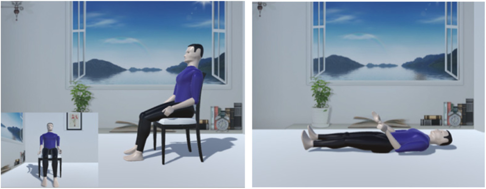
The motion-playback scene.
C-script is adopted to realize the movement effect of the virtual character, including the main control script and virtual character motion script. The flowchart of the main control script is shown in Figure 8. The main control script will build the communication between the virtual character and LLR-Ro, obtain LLR-Ro joint angle values, and transfer to the virtual character motion script. However, the scene rendering takes up a lot cyber resource, which will influence the control precision severely. So the scene is displaced on the other computer. These two computers should be contacted through transmission control protocol/internet protocol (TCP/IP) protocol. Besides, the virtual reality scenes are designed through C code and the LLR-Ro control software is built through LabVIEW, a client socket needs to be created to communicate data. The virtual character motion script is primarily used to obtain the LLR-Ro joints current angle values through main control script and follow the LLR-Ro joints motion.
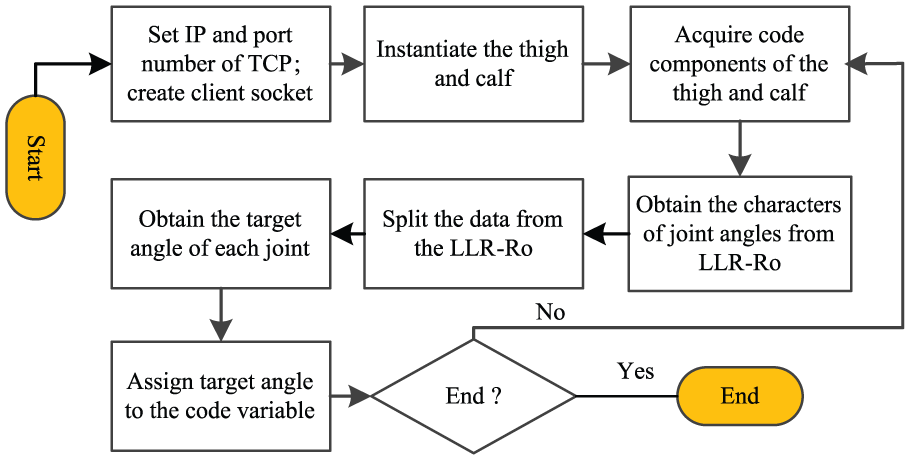
The flowchart of the main control script.
The dual quartic polynomial interpolation method used for trajectory planning
Based on the quartic polynomial interpolation method, a new dual quartic polynomial interpolation method is proposed for trajectory planning. It can be used at the regular graphic trajectories planning of the end point B at the mechanism leg, as shown in Figure 9. Thereinto, O, A, and B represent the center of the hip joint, the knee joint, and the ankle joint in the sagittal plane, respectively. Positions ①, ②, and ③ are the start position, the waypoint position, and the end position of the training, respectively.

The mechanism leg in the rectangular coordinate system.
While the greater the parameters

From position ① to position ② and from position ② to position ③, an equation set is supposed

where

To verify the dual quartic polynomial interpolation method reasonable, a simulation is performed as below. The end point of the leg mechanism moves along a circular arc trajectory as shown in Figure 10. Thereinto,

The circular arc training trajectory.
By equations (2) and (3), we could obtain the curves of the angular positions

The curves of the kinematic parameters of the hip joint during

The curves of the kinematic parameters of the knee joint during

The curves of the theoretical trajectory and planning trajectories during

The velocities along the x-axis and y-axis during
From Figures 11–14, the angular velocity curves of the hip and knee joint are smooth and the acceleration curves are also continuous and smooth, which meets the design goal of the robot. The most major advantage of the method is that the maximum speeds of all the joints will be increased when the distance
The LLR-Ro passive training control strategy
Mechanical legs of LLR-Ro have good dynamic property and static property, as they are moving in a slow speed. The object of the LLR-Ro passive training control strategy is to obtain the mechanical leg moving on the desired trajectory, while joint velocities and accelerations could meet the lower limb rehabilitation theory. Based on the trajectory planning with dual quartic polynomial interpolation method, combined with the proportion integration differentiation (PID) control algorithm, the LLR-Ro passive training control strategy is built. The passive training control flowchart is given as in Figure 15.

LLR-Ro passive training control flowchart.
Based on the man–machine interaction on the touch screen, the length of LLR-Ro mechanical legs could be adjusted equaling with the patient legs’. Then through the mechanical trajectory selection and discretization processing, the joint desired velocities are obtained. The difference between the desired velocity and actual velocity will be sent to the PID algorithm controller. Meanwhile, the actual velocity is also adopted in the virtual reality synchronous display. Finally, the patient rehabilitation training status will be displayed on the touch screen for the rehabilitation physician to evaluate.
The LLR-Ro preliminary experimental trial
The feasibility of the design of the prototype, the virtual reality scene, and the dual quartic polynomial interpolation method are verified through this experiment. In order to prove the universality of the dual quartic polynomial interpolation method for LLR-Ro to make the regular graphic trajectory planning, the experiment will adopt a linear trajectory. The trajectory is expressed through

The experiment process during the

The curves of the kinematic parameters of the hip joint during

The curves of the kinematic parameters of the knee joint during

The curves of the theoretical trajectory and experiment trajectories during
From Figure 19, the end point trajectory errors at the start are much larger than the errors at the end. That is because the heavy mechanism leg produces the vibration at the initial position. The other kinematic maximum errors are obtained during the
The kinematic maximum errors during

From Figure 16, the mechanism leg moves synchronously with the leg of the virtual character. As it is difficult to demonstrate the treatment effect of LLR-Ro with the MPS, the volunteer is asked to answer a questionnaire. The results of training without and with virtual reality scenes bring the volunteer different psychological states. The volunteer is more willing to participate in rehabilitation training with the virtual reality scene. In future, the clinical test will be conducted to verify the effectiveness and universality of LLR-Ro with MPS.
Conclusion
A new sitting/lying LLR-Ro is proposed to help people with lower extremity injuries. It can realize the sitting/lying training postures to fit people in all rehabilitation stages, including the early, the middle, and the late rehabilitation stages. Combined with the virtual reality technique, a specific MPS is designed to improve the training process interest and patient enthusiasm in rehabilitation training. According to the clinical rehabilitation theory and the physician suggestions, a new trajectory planning method is proposed. It can realize the adjustment of each joint maximum velocity during the training. The accelerations of the joints at target position equals zero, which will reduce impact on the patients damaged leg. The dwell time the joints staying at the target angular positions can also be increased. It has a unique slow-motion feature near the target joint angle. Those advantages make the LLR-Ro more suitable for clinical requirements. This article has important scientific significance and theoretical value in improving and developing the sitting/lying LLR-Ro theory.
Footnotes
Handling Editor: Assunta Andreozzi
Declaration of conflicting interests
The author(s) declared no potential conflicts of interest with respect to the research, authorship, and/or publication of this article.
Funding
The author(s) disclosed receipt of the following financial support for the research, authorship, and/or publication of this article: This work was supported by China Science and Technical Assistance Project for Developing Countries (KY201501009) and National Construction High Level University Government-Sponsored Graduate Student Project (certificate no. 201608130106).