
Abstract
This article studies the multi-layer and multi-pass welding of the circumferential weld in the thick pipe welding of an aviation enterprise, based on the static characteristics of the welding arc, through data calculations and experiments to verify the relationship between arc voltage and arc length, proposes to use the arc voltage controller to accurately adjust the arc voltage in real time, improve the welding stability, use the welding torch wiggler to expand the welding fusion width, meet the adaptive adjustment of the wide weld, and build the main control system based on programmable logic controller (PLC) control. Integrating all subsystems and put them into the actual production of the enterprise, significantly improves the production efficiency of parts welding, reduces welding defects, and improves the quality of aviation parts.
Introduction
Automatic welding has shown wide application in manufacturing industry because of its advantages including good stability and high efficiency. 1 –5 At present, the production of automatic welding is mostly limited to regular welds and components with small deformation. For joining of thick pipe wall structure, multi-layer and multi-pass welding process is required, and the welding deformation needs to be accurately controlled. 6 –8 There is great instability in conventional welding quality, which is prone to welding defects.
Through the investigation and research on the welding of the rotating shaft of an aviation enterprise, this article creatively uses the arc voltage controller and the welding torch wiggler, also designs a set of special welding system by integrating other components, so as to make the welding process always in the optimal state, effectively control the welding deformation, and realize the automatic welding of annular wide and deep welds.
The target product of the welding system is an aviation rotating shaft, as shown in Figure 1. It is an assembly weld seam located between shaft shoulder and rotating shaft which requires one-time assembly and welding completion. The weld quality reaches the grade II weld inspection standard of the national military standard.
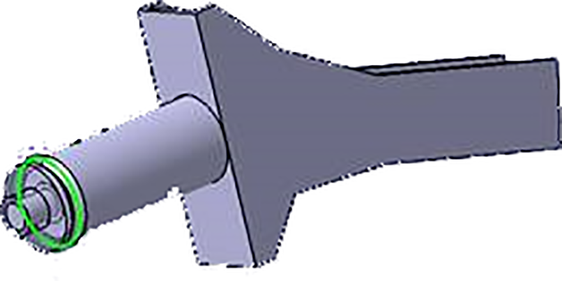
3D schematic drawing of target products.
According to the requirements of the enterprise, the system operation mode is divided into two types: (1) Manual mode: All the stages including robot teaching and programming, welding parameters modification and welding process adjustment are under manual operation. (2) Automatic mode: The entire welding process is carried out under automatic control. 9 –13 When the preparation before welding is completed, the parameter settings are confirmed to be correct, the system will switch to automatic mode, and operators can start or stop the workstation via the button operation box.
System composition and layout
The welding system is mainly composed of welding machine tool system, welding power supply system, welding auxiliary system, and integrated control system. 14 –18 The welding machine tool includes bed, positioner, tooling fixture, operator, and so on, and the welding auxiliary system includes welding torch swinger, arc voltage controller, and so on. Integrated control system includes electrical control cabinet, touch screen, operation panel, control cable and trunking, and so on. The welding power supply system includes TIG welding power supply, wire feeder, water cooling system, TIG welding torch, communication interface, welding cable, and so on. The equipment adopts combined structure, and each component is connected into a system through electrical control cable, welding cable, trunking, and gas circuit system, which is convenient for installation, commissioning, and transportation.
Ontology structure design
The welding system is mainly composed of horizontal circumferential seam welding machine tool, welding auxiliary system, integrated control system, and welding power supply system. The horizontal circumferential seam welding machine tool includes bed, positioner, tooling fixture, welding slide, and so on. The welding auxiliary system includes welding torch swinger, arc voltage controller, and so on. Integrated control system includes electrical control cabinet, touch screen, operation panel, control cable and trunking, and so on. The welding power supply system includes TIG welding power supply, hot wire power supply, wire feeder, water cooling system, TIG welding torch, communication interface, welding cable, and so on. The equipment adopts combined structure, and each component is connected into a system through electrical control cable, welding cable, trunking, and gas circuit system, which is convenient for installation, commissioning, and transportation.
Welding machine tool system
The special welding machine is mainly for circular arc girth welds. The main components of the welding machine tool include bed, positioner, support platform, three-axis motion system, and so on.
The use process of welding system is as follows: When working, place the workpiece against the support platform; Shake the handle on the support platform to lift the workpiece, the three-jaw chuck of the positioner clamps the tail end of the workpiece, and adjust the height of the support platform; Lower the welding torch and align it with the weld center through manual adjustment; After arc striking, the swinging device drives the arc voltage controller to swing left and right through the control of the motor, and the positioner holds the workpiece to rotate synchronously to complete the welding of the workpiece.
Positioner structure
The overall structure of the positioner is shown in Figure 2. To ensure the coaxiality between the rotating shaft of the positioner and the rotating shaft of the motor reducer and the timely response of the positioner, the following design is adopted: The motor reducer is installed on the bearing seat. The bearing seat is processed according to the matching requirements given by the reducer. It is processed in place after clamping at one time during the manufacturing process. The motor reducer adopts flange output shaft, and the transmission shaft is screwed with the motor reducer. The end of the transmission shaft is connected with the chuck through Morse taper to eliminate the rotation clearance caused by the key connection.
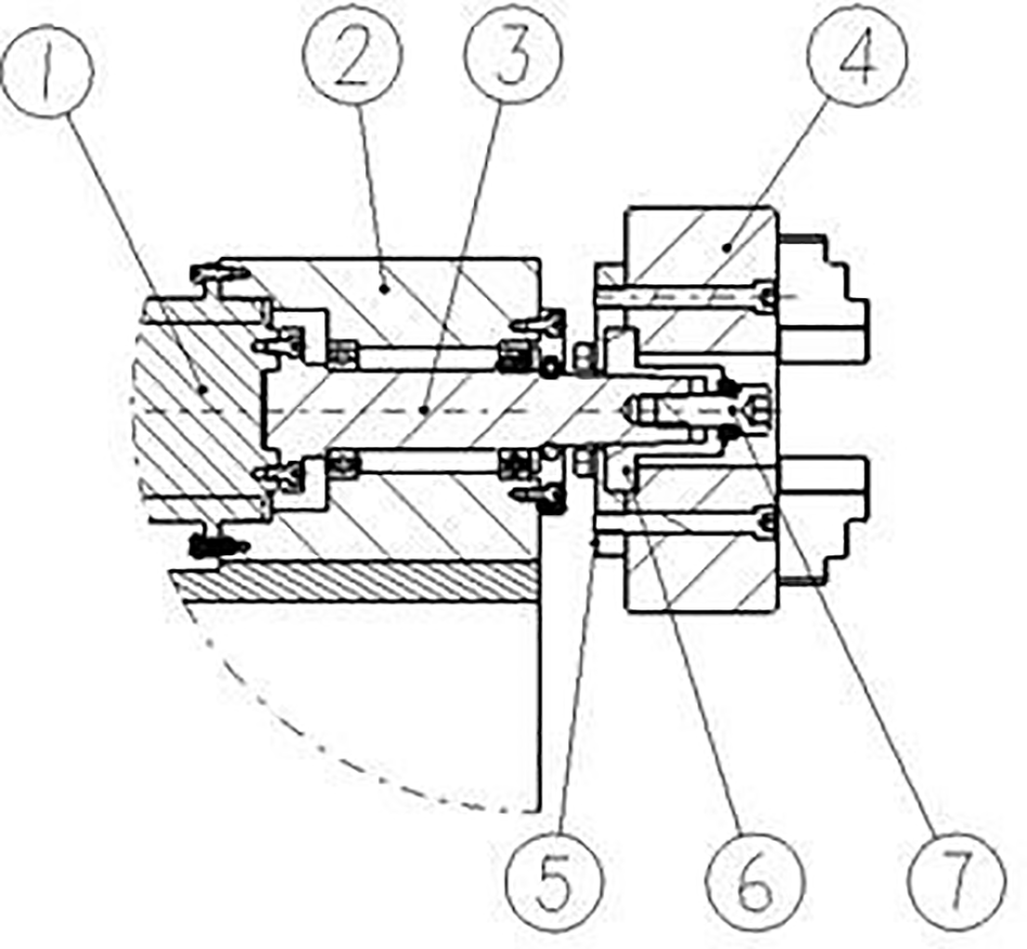
Composition of positioner system. 1. motor and reducer, 2. bearing seat, 3. transmission shaft, 4. chuck, 5. chuck mounting plate, 6. flange, and 7. screw.
Some workpieces clamped by the chuck need to be heated to more than 200°C and processed at this temperature. Therefore, it is necessary to consider the axis deviation caused by uneven heating. When selecting the chuck, the four-jaw single-action chuck is used to clamp the heated workpiece. For unheated workpieces, directly clamp them with three-jaw chuck.
To facilitate the quick change of chuck, a set of chuck mounting plates are made for three-jaw chuck and four-jaw chuck, as shown in Figure 3. The chuck mounting plate is designed and manufactured respectively according to the installation requirements of three claws and four claws, and the flange is the same. 19 –23 During installation, the flange is matched with the transmission shaft through Morse taper. After screw 7 is tightened, the flange and the transmission shaft are locked. When changing the chuck, just remove screw 7 in Figure 2. The holding range of three claws and four claws are 4.200 mm and 10.250 mm respectively.

Installation diagram of chuck. 1. three claw mounting plate, 2. flange, 3. three claws, 4. four claw mounting plate, 5. four claws.
Support platform
The support platform has two degrees of freedom and can move along the Y-axis and Z-axis directions. The power input is manual and can be used to support the diameter 10–240 mm, long 200–1400 mm workpiece. The linear guide rail is used as the moving pair in the Y-axis direction and is equipped with a clamp. When the platform is manually moved in place, the clamp can be tightened to lock the support platform in the Y-axis direction. Worm gear lifting mechanism is adopted in the Z-axis direction, and two linear bearings are used as guidance. The worm gear and worm transmission ratio is 1:28, the lead is 4 mm, the worm stroke per revolution is 0.143 mm, and the maximum lifting force and tension are 10 kN. The Z-direction movement needs fine adjustment when adjusting the support height, so the model with smaller stroke per revolution is selected.
Three-axis motion system
The three-axis motion system is convenient to manually adjust the position of the welding torch before welding. The three-axis motion system makes the movement of the welding torch more flexible. The Z-axis motion adopts linear module, and the X-axis motion adopts linear guide rail and gear rack transmission. X-axis stroke 150 mm, load 20 kg; Y-axis stroke 1400 mm, load 200 kg; the stroke of Z-axis is 800 mm and the load is 50 kg.
The slide table is designed as follows: The linear guide rail and rack are arranged vertically. To ensure the perpendicularity of the two planes of the sliding table, the sliding table is bolted with hinged hole bolts to avoid deformation caused by welding. As the center of gravity of the whole motion system is forward, the wire disc is installed at the rear of the sliding table to play the role of counterweight, so that the center of gravity of the whole sliding table falls near the linear guide rail. The installation position of the traveling motor is adjustable to eliminate the fit clearance of the gear rack.
Bed structure
The bed is the frame of the dedicated machine, which is used to install the components of the system, 24 –28 as shown in Figure 4. The whole bed is welded with 80 × 80 and 100 × 100 square steel, and the installation part is pasted with steel plate. After welding, the bed shall be artificially aged to eliminate welding deformation. Finish machining the mounting surface after aging to ensure the assembly accuracy of all parts. Six anchors are installed at the six corners of the bed, which is convenient for the special machine to adjust the level and make the machine tool placed horizontally.
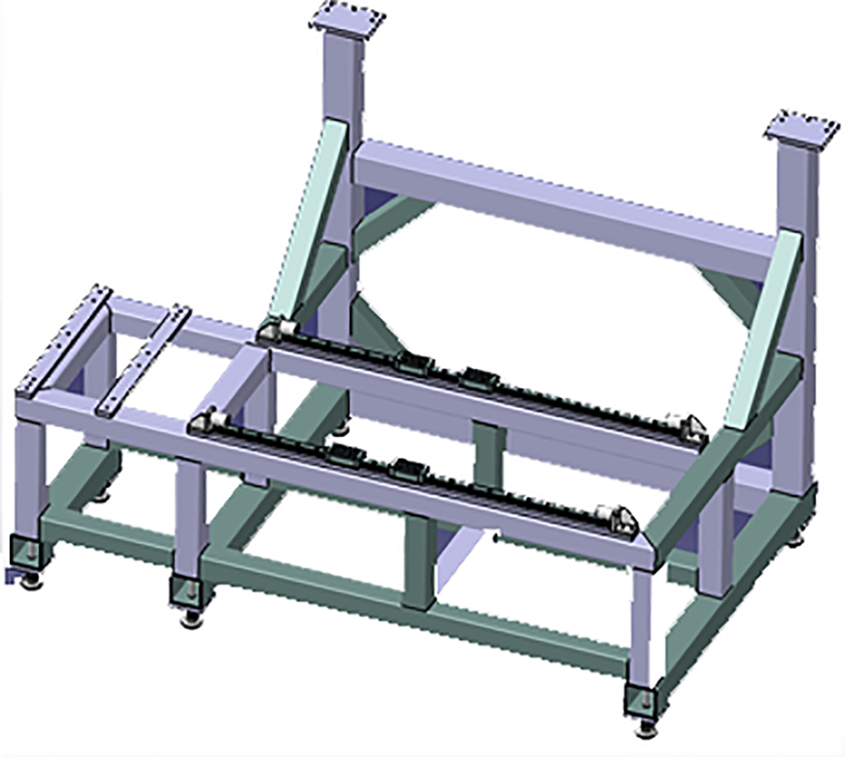
Schematic diagram of bed structure.
Welding system
The function of the welding system is to control the welding torch, wire feeding mechanism, cooling water tank, electricity, gas, and other auxiliary parts through the welding power supply and adjust the parameters such as voltage and current, wire feeding speed, water flow, and air flow speed to realize the reasonable welding of the welding torch. The welding system cooperates with the circumferential seam system to realize the welding of the workpiece.
According to the welding parameters of automatic argon arc welding shown in Table 1, the material thickness is 5 mm and the welding current is 270–290 A, which is higher than 5 mm. Generally, multi-layer welding is used as the basis for selecting welding power supply according to the welding demand. The TIG welding materials of an aviation enterprise are mainly ferrous metal structure, aluminum alloy metal, and there are many 8 mm and 10 mm pipes. DC pulse argon arc welding is suitable for welding stainless steel, copper, titanium, carbon steel, and other materials, and AC is suitable for welding aluminum, magnesium, aluminum bronze, and other metals and their alloys with strong welding activity. 29,30 Therefore, the scalability of the system is fully considered when selecting welding power supply. Select AC/DC welding power supply.
Welding parameters of automatic argon arc welding.

If it is higher than 5 mm, multi-layer welding is generally adopted. According to the comparison of welding performance, stability, and price, IDA’s welding system is selected, and the AC/DC welding power supply Tetrix 352 with a temporary load rate of 100% and a welding current of 350 A is selected as the welding power supply. The detailed technical parameters of Tetrix 352 are shown in Table 2.
Tetrix 352 activar parameters.

After demonstration, the robot water-cooled welding torch ABITIG MT500 of Binzel company is selected. The main technical parameters of the welding torch are shown in Table 3. The high-frequency arc striking method is adopted. With the help of the high-frequency arc striking device in the TIG welding machine control device, when the tungsten electrode of the welding torch is 2–4 mm away from the workpiece surface, when the microswitch of the welding torch is pressed, the arc will ignite quickly.
Welding torch ABITIG MT500 parameters.

For the installation of the welding torch, as shown in Figure 5, install a welding torch support on the welding torch and install it on the flange of the welding torch wiggler. Due to the high temperature of the welding torch during welding, the cooling water tank is used to cool the welding torch during arc welding.

Welding torch support.
The control of wire feeder is synchronized with the welding system and installed behind the X-axis and Z-axis to facilitate the transportation of welding wire.
According to the requirements of shielding gas used in TIG welding, 99.9% pure argon is used in the project. The pressure of argon is controlled by the pressure gauge on the argon cylinder. The argon cylinder is directly connected to the air inlet of the welding power supply, and then connected to the welding torch from the air outlet of the welding power supply. The argon gas supply time is controlled by the welding power supply.
Arc voltage controller
In the process of automatic welding, the arc length is an important factor affecting the welding quality. 31,32 Due to the uncertainty of the change of workpiece surface height and the existence of weld deformation (caused by inaccurate assembly or welding thermal deformation), the distance between electrode and workpiece may change, making the change of arc length uncertain.
Arc voltage (Ua ) and arc length (L) have a regular relationship, the calculation formula is as follows

In formula (1), UC is the cathode pressure drop, UA is the anode pressure drop, in the case of the same welding current, electrode material, protective atmosphere, and other conditions, UA is a constant value; E indicates the arc column pressure drop per unit length, that is the arc column potential gradient, is a constant determined by the protective gas and environmental conditions.
The following graph of arc pressure versus arc length can be further obtained through experimental tests.
From Figure 6, the relationship between arc voltage and arc length also shows a good proportional relationship between Ua and L.
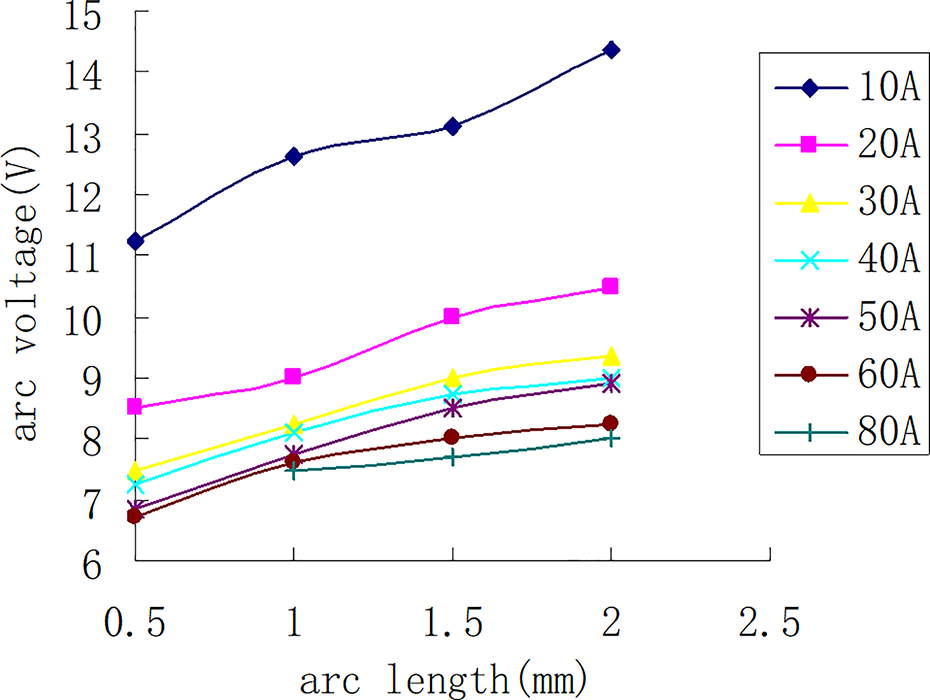
Relationship between arc pressure and arc length.
According to the requirements of annular wide and deep weld, the weld groove is Y-shaped and the blunt edge is 5 mm. The arc voltage can be adjusted by the arc voltage controller. The quality of annular wide and deep weld is a secondary weld with high requirements. Therefore, the use of arc voltage controller can effectively control the arc voltage fluctuation in the welding process. TIG welding is adopted for annular wide and deep welds. The relationship between TIG welding current and welding voltage is GB standard, the formula is as follows

In formula (2), U is the welding voltage (V) and i is the welding current (A). When the current is greater than 600 A, the voltage protection 34 V is constant. The welding voltage range is 10–22.4. The error of arc voltage shall be less than ±0.1 V.
As shown in the system diagram of arc voltage controller in Figure 7, the arc voltage controller developed in this article includes drive box, actuator, and communication channel. The actuator is driven by DC servo motor and spherical thread lead screw. The spherical nut drives the sliding plate. The control system uses the linear relationship between arc pressure and arc length. By extracting the arc voltage signal and sending it to the automatic voltage control (AVC) controller, the data processing (comparing with the given arc voltage value, converting the deviation value into the direction and strength of the drive signal output from the vertical motion mechanism of the torch), the AVC controller sends a command to the vertical motion mechanism of the torch. The AVC controller issues a command to the welding torch vertical motion mechanism to adjust the arc length according to the processing result. During welding, the control panel displays the set value and current value of welding voltage and carries out real-time control. The operator can manually intervene the welding voltage at any time and can also lock and recover at any time. The arc length controller is also locked in the pulse base value and arc ending stage.

System diagram of arc voltage controller.
Welding torch wiggler
According to the requirements of annular wide and deep weld, the weld groove form is Y-type, the blunt edge is 5 mm, the groove angle range is 60°–90°, and the groove width is 15–27 mm. To ensure the weld penetration, the welding torch must swing, that is, the welding torch must be clamped on the swing device. When the positioner rotates, it must swing in a straight line in the direction of the weld joint width.
The welding torch wiggler of the project includes a communication/drive module and an actuator. The actuator comprises a stepping motor, a coupling, a linear module, a welding torch holder, and a protective cover. As a part of the welding program, the swing device is controlled through the program. When the operator uses PLC to prepare the welding program, the swing width, swing center, swing speed, and residence time on both sides can be set (left and right can be set respectively). During edge dwell, there is an auxiliary circuit signal output, which can be used to drive other auxiliary equipment.
Before welding, the operator shall test run the wiggler to see whether the swing parameters are appropriate. During the welding process, the operator can manually intervene the swing at any time, or lock it at any time and restore it at any time. The welding torch wiggler required in this project shall also include an automatic return function, which can make the wiggler automatically return to the preset swing center each time it is closed. Considering the procurement cost and the simple swing mode required for girth welding, the swing mode is selected as linear swing.
Through the research of this subject and in combination with the project requirements, the welding torch wiggler shall meet the following index requirements: Swing carriage travel: 0–60 mm; Swing speed: 150–1500 mm/min.
Linear module
According to the calculation, the weight of the welding torch and arc voltage controller is 6.8 kg. One set of linear module of Shenzhen Weiyuan GSX50-150-p7 model is selected, with accuracy of P7 level, repeated positioning accuracy of 0.008 mm, rated load of 10 kg, maximum load of 15 kg, self-weight of 2 kg, stroke of 150 mm, effective stroke of 70 mm, combined height of 38 mm, shell width of 50 mm, ball screw diameter of 12 mm, and lead of 5 mm, quantity of sliding table: 1, pre-tightening: 2%, and the motor is installed through the motor base and coupling.
Motor and driver
Considering the cooperation with linear module, the rated load is 15 kg. The 42BYG250BK (000768) stepping motor of Beijing HollySys Motor Technology Co. Ltd is selected. The size and load can be matched with the linear slide rail. The driving voltage is 24 V. The driver control interface is pulse and direction, which can be controlled by PLC. Calculated according to the lead of the matching linear module is 5 mm, the rated load of the motor is 15 kg. The supporting SD-20403 stepping motor driver is selected as the driver, SD-20403 stepper motor driver control signals include common terminal, pulse signal, and direction signal.
Main control system
The main control system controls, manages, and monitors the whole system. The main control box is the control center. PLC controls and manages the whole system, mainly completing the coordinated control of the operator, welding system, human–computer interaction equipment, and operation box. The operation box completes the start, reservation, stop, and other operations of the system and is equipped with start control box, three-color light, and other equipment. The human–computer interaction equipment meets the personalized needs of different users. The human–computer interaction interface can intuitively display various parameters in the automatic welding system on the human–computer interaction interface. The operator can carry out some operations on the whole system, monitor the production process, and ensure that the equipment is in the optimal operation state at all times.
System composition
According to the on-site operation process and the system, this article adopts the linkage mode of operator and positioner to realize the positioning of welding torch and the welding of workpiece. The electrical system control of the project is mainly controlled by PLC. After demonstration, the research group selects OMRON PLC and adopts OMRON PLC position control module to realize four-axis linkage control; OMRON PLC communicates with welding power supply through Ethernet or DeviceNet. The operator operates through the startup box and touch screen, the signals of various sensors in the safety protection mechanism are transmitted to the PLC for processing, the movement of the operator and positioner is controlled through the PLC, the welding parameters are set through the man–machine interface, and the welding parameters are called through the communication between the PLC and the welding power supply.
Communication design
The system uses PLC as the main control unit to connect the input signal of each position sensor and safety grating into PLC for logic control of the system. 33,34 The man–machine interface communicates with PLC through Ethernet interface, which can realize the operation and display functions of backing welding parameters, filling welding parameters, cover welding parameters, number of welding layers, swing speed, welding fault, and other process parameters. The PLC adopts OMRON cj1w-nc414 position control module to control the operator and positioner. The operator communicates with cj1w-nc414 in the form of IO hard wiring to control the linkage of three servo motors. The positioner communicates with cj1w-nc414 in the form of IO hard wiring to realize the position control of the positioner. The arc voltage controller communicates with the welding power supply through IO hard wiring for high and low pulse control. PLC controls the start and stop of arc voltage controller through IO hard wiring. In the swing device of welding torch, PLC uses pulse board to control the stepping motor, which can realize the linear swing welding function of welding torch. PLC and welding power supply use fieldbus DeviceNet module to realize digital communication. Welding current, wire feeding speed, and other parameters can be set directly on the man–machine interface. In the welding process, the job parameter mode of the welding machine is adopted, and the PLC calls different job numbers according to the needs of different welds. Under the condition of continuous arc, the switching of different welding parameters can be realized to meet the needs of different weld positions.
Operation box
A convenient and safe operation box is designed according to the operation characteristics of the special machine for circumferential weld. In this console, you need to press two start buttons at the same time to start the system. In this way, the misoperation of personnel can be effectively prevented and the use safety can be improved. Emergency stop button: Press, the system will enter emergency stop. Pause button: Press, the system will enter pause. Welding restart: after the emergency stop or pause is canceled, press, and the system will continue the work before the emergency stop or pause. Start button: press the start button, and the system will start when the start conditions are met. Manual/automatic button: only when the button is turned to automatic mode can automatic welding be carried out; when the button is turned to manual mode, only parameters, manual operation, and teaching program can be debugged.
Interface
Touch screen is an important channel of human–computer interaction. The touch screen of the system has the following functions: working interface, monitoring interface, welding parameters, alarm interface, and production output.
In the main interface of the work, you can select to enter the operation description, alarm screen, manual interface, and automatic interface. In this interface, there is parameter feedback in welding in the current state, such as welding current, arc voltage, wire feeding speed, welding stroke, and swing speed, and the current welding information can be displayed. There is an inspection feedback signal for the current operation status. When the fault light is on, it indicates that there is a fault at present, and when the safe operation light is on, it indicates that the current operation is normal and there is no fault.
The function of the operation instruction interface is to provide operation safety instructions during the process, mainly including checking whether the equipment power supply and air source are normal when starting up, precautions in manual operation and automatic operation, and operations on the welding platform.
The alarm interface is mainly used to check the fault location and fault information of the system during operation.
Manual interface is also called manual operation box. Its interface includes rotating button, manual control, and main interface display. In the rotating button, the automatic operation can be switched through the rotating button. Manual control includes welding wire (wire feeding and withdrawal), low speed of upper and lower shafts (up and down), low speed of front and rear shafts (forward and backward), low speed of cross beam (left and right), low speed of positioner (forward and reverse rotation), and welding torch swing (forward swing, reverse swing, and swing back to the original point). The main interface display includes position clearing, fault handling, and displaying the number of welding fault codes.
Automatic interface, also known as automatic operation box, can be considered to set the total number of layers, positive welding layer, and pipe diameter, and there are rotating buttons and main interface. Manual and automatic operation can be switched manually by rotating the button. In the main interface, it includes ready button, simulated welding button, start welding button, pause welding button, welding start button, layer reset button, welding parameter setting, and welding wiggler operation setting.
In the welding parameter setting, it mainly includes the parameter setting of the circumferential seam interface, which mainly includes the setting of the total number of layers, the number of positive welding layers, and the pipe diameter. A total of 1–15 welding sections are included. 34 –36 Each welding section includes the settings of welding parameters, welding procedures, wire feeding speed, and welding speed.
The main interface of the welding torch wiggler mainly includes the setting of the total number of layers, the number of positive welding layers, the residence time of (left, right, and middle), and the automatic swing speed. Including welding sections 1–12, each welding section needs to set whether to start and left and right swing settings.
Process experiment
According to the actual needs of enterprises, this article has completed the development of automatic welding system equipment for annular wide and deep welds. The physical drawing is shown in Figure 8. After installation and commissioning, the design requirements and performance requirements put forward by customers have been realized.

Physical drawing of welding system.
Technological process
The welding of annular wide and deep welds adopts multi-layer and multi-pass welding. The actual welding process is divided into three processes: backing, filling, and covering. For backing welding, first use pulse current self-fusion backing (welding wire can be added appropriately) to ensure good fusion forming at the back of the workpiece weld. For filling welding, pulse current is used to continuously add welding wire and swing to fill the gap at the groove for many times until the groove is basically flat with the workpiece surface. For cover welding, pulse current, swing, and add welding wire are adopted, and there is a certain reinforcement on the weld surface to ensure good surface fusion molding.
As shown in Figure 9, arc welding process mainly includes three stages: arc striking, main welding, and arc ending. The welding system stops accurately at the welding starting position, executes the welding instruction, and enters the arc striking stage. 37,38 At this time, it is generally necessary to apply a slightly larger welding current and arc voltage, and the high-frequency arc starter ignites the arc to realize smooth arc striking.

Welding process flowchart.
After detecting the current detection signal, the welding system can start to move and maintain the arc striking current and voltage for a period of time. The welding torch starts to swing and enter the main welding stage. The main welding stage is mainly divided into backing welding, filling welding, and cover welding. In the main welding process, the welding system first performs backing welding with the specified welding parameters. After the primer welding is completed, the welding torch will automatically lift and continue to call the welding parameters of the next section for filler welding. Finally, lift the welding torch and call the cover welding parameters. When the welding system stops accurately at the welding end position and executes the welding end command, it enters the arc ending stage. Since there is an arc crater during arc extinguishing, the arc crater shall be filled with a slightly smaller welding current for a period of time. Finally, to prevent the welding wire from adhering to the molten pool at the end of welding, it is still necessary to maintain low-voltage output for a short time, terminate the current signal, and stop wire feeding. In addition, during the welding process of the welding system, it should also be noted that in the whole welding process, air supply in advance and lag stop are required to prevent pores at the beginning and end of the weld.
Result analysis
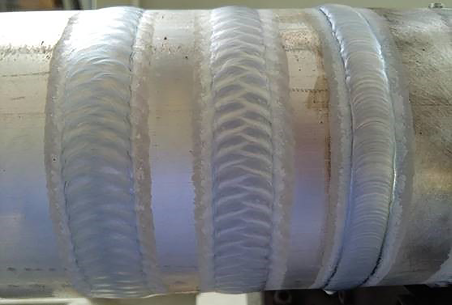
In this article, HGH3041 low hydrogen welding wire of Beijing Institute of Aeronautical Materials of Aeronautical Industry and ER50-6 welding wire of Tianjin Daqiao Welding Materials Group Co. Ltd are selected for test welding comparison. The welding results of the left two welds are achieved by using HGH3041 welding wire, and the right two welds are welded with ER50-6 filler wire. X-ray film of the middle two welds are selected for analysis. It is found that the weld formation by using HGH3041 welding wire is better. There are no defects such as undercut or hydrogen-induced crack, but there is serious undercut after ER50-6 welding wire is welded. According to the national military standard secondary welding standard, HGH3041 welding wire is selected as welding material. The comparison picture is shown in Figure 10.

Comparison of welds.
Select the middle two welds and take X-ray film, as shown in Figure 11. There are no defects in the left weld formation, and there are obvious undercut and porosity defects on the right.

X-ray image.
Based on HGH3041 welding wire, the high-strength steel workpiece with material grade of 30CrMnSiNi2A is welded in this article. The welding picture is shown in Figure 12.

Outside view of welds.
Randomly select two welds and take X-ray negatives, as shown in Figure 13. The weld inspection quality is qualified, there are no welding defects and meet the acceptance requirements of class II welds.

X-ray image.
In this article, based on the developed equipment, the expansibility research is carried out, and the aluminum alloy thick pipe commonly used in the aviation enterprise is welded. The welding pictures are shown in Figure 14, the forming effect is good, and there are no welding defects in the preliminary detection.
Outside view of welds.
Summary and prospect
Aviation products generally have high-quality requirements. At present, the company’s current circular seam welding relies heavily on the skill level of the welder and the working state during operation, and the welding quality stability is poor. The results obtained in this article are as follows: Real-time control of important parameters such as arc voltage and swing in the welding process is realized through the use of arc voltage controller and welding torch swing. Through the integration of various components of the system and the setting of welding parameters, the stability of welding parameters in the whole welding process is guaranteed, and the unfavorable factors such as welding torch jitter are reduced at the same time, so as to ensure the stability of welding seam forming, improve welding quality, and provide the production of shaft production for enterprises. The welding of aviation aluminum tubes is carried out through the developed welding system, which verifies the effectiveness of the equipment for the welding of aluminum tubes and lays the foundation for the welding of aviation aluminum materials in the future.
Footnotes
Authors’ note
LC and LH contributed equally to this work.
Declaration of conflicting interests
The author(s) declared no potential conflicts of interest with respect to the research, authorship, and/or publication of this article.
Funding
The author(s) disclosed receipt of the following financial support for the research, authorship, and/or publication of this article: This work was supported by the National Natural Science Foundation of China under grant 62163028, the Key Research and Development Plan of Jiangxi Province under grant 20202BBE53025, and Nanchang High Level Scientific and Technological Innovation Talents “Double Hundred Plan” under grant 2020131.