
Abstract
A type of manipulator configuration with four-fingers is put forward, for grasping fragile hollow workpieces, with adjustable finger length and finger pad shape. Within a certain range, the manipulator can be used to grasp the internal cross section of fragile objects with different size of circular and oval shape. The design idea and structure of the manipulator are introduced, while the join positions between the finger pad and the finger body, as determined by uniform interpolation or Chebyshev interpolation, are comparatively analyzed and researched regarding forming force contact with workpiece. During the process of grasping, the internal forces and deformations between finger pad and workpiece are analyzed, based on a constructed finite element analysis model. The calculation example shows that, under the same grasping parameters, the maximum impact force on the workpiece is reduced by 63%, when the curvature adjustment points for the finger pad are distributed according to the Chebyshev interpolation, compared to their equal spacing distribution. Research has provided a theoretical basis for the design optimization of the finger pad structure and the connection point positions. For using manipulator to grasp objects with different size of circular and oval shape, the working space of the proposed manipulator is studied. The experiments show that, the manipulator structure, as presented in this article, can meet the requirements of relevant tasks.
Keywords
Introduction
The key components of an industrial robot are its end effectors. Many specialized tools, gripper or hand 1,2 appear in the food packaging, electronic components assembly, among others. For example, the electromagnetic gripper 3 focuses on the fetching process of metal materials, while the vacuum gripper 4 is used to clip plane objects.
As a representative case of the active universal gripper, the humanoid dexterous manipulator can grasp objects of any shape. However, it is difficult to design, manufacture, and control the humanoid dexterous manipulator. The many specialized manipulators in the industrial production line have a wide range of applications. There is a great need for a universal but simple gripper that realizes a high level of adaptability as well as a gentle touch to objects with different size, shape, stiffness, and weight. 5
In the field of gripper manipulators development, research on the finger is very important. The multi-fingers grasping has always been an active research field. Studies have shown that many humans use only two fingers for grasping. In 2008, Kazuhiro Kosuge et al. developed a planar object grasping manipulator, using a fixed finger and a movable finger with two movable joints. 6 Based on the function of human fingers, Babin et al. used a three-claw wedge-shaped manipulator to complete the grasping of planar objects, placed on a rigid plane. 7 Hao et al. presented a multimode compliant gripper which can be reconfigurable to grasp a variety of shapes or adapt to specific requirements. 8
In the case of grasping fragile, deformable, and force sensitive objects, the manipulators use the inherent adaptability of elastomer materials and passive adaptation, combined with a simpler control method. For example, Amend et al. used a large number of granular materials wrapped in elastic membrane, to develop a kind of passive general gripper, able to grab and place multiple objects at the same time. 9 Shintake et al. developed a new kind of soft gripper, combining the inherent electric adhesive force and electrostatic pickup operation, suitable for handling fragile objects. 3 Saxena presented a gripper which employed contact interactions between its deforming members to delimit the output displacement such that excessive forces on the soft, fragile work-pieces are thwarted. 10 Liu et al. synthesized a compliant finger for grasping objects with size and shape variations. 11 Mouaze et al. shown a model to predict the simultaneous deformations occurring when compliant robotic fingers were grasping soft objects. 12 Kaya et al. studied a series elastic parallel gripper by simple touching in case of no visual data available. 13
As far as the industrial robots on the assembly line are concerned, picking up and discharging materials are the most basic functions. Sometimes, the manipulator gripper is also used to complete assembly task. 14,15
Concerning cylindrical objects, they are clamped from the outside with grippers that mostly use three holding jaws to form a cylindrical hole to accommodate the cylindrical shape of the parts. Regarding tubular parts, the inner bracing gripper is preferred, even though most of the inner bracing grippers only have the function of clamping and loosening the workpiece, without any auxiliary positioning and assembly capabilities.
However, the manipulator gripper used in the production line of synthetic diamond raw materials-pyrophyllite block not only needs to have the function of clamping and loosening the workpiece but also to possess the ability of assisting positioning and assembly.
Aiming at the real demand for synthetic diamond raw materials-pyrophyllite block, whose production requires the use of manipulator, a type of flexible manipulator for grabbing and assembling cylindrical-shaped hollow workpieces, based on the inner bracing grabbing method, is designed. 16 –18 The specific production line entails the handling of fragile workpieces. The designed manipulator mainly consists of three claws finger, forming a circular arc that internally grasps by bracing and a tubular palm. The structure adopts an elastic connection between the palm and the finger. During the assembly operation phase, the finger mechanism can retract and hide in the tubular palm.
On the basis of the above work, a four-finger inner bracing grab manipulator with adjustable finger length is put forward, to be used for grasping fragile hollow workpieces. Within a certain range, the manipulator can be widely used to grasp the internal cross section of circular or oval shaped objects with different radius, by adjusting the finger length and the shape of the finger pad. In this article, the structure of the manipulator is introduced, the contact precision and contact force between the finger pad and the workpiece during grasping process are analyzed. The research results are verified based on calculated simulation and actual grasping experiment.
The main innovations of this article include a manipulator with a four-finger configuration setup, which fingers can retract and hide in the palm, during the assembly operation. The manipulator configuration can successfully grasp a variety of objects with different size, circular and oval shaped workpieces, by adjusting the finger structure. A comparative analysis and calculation model of fitting accuracy were established, based on different methods used to determine the contact point between the finger pad and the surface of the object to be grasped. A finite element analysis model of the finger pad was established, to evaluate the deformation and contact force distribution, between the finger and the workpiece, during grasping.
The contents of the article are organized as follows. The functional requirements and grasping operation mode of the manipulator are introduced in the second section. The innovative configuration of the proposed grasping manipulator is discussed and a study of the fitting law of the finger pad curve is completed in the third and fourth sections, respectively. Calculation on test cases and comparison results is given in the fifth section, while in the sixth section, the contact force is simulated. In the seventh section, the notion of adjustable working space of the manipulator structure is discussed, the structural realization of the manipulator operation is studied in the eighth section. In the ninth section, prototype design and experiment are discussed, whereas the conclusions are presented in the tenth section.
The functional requirements and grasping operation mode of the manipulator
In the specific production line, the manipulator needs to complete the following operations, as shown in Figure 1: a special fragile ring (Figure 1(a)) is transferred above the terrace die (Figure 1(b)) and is assembled on the terrace die. In this article, the manipulator used for loading and transferring a workpiece is considered as an example, in order to study the operation of a special manipulator used for fragile parts.

Assembling process of the fragile ring.
Generally, there are four ways to grasp cylindrical or circular ring objects by hand, as shown in Figure 2. Namely: (a) parallel flexion grasping, (b) parallel extension grasping, (c) wraparound grasping, and (d) inner bracing grasping. It is obvious that the force application characteristics and structure action modes of the various grasping ways are different.

Four ways to grasp objects by hand.
The fourth type of grasping exhibits many defects, in real life. When the inner bracing grasping mode is adopted, it is easy for the workpiece to fall off, during high-speed motion, which is a rare occurrence, when the other three modes are adopted. The reason is that, the perception and compliance degree of the pad innerside finger is much higher than that of the nail and skin on the back of the finger, whereas the friction coefficient between the nail of the finger and the grasping object is lower. Therefore, the first three grasp methods are more frequently used in the common cases of grasping circular ring objects.
During the actual grasping action of the manipulator, the section shape of the workpiece to be captured is illustrated in Figure 3. The inner section is a regular inner circle, ellipse, rectangle, rhombus, and so on, but the outer shape is irregular, and the size difference is large. When a manipulator uses external clamping method to grasp those kinds of workpiece, three or four fingers are needed, the working space of the fingers changes significantly, whereas the positioning accuracy of the clamping is also low. This research aims to design a manipulator to complete the grasping of those kinds of workpiece.

Different sections of workpiece. (a) Inner circle, (b) inner ellipse, (c) inner rectangle, and (d) inner rhombus.
The assembly process of a fragile ring on the central terrace die of the forming mold is shown in Figure 1. When external clamping method is adopted, the manipulator needs to complete the assembly, by operating in the narrow gap between the outer wall of the central terrace die and the inner wall of the outer mold, which complicates the space collision avoidance task for the manipulator. In order to use one manipulator to complete same work, the inner bracing grip mode is a practical choice for the manipulator with four fingers. The operation modes of the manipulator are designed, according to the above operation characteristics of the assembly process, where the finger system can retract, and the palm is used to press down the fragile ring. As shown in Figure 4, based on the manipulator functional requirements, its installation lies on a horizontal and a vertical motion module (2 and 3 in Figure 4).
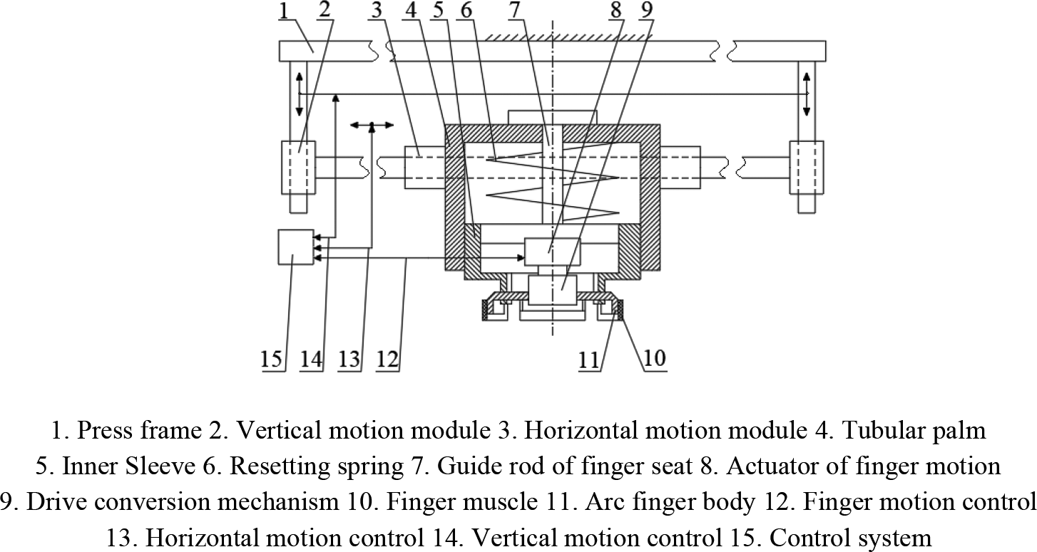
The configuration of manipulator system for producing the fragile block.
More precisely, the four fingers (11 in Figure 4), forming a circular arc or other shapes, for inner bracing type configuration, used to perform grasping and transferring tasks, are nested in the inner cylinder of a barrel-like palm (4 in Figure 4), along which they complete press assembly work in confined spaces. In order to ensure that the fingers are moving in the direction of the inner cylinder of the barrel-like palm, a guide bar structure (7 in Figure 4) is set. In order to ensure that the finger can smoothly return to its original position, after the manipulator has completed the assembly task, an elastic structure (6 in Figure 4), between the barrel-like palm and the finger body, is designed.
The operation process is decomposed, the main working process of the manipulator is shown in Figure 5. (a) The manipulator is driven to grasp and transfer the fragile ring; (b) the manipulator moves downwards and presses the fragile ring against the terrace die; (c) the fragile block is grasped and transferred.

Main working process of the manipulator. (a) Grasping and transferring the fragile ring, (b) pressing down the fragile ring, and (c) transferring pyrophyllite block.
Innovative configurations of grasping manipulator
As part of the manipulator structure, the design and selection of the finger driver are related to the working stability of the manipulator. Under normal working conditions, the constant speed cylinder can be used to drive the manipulator, 17,18 while the corresponding finger structure is designed according to the configuration illustrated in Figure 6.

Structure of the internal support manipulator.
When the manipulator is used to grasp a fragile workpiece, it is very important to study the contact state between the finger surface and the workpiece. Forming a contact surface with high fitting accuracy and reduced local pressure on the grasping contact surface is very important for the reliable execution of the grasping motion.
In previous manipulator structure designs, the finger body curvature radius is fixed, as shown in Figure 7. Rw is the inner surface radius of the workpiece and Rh is the outer surface radius of the finger body. Therefore, if the curvature radius of the workpiece changes, using the finger body of current manipulator directly contacts the workpiece, the effective surface contact cannot be formed between them.

Case where the curvature radius of the workpiece is different from that of the finger body.
In order to improve the contact state between the finger and the workpiece, a finger body with adjustable curvature radius is developed. A finger structure, designed to operate with different working radius, improves the fitting precision of the contact surface, by adapting to the radius change of the workpiece grasped. The structure is shown in Figure 8.
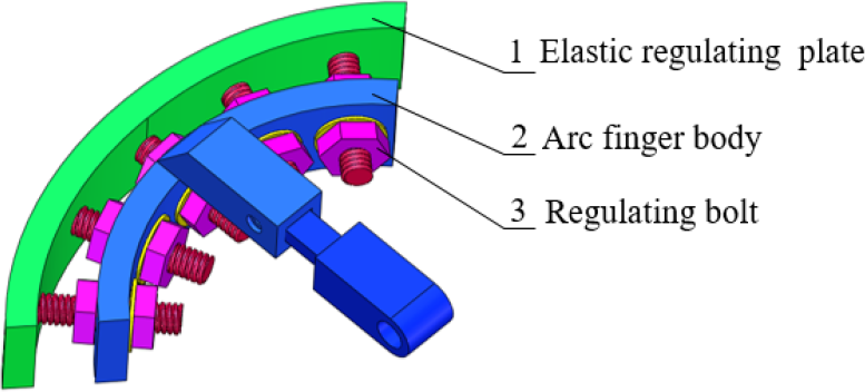
Single finger structure with adjustable curvature radius.
The designed finger body uses plunging joint, composed of a fixed part and an adjusting part. Within a certain range, the overall length of the finger body is adjusted to adapt, at any time, to the diameter of the workpiece.
Specifically, an elastic regulating plate is designed, along with are tractable adjusting mechanism, arranged between the finger body and the elastic regulating plate. The curvature radius of the elastic regulating plate is adjusted, to match the internal surface curvature of the workpiece, by changing the actual length of the adjusting screw in the retraction mechanism. There is a rubber layer attached on the outer surface of the elastic adjusting plate, acting as the finger pad. As the elastic regulating plate grasps the workpiece, the grasping contact area, between the finger pad and the inner wall of the workpiece, is maximized, ensuring the operation stability and reducing the pressure on the workpiece, to avoid any damage.
When this kind of manipulator grasps a workpiece with circular and elliptic sections, the respective working states are shown in Figure 9. (This kind of manipulator also can grasp the inner rectangle or the inner rhombus workpieces, the specific technology isn’t discussed here.)

The finger arrangement of the manipulator grasping the workpiece with circular and elliptic sections. (a) Circular workpiece and (b) oval workpiece.
Fitting law of the finger pad curve (surface)
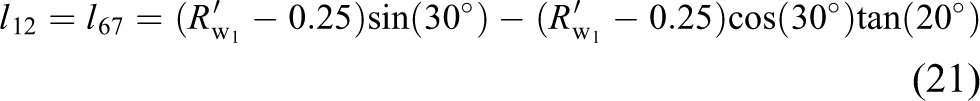
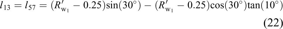
As shown in Figure 8, adapting to the diameter and contour change of a thin-walled workpiece is achieved by adjusting the outer contour of the finger pad through a regulating bolt stroke. The connection points between the adjusting bolt and the elastic adjusting plate are called fitting points between the plate and the workpiece surface to be grasped (referred to as the fitting node). In order to improve the internal support force and contact friction for the workpiece, the fitting errors between the elastic adjusting plate and the workpiece surface are calculated.
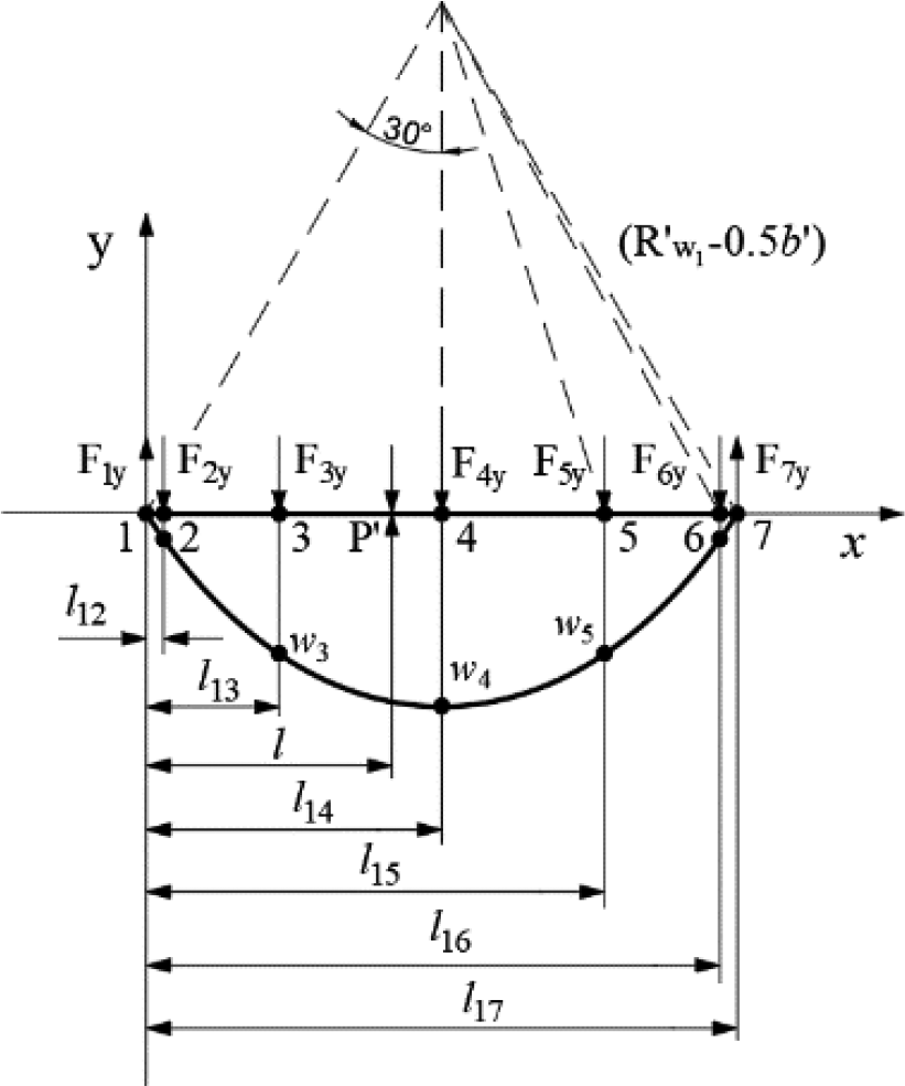
For a single finger, the calculation model is shown in Figure 10.
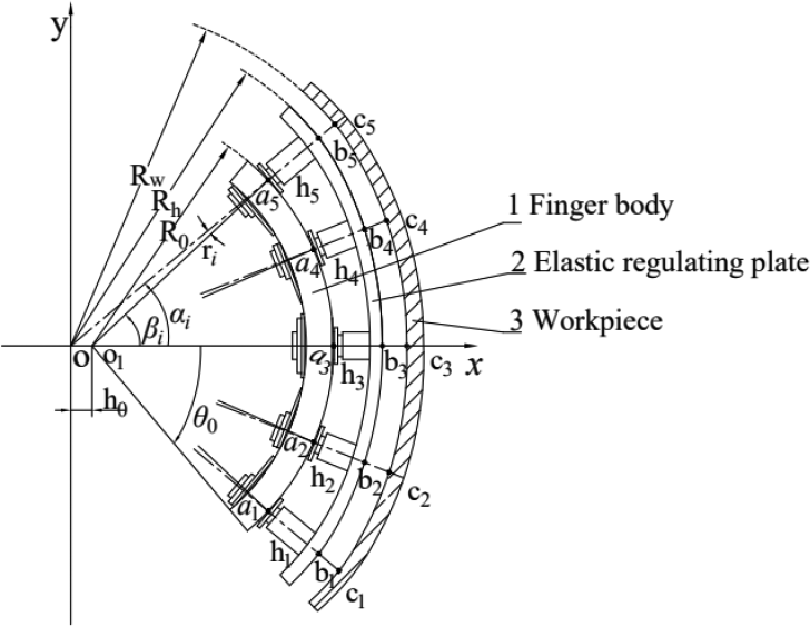
Calculation model of the finger working for fitting workpiece surface.
Parameter settings
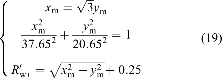
As shown in Figure 10, the center of the circular workpiece is denoted as point O, while the coordinates system xOy is set. ① The position of the intersecting points between the center line of the studs on the finger body and the outer surface of the finger body is denoted as a
1, a
2, a
3, a
4, a
5. The arc center of the finger body is set as point O
1. The parameters of vector
The calculation of fitting nodes
According to the limiting conditions of the structure, five points (c
1, c
2, c
3, c
4, and c
5) can be selected, within the angle range
According to the structural parameters and calculation model in Figure 10, for any point


In order to realize the accurate fitting of the finger working surface to the grasped workpiece surface, let

and
where, h
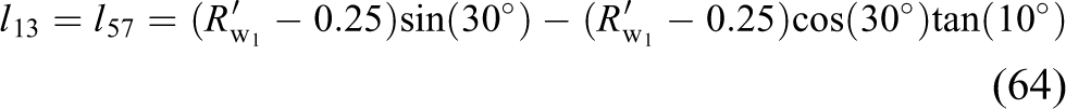
0 can be determined by adjusting the length of the knuckles, while Rw
, R
0, and
(1) Equipartition arrangement of fitting points
The fitting points are arranged following the equiangular interval within the range

Furthermore, the position of each node can be calculated.
(2)Chebyshev interpolation arrangement of fitting points
The fitted curve is expressed by the Chebyshev polynomial 19 as shown in equation (5)

Let

Based on

Following

These two groups of points are called the Chebyshev points and they play an important role in interpolation. According to Figure 11, the Chebyshev points happen to be the abscissa of equidistant points on the unit circle, which are dense near the endpoints of the interval.
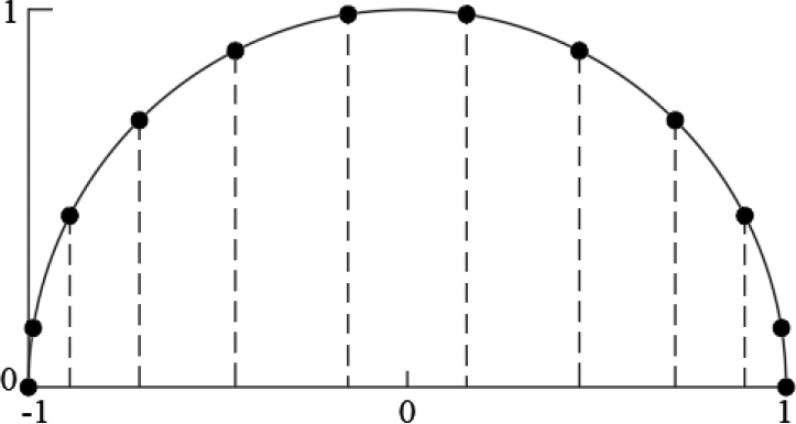
The Chebyshev interpolation points.
The Chebyshev points can be used as interpolation nodes, to minimize the maximum error of the function fitted on the interpolation interval.
Considering the interpolation points are set as

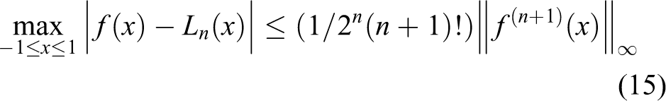
The maximum value of the interpolation remainder can be expressed as

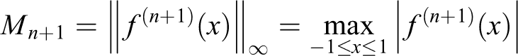
where the function
If the interpolating nodes are the null points of the function

If


where
According to the range theory

Based on equation (14), there can be a conclusion about the interpolation error being minimized.
Considering that, the interpolation nodes
Regarding the interpolation within a generic interval

According to Chebyshev interpolation theory, the position of interpolation nodes can be determined as follows

Interpolation angle range
Angle distribution of interpolation points

Calculation examples and comparison
Research on contact fitting between the outer surface of the finger and the inner surface of the workpiece is about analyzing the performance of the fitted curve. Here variation range of the
For the equipartition interpolations, the positions of the fitting points can be expressed as

For the Chebyshev interpolations, the positions of the fitting points can be expressed as

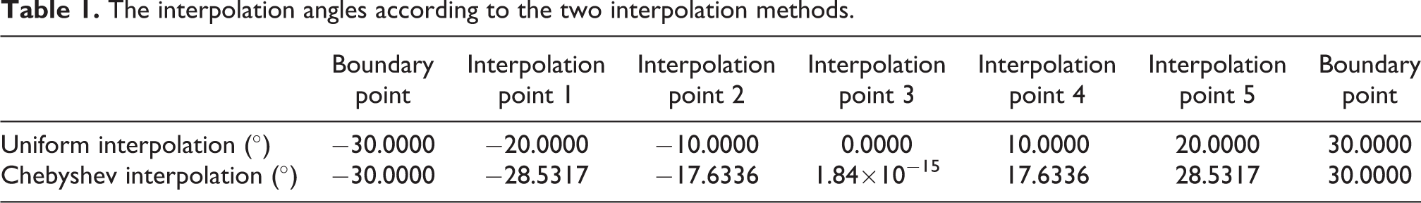
Interpolation angles are determined by using two interpolation methods, as listed in Table 1.
The interpolation angles according to the two interpolation methods.
When adjusting bolts are arranged with the calculated data in Table 1, the deformation model of the elastic adjustment plate is shown in Figure 12.

The deformation model of elastic regulating plate. (a) The uniform interpolation model and (b) the Chebyshev interpolation model.
Hyperstatic problem and deflection curve equation of the elastic regulating plate
Following, the case of the manipulator grasping a workpiece with a specific inner elliptic section is illustrated.
The curve equation of the inner surface for the elliptic workpiece is set to be

Curve fitting principle.
See Figures 12 and 13, boundary point 1 and boundary point 7 are the contact points between the edge line of the end face of the elastic regulating plate and the inner surface of the workpiece, respectively. The length of the elastic adjusting plate before deformation can be obtained by calculating the distance between the two boundary points.
Considering that the coordinates of the boundary point 7 on the long axis of the target curve to be fitted are
The distance between the boundary point 7 on the long axis and the origin of the coordinates axis is obtained as:
Similarly, the distance between the boundary point on the short axis and the origin of the coordinates axis is obtained as follows:
The length of the elastic adjustment plate can be obtained as follows

Substituting the respective data, the calculation produces the long axis adjustment plate length as:
The deflection curve equation and the interpolation angle are sketched in SolidWorks, according to a 1:1 ratio of the model representation, as shown in Figure 13.
The deformation displacements wi of the corresponding interpolation points, on the real and virtual axes, can be measured, as shown in Tables 2 and 3.
The deformation of interpolation points on the real axis for two interpolation method (unit: mm).

The deformation of interpolation points on the virtual axis for two interpolation method (unit: mm).

The data in Tables 2 and 3 show that the force and the corresponding deformation of the elastic regulating plate are symmetric.
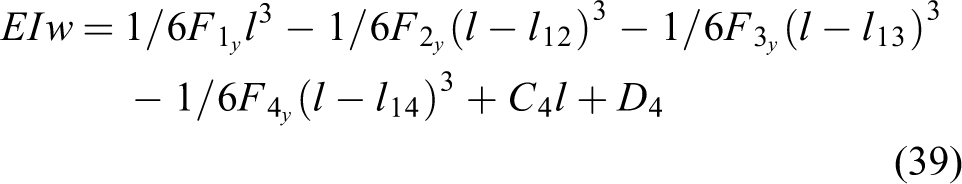
Based on the solution approach for the deflection curve of the beam, the deflection curve of the elastic regulating plate is calculated.
Uniform interpolation
The coordinates system of the uniform interpolation model (real axis) is shown as Figure 14.

The coordinates system of the uniform interpolation model (real axis).
Along the real axis direction, the distance between each interpolation point and boundary point 1 can be expressed as follows


By substituting relevant parameters, the following result is derived

The force balance equation of the elastic regulating plate is established as follows

When

Then, the differential equation of the deflection curve can be expressed as follows

where E and I are the elastic modulus and the moment of inertia of the elastic regulating plate, respectively.
By integrating equation (28), the rotation angle equation and the deflection curve equation can be obtained as


where C 1, D 1 are the integral constants. Hereinafter, Ci , Di have the same meaning.
Similarly, when


When


When


When


When


According to the boundary conditions, when l = 0, w = 0; when l = l 17, w = 0.
After substituting the data into equations (26) and (41), respectively, the following relations are derived

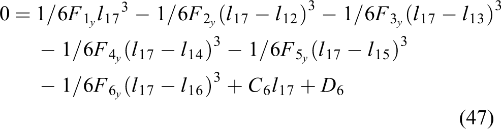
According to the curve smoothness conditions, the corresponding equations of the interpolation nodes can be established as follows


According to the geometric deformation conditions, after substituting the corresponding deformation of interpolation points 2, 3, and 4 into the corresponding equations of the deflection curve, the following equations can be obtained:
When

When

When

where E = 1.97 × 10⁵ MPa is the elastic modulus of the elastic regulating plate; the material is 65 Mn;
The force balance equation of the elastic regulating plate is established as follows

The relevant parameters are entered into the equations (21) to (56) and the calculation results can be obtained as follows
The above calculated data are substituted into the respective equations. The equation of deflection curve of the elastic regulating plate can be obtained as follows
When

When

When

When

When

When

Chebyshev interpolation
The coordinates system of the uniform interpolation model (real axis) is shown as Figure 15.
The coordinates system of the Chebyshev interpolation model (real axis).
Regarding the real axis direction, the distance between each interpolation point and boundary point 1 can be expressed as follows:


By substituting the relevant parameters, the following results are produced:

The force balance equation of the elastic regulating plate is established as follows

The calculation process for the deflection curve is similar to that of the uniform interpolation, so the specific process is omitted.
Substituting the relevant parameters into the respective equations (63) to (68), the calculation results can be obtained as follows

The above calculated data are substituted into the respective equations. The deflection curve equation of the elastic regulating plate can be obtained as follows:
When

When

When

When

When
When

The calculation method of the equation of the flexure curve of the elastic adjustment plate, at the short axis, is similar to that of the long axis, so it is not included in the description.
Comparison of two interpolation methods regarding fitting precision
Under the assumption of constant thickness, as the elastic regulating plate deforms, the models shown in Figure 16 are derived, after two groups deflection curve equations (57) to (62), (69) to (74) are imported into SolidWorks, respectively.
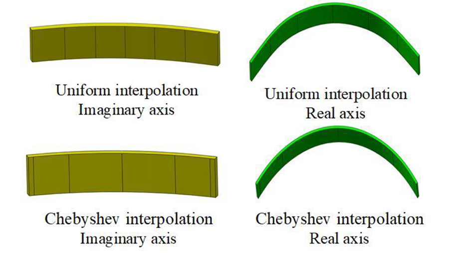
Four adjustable plate models.
The fitting deflection curve error, using the uniform interpolation and the Chebyshev interpolation, can be calculated.
Set a point
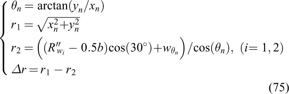
where, when the fitting error of the elastic regulating plate along the long axis direction or along the short axis direction is calculated respectively, i is 1 or i is 2 correspondingly. According to a point position

The fitting error of the two interpolation methods. (a) Real axis and (b) imaginary axis.
Combined with equation (75), it can be seen from the fitting error curve Figure 17 that the deformation fitting errors
See the fitting error curve Figure 17, the deformation fitting errors
Contact force simulation
The output of the linear motion driver is converted into translational motion of the finger body, through the corresponding mechanism. The actions of opening and closing are performed by the finger body, enabling the manipulator to finally achieve the inner brace grasping operation.
In the simulation process, the influence of the soft rubber, covering the outer surface of the elastic regulating plate, on the contact surface is ignored. The elastic regulating plate, as well as the oval inner wall workpiece being assembled in pairs, at an interval of 90°, are shown in Figure 18.

The assembly of the two elastic regulating plates. (a) The assembly of uniform interpolation and (b) the assembly of Chebyshev interpolation.
The entity modeling in Figure 18 is imported into ANSYS Workbench, in order to carry out simulation analysis. The contact points in the assembly will be automatically captured by the ANSYS system and contact pairs will be established. Generally, two objects in contact will not penetrate each other, so an appropriate contact relationship should be coded in the software, to prevent the penetration between the two contact models in the calculation process.
The material of the elastic regulating plate is 65Mn, the material of the workpiece is typical fragile quartz glass 20 and the inner support force is set as 15 N. The contact type of the two models is set as frictional contact with a friction coefficient set to 0.5. 21
After the finite element analysis is executed, the normal stress distribution nephogram of the workpiece is obtained, shown as Figure 19.

Stress distribution nephogram of the workpiece. (a) Stress distribution nephogram of the contact model using the uniform interpolation. (b) Stress distribution nephograms of the contact model using Chebyshev interpolation.
As shown in Figure 19, based on the equivalent interpolation simulation model, the maximum normal stress, along the gripping direction, on the elliptical glass ring, is 149.63 MPa, whereas in the Chebyshev interpolation simulation model, the respective value is 88.259 MPa. That is, under the same grasping parameters, the maximum impact force on the workpiece is reduced by 63%, when the curvature adjustment points for the finger pad are distributed according to the Chebyshev interpolation, compared to their equal spacing distribution. This law is very useful for the manipulator to grasp the thin wall fragile workpiece.
According to a comprehensive analysis of the fitting error graph and the contact stress cloud, a better gripping effect would be obtained by using the Chebyshev interpolation method to arrange the adjusting bolts.
Adjustable working space of manipulator structure
The manipulator configuration can successfully grasp a variety of objects with different size, circular and oval shaped workpieces, by adjusting the finger structure. In order to explore the workspace of a manipulator with an adjustable four-fingers curvature, the simplified model of the manipulator finger structure is shown in Figure 20. The working space of the manipulator’s long-axis is mainly related to the size of

Simplified model of the manipulator fingers.
The working space of a four-fingers manipulator can be represented by the part of the finger structure enclosing the inner surface of the workpiece (Figure 21).

Inner contour curve range of graspable workpiece.
The linear actuator of the four-claw manipulator adopts the MHS4-25D parallel open/close type air gripper by SMC company,
22–23
which performs equal open/close strokes at the four outputs, thus
Regarding the task of grasping the oval inner wall parts, the long and short axis change the operational range of the manipulator to:
Referring to Figure 20, the adjustable range of each point can be derived from the range variation of
The inner surface contour curve equation of the elliptical workpiece is set as

Manipulator’s workspace.
The structural realization of the manipulator operation
The manipulator operation process must ensure the stability and reliability of the workpiece grasping task. Considering the workpiece being fragile and consisting of thin-walled parts, the contact forces between the fingers and the workpiece need suitable control in order to avoid destroying the workpiece while grasping it. For this purpose, the linear motion driver uses pressure cylinder to control the grasping finger’s operation process.
In this kind of manipulator, a kind of MHS4 parallel open and close circular main cylinder made by SMC, is used for the actuation of the fingers. 22,23 These cylinders can be actuated by constant pressure. Relevant operations can be performed by installing the respective arc fingers on the output slider of the selected translational cylinder. The cylinder is controlled and driven by a wedge cam and exhibits a repetition accuracy of 0.01 mm.
As shown in Figure 23, in the translational cylinder, the piston is fixed to the wedge cam. After air intake, the cylinder drives the piston, which in turn drives the wedge came to move, driving the output slider to move horizontally. The finger body is fixed to the output slider, so the cam motion finally drives the finger to translate linearly and complete the grasp or release of the workpiece.
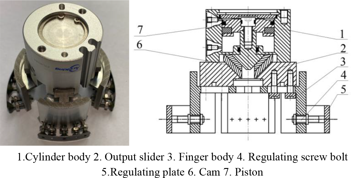
Schematics of the grasping finger.
Based on the translational cylinder gripper selected and the manipulator structure shown in Figure 6, the proposed design provides for a finger’s configuration suitable for inner brace grasping, as shown in Figure 24.

The structure of the internal support grasping manipulator.
Prototype design and experiment
According to the above principles, the experimental prototype is designed and produced, as shown in Figure 25. In the experimental prototype, the vertical and horizontal motion modules use KE09010C-250AF0M and KE09010C-500AF0M from HIWIN Company, the stepper motors use 60CM30X, the motor control system adopts TRIO motion control card MC403, and the control system program is written using Trio BASIC.

The experimental prototype.
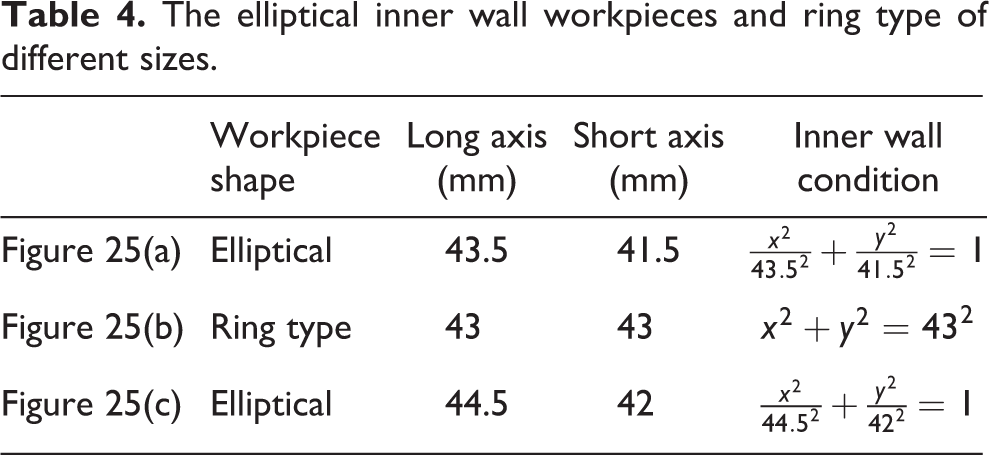
For the workpieces grasped, from left to right, the elliptical inner wall workpieces and ring type workpiece with different sizes are shown in Figure 26, specifically, which are listed in Table 4.

Workpieces with different sizes and shapes.
The elliptical inner wall workpieces and ring type of different sizes.
In Figure 27, the manipulator grasps the elliptical inner wall workpiece with the larger size (i.e. workpiece shown as Figure 26(c)) to perform an assembly with a corresponding mating part. The workflow in Figure 27 is as follows: (a) The manipulator is driven to complete the positioning above the workpiece to be grasped; (b) The manipulator is driven to move downwards and reach an appropriate position, where the finger is driven to grasp the workpiece; (c) The workpiece is transferred to a position above the mating part; (d) The manipulator moves downwards and presses the workpiece against the mating part.

The manipulator grasps and assembles the workpiece (https://www.bilibili.com/video/BV1Td4y1k79v/).
Accordingly, the timeline postures of the manipulator grasping and transferring the other two internal contour workpieces are shown in Figure 28, where the manipulator grasps the elliptic workpiece (shown in Figure 26(a)) (https://www.bilibili.com/video/BV1V14y157Jd/) and the circular workpiece (shown in Figure 25(b)) (https://www.bilibili.com/video/BV1ZP411F7gx/), as illustrated in the subfigures, respectively.

Manipulator transfers workpieces with different size and shape.
The experimental results show that, the manipulator system can successfully grasp the fragile thin walled elliptic and cylindrical inner wall workpieces of different size, by means of adjusting the radius of the elastic regulating plate. According to the observation, in the grasping and transferring process, the manipulator system runs smoothly, the workpiece grasped does not fall off, deform and damage.
Conclusions
An internal bracing grasping structure is developed in the designed manipulator, exhibiting adjustable finger length and an adjustment system for the curvature of the finger elastic regulating plate. The manipulator can grasp the thin walls are fragile elliptic and cylindrical inner wall workpieces with different size and shapes, which can realize high precision contact between finger and workpiece surface.
The research results show that, in the case of grasping fragile thin-walled workpieces, employing a finger elastic regulating plate is more suitable, resulting in a reduced maximum impact force on the workpiece, when the Chebyshev interpolation is used to confirm the curvature adjustment points on the plate.
Through theoretical analysis and experimental verification, the manipulator can meet the work requirements. Of course, in the actual production, we can also manufacture one corresponding fixed size finger for each workpiece size. However, as the processing cost of each set of fixed size fingers is about 2200USD, undoubtedly, processing more varieties of such fingers will increase the production cost of the enterprises.
This article mainly studies the static pressure between the finger and the workpiece during the grasping process. In the follow-up study, we will study the impact force at the moment of grabbing and further optimize the fitting law of the elastic regulation plate.
The presented research idea provides a reference for designing manipulators with special performance requirements.
Supplemental material
Supplemental Material, sj-pdf-1-arx-10.1177_17298806231157339 - Configuration design and grasping contact accuracy analysis of a four-finger manipulator used for grasping fragile objects of elliptic cross section
Supplemental Material, sj-pdf-1-arx-10.1177_17298806231157339 for Configuration design and grasping contact accuracy analysis of a four-finger manipulator used for grasping fragile objects of elliptic cross section by Dongxia Wang, Liangwen Wang, Hongchang Xie, Zhenzhen Wu, Guizhong Xie, Caidong Wang, Huadong Zheng and Zhuang Wang in International Journal of Advanced Robotic Systems
Footnotes
Declaration of conflicting interests
The author(s) declared no potential conflicts of interest with respect to the research, authorship, and/or publication of this article.
Funding
The author(s) received financial support for the research, authorship, and/or publication of this article: This project was supported by the National Natural Science Foundation of China (Grant No.52075500, 52005453), the Program for Science & Technology Innovation Talents in Universities of Henan Province(Grant No. 22HASTIT023), and the Key Scientific Project of Henan Province (Grant No. 232102221033, 222102220091), Zhengzhou Key Laboratory of Intelligent Assembly Manufacturing and Logistics Optimization, and Henan Engineering Technology Research Center of Intelligent Cold Chain Logistics Equipment Manufacturing, China.
Supplemental material
Supplemental material for this article is available online.
References
Supplementary Material
Please find the following supplemental material available below.
For Open Access articles published under a Creative Commons License, all supplemental material carries the same license as the article it is associated with.
For non-Open Access articles published, all supplemental material carries a non-exclusive license, and permission requests for re-use of supplemental material or any part of supplemental material shall be sent directly to the copyright owner as specified in the copyright notice associated with the article.